EP0791472B1 - Tintenstrahlaufzeichnung - Google Patents
Tintenstrahlaufzeichnung Download PDFInfo
- Publication number
- EP0791472B1 EP0791472B1 EP97301062A EP97301062A EP0791472B1 EP 0791472 B1 EP0791472 B1 EP 0791472B1 EP 97301062 A EP97301062 A EP 97301062A EP 97301062 A EP97301062 A EP 97301062A EP 0791472 B1 EP0791472 B1 EP 0791472B1
- Authority
- EP
- European Patent Office
- Prior art keywords
- nozzle column
- media
- nozzle
- rotational misalignment
- Prior art date
- Legal status (The legal status is an assumption and is not a legal conclusion. Google has not performed a legal analysis and makes no representation as to the accuracy of the status listed.)
- Expired - Lifetime
Links
Images


Classifications
-
- B—PERFORMING OPERATIONS; TRANSPORTING
- B41—PRINTING; LINING MACHINES; TYPEWRITERS; STAMPS
- B41J—TYPEWRITERS; SELECTIVE PRINTING MECHANISMS, i.e. MECHANISMS PRINTING OTHERWISE THAN FROM A FORME; CORRECTION OF TYPOGRAPHICAL ERRORS
- B41J11/00—Devices or arrangements of selective printing mechanisms, e.g. ink-jet printers or thermal printers, for supporting or handling copy material in sheet or web form
- B41J11/36—Blanking or long feeds; Feeding to a particular line, e.g. by rotation of platen or feed roller
- B41J11/42—Controlling printing material conveyance for accurate alignment of the printing material with the printhead; Print registering
-
- B—PERFORMING OPERATIONS; TRANSPORTING
- B41—PRINTING; LINING MACHINES; TYPEWRITERS; STAMPS
- B41J—TYPEWRITERS; SELECTIVE PRINTING MECHANISMS, i.e. MECHANISMS PRINTING OTHERWISE THAN FROM A FORME; CORRECTION OF TYPOGRAPHICAL ERRORS
- B41J25/00—Actions or mechanisms not otherwise provided for
- B41J25/001—Mechanisms for bodily moving print heads or carriages parallel to the paper surface
-
- B—PERFORMING OPERATIONS; TRANSPORTING
- B41—PRINTING; LINING MACHINES; TYPEWRITERS; STAMPS
- B41J—TYPEWRITERS; SELECTIVE PRINTING MECHANISMS, i.e. MECHANISMS PRINTING OTHERWISE THAN FROM A FORME; CORRECTION OF TYPOGRAPHICAL ERRORS
- B41J2/00—Typewriters or selective printing mechanisms characterised by the printing or marking process for which they are designed
- B41J2/005—Typewriters or selective printing mechanisms characterised by the printing or marking process for which they are designed characterised by bringing liquid or particles selectively into contact with a printing material
- B41J2/01—Ink jet
- B41J2/17—Ink jet characterised by ink handling
- B41J2/175—Ink supply systems ; Circuit parts therefor
- B41J2/17503—Ink cartridges
Definitions
- the present invention relates to ink jet printing devices, and more particularly to techniques for improving print quality, e.g. compensating for microbanding.
- An ink jet printer forms a printed image by printing a pattern of individual dots at particular locations of an array defined for the printing medium.
- the locations are conveniently visualized as being small dots in a rectilinear array.
- the locations are sometimes called “dot locations,” “dot positions,” or “pixels”.
- the printing operation can be viewed as the filling of a pattern of dot locations with dots of ink.
- Ink jet printers print dots by ejecting very small drops of ink onto the print medium, and typically include a movable carriage that supports one or more printheads each having ink ejecting nozzles.
- the carriage traverses over the surface of the print medium, and the nozzles are controlled to eject drops of ink at appropriate times pursuant to command of a microcomputer or other controller, wherein the timing of the application of the ink drops is intended to correspond to the pattern of pixels of the image being printed.
- An ink jet printhead includes an array of nozzles through which droplets of ink are fired.
- the nozzles are commonly arranged in side by side columns that are aligned with the media axis, and the nozzles of one column are staggered along the media axis relative to the nozzles of the other columns in accordance with the print or dot resolution of the printhead.
- the distance along the media axis between diagonally adjacent nozzles which is also called the nozzle pitch, is equal to the resolution dot pitch of the desired dot resolution (e.g., 1/600 inch for 600 dpi).
- the physical spacing between the columns of nozzles in a printhead is compensated by appropriate data shifts in the swath print data so that the two columns function as a single column of nozzles.
- a consideration with implementing a multiple column nozzle array is the need for precise mechanical alignment of the columns with the media axis. If the columns of a nozzle array are positioned so as to be tilted or rotated relative to the media axis about an axis that is orthogonal to a plane that is parallel to the media axis and the carriage scan axis, the spacing between adjacent nozzles along the media axis will not be equal. In particular, the spacing between one nozzle an adjacent nozzle in one direction along the media axis will be less than the dot resolution while the spacing between such nozzle and an adjacent nozzle in the other direction along the media axis will be greater than the dot resolution. The result is a printed output wherein the dots are misaligned along the carriage axis and along the media axis.
- the misalignment' along the carriage axis can be corrected by controlling the timing of the print pulses provided to the nozzles of a printhead.
- JP 57102364A discloses an arrangement for adjusting the head mounting error in an ink jet printer which has left and right nozzle columns, the nozzles in the respective column being regularly staggered.
- the disclosure of this document corresponds generally to the preamble of claims 1 and 7.
- JP 5262824A discloses a mechanism for adjusting the inclination of a printhead, in which a suitable spacer is attached to the printhead.
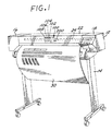
- FIG. 1 is a perspective view of an ink jet large format printer/plotter incorporating the teachings of the present invention.
- FIG. 2 is a perspective view of the carriage assembly, carriage positioning mechanism, and print media positioning mechanism of the printer/plotter of FIG. 1.
- FIG. 3 is a simplified perspective view of a media positioning system of the print/plotter of FIG. 1.
- FIG. 4 is a simplified block diagram cf a printer controller for controlling the swath printer of FIG. 1.
- FIG. 5 is a schematic plan view illustrating a nozzle array of the printhead cartridge of the printer of FIG. 1.
- FIG. 6 schematically depicts a nozzle array that is rotationally misaligned in the counterclockwise direction relative to the media advance axis.
- FIG. 7 schematically depicts a nozzle array that is rotationally misaligned in the clockwise direction relative to the media advance axis.
- FIG. 8A schematically sets forth a dot pattern that would be printed at a fixed position along the carriage axis by the nozzles of the counterclockwise misaligned nozzle array of FIG. 6.
- FIG. 8B schematically sets forth a dot pattern that would be printed in accordance with the invention at a fixed position along the carriage axis by the nozzles of the counterclockwise misaligned nozzle array of FIG. 6.
- FIG. 8C schematically sets forth another dot pattern that would be printed in accordance with the invention at a fixed position along the carriage axis by the nozzles of the counterclockwise misaligned nozzle array of FIG. 6.
- FIG. 9A schematically sets forth a dot pattern that would be printed at a fixed position along the carriage axis by the nozzles of the clockwise misaligned nozzle array of FIG. 7.
- FIG. 9B schematically sets forth a dot pattern that would be printed in accordance with the invention at a fixed position along the carriage axis by the nozzles of the clockwise misaligned nozzle array as shown in FIG. 7.
- FIG. 9C schematically sets forth another dot pattern than would be printed in accordance with the invention at a fixed position along the carriage axis by the nozzles of the clockwise misaligned nozzle array of FIG. 7.
- FIG. 10 sets forth a flow diagram of a printing procedure in accordance with the invention that compensates for media axis alignment error caused by rotational misalignment of a nozzle array.
- FIG. 11 sets forth a flow diagram of another printing procedure in accordance with the invention that compensates for media axis alignment error caused by rotational misalignment of a nozzle array.
- FIG. 12 sets forth a flow diagram of a further printing procedure in accordance with the invention that compensates for media axis alignment error caused by rotational misalignment of a nozzle array.
- FIG. 13 sets forth a flow diagram of a procedure in accordance with the invention that compensates for media axis alignment error caused by rotational misalignment of a plurality of nozzle arrays.
- FIG. 1 is a perspective view of a thermal ink jet large format printer/plotter incorporating the teachings of the disclosed invention.
- the printer 10 includes a housing 12 mounted on a stand 14. The housing has left and right drive mechanism enclosures 16 and 18. A control panel 20 is mounted on the right enclosure 18.
- a carriage assembly 100 illustrated in phantom under a transparent cover 22, is adapted for reciprocal motion along a guide rail 24, also shown in phantom. The position of the carriage assembly 100 in a horizontal or carriage scan axis is determined by a carriage positioning mechanism 110 (FIG. 2) with respect to an encoder strip 120 (FIG. 2) as discussed more fully below with respect to FIG. 2.
- a print medium 30 such as paper is positioned along a vertical or media advance axis by a media axis drive mechanism that includes a print roller 154 (FIGS. 2 and 3).
- FIG. 2 is a perspective view of the carriage assembly 100, the carriage positioning mechanism 110 and the encoder strip 120.
- the carriage positioning mechanism 110 includes a carriage position motor 112 which has a shaft 114 extending therefrom through which the motor drives a small belt 116. Through the small belt 116, the carriage position motor 112 drives an idler 122 via the shaft 118 thereof. In turn, the idler 122 drives a belt 124 which is secured by a second idler 126.
- the belt 124 is attached to carriage assembly 100 and adapted to slide therethrough.
- the position of the carriage assembly 100 in the carriage axis is determined precisely by the use of the encoder strip 120.
- the encoder strip 120 is secured by a first stanchion 128 on one end and a second stanchion 129 on the other end.
- the encoder strip 120 may be implemented in a manner disclosed and claimed in commonly assigned U.S. Patent No. 5,276,970.
- a carriage position encoder (not shown) having an optical reader is disposed on the carriage assembly and provides carriage position signals.
- the carriage assembly 100 removably supports four ink jet printhead cartridges or pens 102, 104, 106, and 108 that store ink of different colors (e.g., black, yellow, magenta and cyan ink, respectively). As the carriage assembly 100 translates along the carriage scan axis, selected ink firing resistors of the printheads of the printhead cartridges 102, 104, 106 and 108 are activated such that ink drops are fired through associated ink jet nozzles.
- ink of different colors e.g., black, yellow, magenta and cyan ink, respectively.
- FIG. 3 is a perspective view of a simplified representation of a media positioning system 150 utilized in the printer of FIG. 1.
- the media positioning system 150 includes a media axis motor 152 that drives the print roller 154.
- the position of the print roller 154 is determined by a media position encoder 156.
- the media position encoder 156 includes a disc having a plurality of apertures 159 therein.
- an optical reader 160 provides a plurality of output pulses which facilitate the determination of the position of the print roller 154 and, therefore, the position of the print medium 30 as well.
- Position encoders are well known in the art. See for example, Economical High-Performance Optical Encoders by Howard C. Epstein et al., published in the Hewlett-Packard Journal, October 1988, pages 99-106.
- an optical sensor module 200 is mounted on the carriage assembly 100.
- the sensor module optically senses test lines printed by a printhead to determine rotational misalignment of the printhead relative to the media advance axis as measured in a plane that contains the media advance axis and is parallel to the carriage axis.
- the angle of such rotational misalignment is referred to herein as the angle ⁇ Z .
- the sensor module 200 is implemented with a phase plate, and suitable processing circuitry is provided for processing the output thereof, as disclosed in commonly assigned U.S. Patent 5,404,020.
- the control system includes an interface 51 which receives print data from a host computer, for example, and stores the print data in a buffer memory 53.
- a microprocessor controller 55 is configured to process the print data to produce raster data that is stored in a bit-map memory 57a contained in a random access memory (RAM) 57 provided for the use of the microprocessor controller 55.
- a read-only memory 59 is also provided as appropriate for the use of the microprocessor controller 55. Processes in accordance with the invention, as described further herein, can be performed by the microprocessor controller 55 in conjunction with processes contained in the read-only memory 59.
- a print controller 61 transfers portions of the raster data from the bit-map memory 57a to a swath memory 63 and provides swath data to a printhead driver controller 43 which controls printhead drivers 67 that drive the ink firing elements of the printhead cartridges 102, 104, 106, 108.
- the print controller 61 further controls the media axis drive motor 152 which moves the print roller 154 pursuant to media motion commands from the print controller 61.
- the media position encoder 156 provides information for the feedback control of the media axis drive motor 152.
- a carriage axis encoder 73 provides feedback information for the feedback control of the carriage scan axis drive motor 112 which positions the ink jet cartridge supporting carriage assembly 100 pursuant to carriage motion commands from the print controller 61.
- a multichannel analog-to-digital (A/D) converter 75 receives analog signals based on the outputs of the optical sensor 200 and provides digital versions of such analog signals for processing to determine the rotational misalignment of a nozzle array.
- FIG. 5 illustrated therein is a schematic representation of a nozzle array 91 that is included in each of the printhead cartridges 102, 104, 106, 108, as viewed from above the nozzle array (i.e., the print media would be below the plane of the figure).
- the nozzle array 91 includes a plurality of nozzles arranged in a left column 91L and a right column 91R which are parallel to a nozzle array longitudinal axis L, wherein the nozzles of one column are staggered along the nozzle array longitudinal axis L.
- the nozzle pitch is known as the nozzle pitch, and by way of example is equal to the dot pitch of the desired dot resolution (e.g., 1/600 inch for 600 dpi).
- the left and right columns 91L, 91R are separated by a column separation distance D, and in use the physical spacing between the columns is compensated by appropriate data shifts in the swath print data so that two columns function as a single column of nozzles.
- the left and right nozzle columns 91L, 91R are parallel to a media advance axis A, as shown in FIG. 5, whereby the nozzle array longitudinal axis L is parallel to the media advance axis A.
- the nozzle columns 91L, 91R may not be parallel to the media axis, for example as a result of mechanical tolerances between the printhead cartridge and the print carriage, and thus would be only generally aligned with the media axis.
- the nozzles of the nozzle columns are identified in sequence along the longitudinal axis L starting with the nozzle that would be first encountered by the print medium when advanced along the media axis direction, which is indicated by the arrowhead on the media advance axis A, when the nozzle columns are aligned with the media advance axis.
- the nozzle that would be furthest along the media advance'direction is the nozzle of the left column that is uppermost in the figure
- such nozzle is nozzle 1 and the nozzles of the left nozzle column are identified by odd numbers.
- the nozzles of the right nozzle column are identified by even numbers starting with the nozzle of the right column that is uppermost in the figure.
- FIG. 6 schematically depicts a nozzle array that is rotationally misaligned in the counterclockwise direction relative to the media advance axis A
- FIG. 7 schematically depicts a nozzle array that is rotationally misaligned in the clockwise direction relative to the media advance axis A.
- the amount of rotational misalignment ⁇ Z is relatively small, and thus the amount of error or misalignment along the media axis in the spacing between the left column nozzles and the right column nozzles is very closely approximated by (D*tan ⁇ Z ), wherein D is the distance between the left and right nozzle columns. This can be readily understood by visualizing the nozzle columns as being rotated about an axis that passes through a top or bottom nozzle of one of the nozzle columns.
- the other nozzle column is therefore displaced by an amount that is equal to (D'*tan ⁇ Z ), wherein D' is the projection on the carriage axis of the distance between nozzle columns. Since ⁇ Z is relatively small, utilizing D instead of D' is reasonably accurate.
- the rotational misalignment ⁇ Z is always a positive angle regardless of the direction of the rotational misalignment. In this manner, the misalignment (D*tan ⁇ Z ) along the media axis in the spacing between the left column nozzles and the right column nozzles is always a positive number.
- a first swath is printed with one of the left and right nozzle columns; the print media is moved by a calculated media micro advance MA that is based on (a) the nozzle column that is selected to print a first swath, (b) the amount of the rotational misalignment ⁇ Z , and (c) the direction of the rotational misalignment ⁇ Z ; and a second swath is printed with the other of the nozzle columns.
- the rotational misalignment of a printhead can be generally determined as follows with an optical alignment system as disclosed in commonly assigned U.S. Patent 5,404,020. Dots are printed with the nozzles of the printhead at a plurality of predetermined equidistant locations along the carriage axis, so as to produce a printed pattern of generally vertical line segments. An optical sensor that includes a phase plate is scanned across the top of the line segments. The output of the optical sensor comprises a sinewave which is digitized and processed to arrive at a first phase angle relative to a reference sinewave. The media is then advanced by a predetermined amount H, and the optical sensor is again scanned across the line segments.
- the output of the optical sensor is digitized and processed to arrive at a second phase angle relative to the reference sinewave.
- the first and second phase angles are converged to distances along the carriage axis, and the difference between the phase distances is calculated.
- Such difference is divided by the predetermined media advance H, and the arctan of the quotient provides the rotational misalignment.
- FIG. 8A schematically set forth therein is a dot pattern that would be printed at a fixed position along the carriage axis by the nozzles of the counterclockwise misaligned nozzle array shown in FIG. 5, wherein the printed dots are identified by the nozzle numbers of the nozzles by which they were produced.
- the dot placement errors due to misalignment along the carriage scan axis that are shown are compensated by appropriate swath data delays. Due to the counterclockwise rotational misalignment, the odd dots are displaced relative to the even dots along the media advance axis in the media advance direction.
- counterclockwise rotational misalignment can be compensated by printing dots with the left nozzle column in a first carriage scan, advancing the print media by an amount that is equal to or approximately equal to 2P-(D*tan ⁇ Z ), and printing dots with the right nozzle column in a second carriage scan.
- a resulting pattern of dots printed at a fixed swath position is shown in FIG. 8B. It is noted that the media advance of 2P-(D*tan ⁇ Z ) results in an interchange in the relative positions of the even dots and the odd dots, which is suitably compensated.
- dots are printed with the right nozzle column in a first carriage scan, the print media is advanced by an amount equal to or approximately equal to (D*tan ⁇ Z ), and dots are printed with the left nozzle column in a second carriage scan.
- a resulting pattern of dots printed at a fixed swath position is shown in FIG. 8C.
- FIG. 9A set forth therein is a dot pattern that would be printed at a fixed position along the carriage axis by the clockwise misaligned nozzle array of FIG. 7, wherein the printed dots are identified by the nozzle numbers of the nozzles by which they were produced.
- the dot placement errors due to misalignment along the carriage scan axis that are shown are compensated by appropriate swath data delays. Due to the clockwise rotational misalignment, the even dots are displaced relative to the odd dots along the media advance axis in the media advance direction.
- clockwise rotational misalignment can be corrected by printing dots with the left nozzle column in a first carriage scan, advancing the print media by an amount equal to or approximately equal to (D*tan ⁇ Z ) and printing dots with the right nozzle column in a second carriage scan.
- a resulting pattern of dots printed at a fixed swath position is shown in FIG. 9B.
- dots are printed with the right nozzle column in a first carriage scan, the print media is advanced by an amount equal to or approximately equal to 2P-(D*tan ⁇ Z ), and dots are printed with the left nozzle column in a second carriage scan.
- a resulting pattern of dots printed at a fixed swath position is shown in FIG. 9C.
- the media advance of 2P-(D*tan ⁇ Z ) results in an interchange in the relative positions of the even dots and the odd dots, which is appropriately compensated. It is further noted that the media advance of 2P-(D*tan ⁇ Z ) results in dots printed by the first and last nozzles being separated from adjacent dots by distances that are greater than the print resolution dot pitch P. In use, the first and last nozzles are turned off, and the media advance after printing with both columns of the nozzle array is appropriately selected.
- a given rotational misalignment can be corrected by (a) calculating a media micro advance MA that is equal to or approximately equal to (D*tan ⁇ Z ) and determining which of the left and right nozzle columns prints first as a function of the direction of ⁇ Z , or (b) specifying that a certain one of the nozzle columns always prints first and calculating the media micro advance as a function of the direction of ⁇ Z , wherein the media micro advance is (D*tan ⁇ Z ) or 2P-(D*tan ⁇ Z ), depending on the direction of the rotational misalignment ⁇ Z .
- FIG. 10 set forth therein is a flow diagram of a rotational misalignment compensation for a single nozzle array that in accordance with the invention calculates a media micro advance MA that is equal to or approximately equal to the media axis alignment error (D*tan ⁇ Z ), and determines which of the left and right nozzle columns prints first as a function of the direction of the rotational misalignment ⁇ Z .
- the amount and direction of the rotational misalignment ⁇ Z is determined.
- a determination is made as to whether ⁇ Z is equal to 0. If yes, the procedure ends and printing is performed without rotational misalignment compensation.
- a media axis alignment error E is set to (D*tan ⁇ Z ).
- a media micro advance MA is determined on the basis of the media axis alignment error E.
- the media micro advance can be set equal to the media axis alignment error E.
- the media micro advance can be set to be approximately equal to the media axis alignment error (D*tan ⁇ Z ).
- the media micro advance can be set to the 1/4 dot pitch increment that is closest to the media axis alignment error (i.e., 1/4P, 1/2P, or 3/4P).
- a determination is made as to whether the rotational misalignment is counterclockwise.
- the right nozzle column is selected as the first to print nozzle column, and left nozzle column is selected as the second to print nozzle column.
- Control then transfers to 223. If the determination at 217 is no, at 221 the left nozzle column is selected as the first to print nozzle column, and the right nozzle column is selected as the second to print nozzle column.
- dots are printed with the selected first to print nozzle column in a first carriage scan, and at 225 the print media is advanced by the micro advance MA.
- dots are printed with the selected second to print nozzle column in a second carriage scan.
- the print media is advanced for the next swath if required, and at 231 the steps of printing are repeated if required.
- FIG. 11 set forth therein is a flow diagram of a rotational misalignment compensation for a single nozzle array that in accordance with the invention prints first with the left nozzle column and moves the print media by a micro advance that is a function of the direction and amount of the rotational misalignment ⁇ Z .
- the amount and direction of rotational misalignment ⁇ Z is determined.
- a determination is made as to whether the rotational misalignment ⁇ Z is equal to zero. If yes, the procedure ends and printing is performed without rotational misalignment compensation. If the determination at 253 is no, at 255 a media axis alignment error E is set to (D*tan ⁇ Z ).
- a media micro advance MA is determined on the basis of the pre-selection of the left nozzle column as the first to print nozzle column, the direction of the rotational misalignment, and the media axis alignment error E.
- the media micro advance can be set equal to 2P-(D*tan ⁇ Z ).
- the media micro advance MA can be set to be approximately equal to 2P-(D*tan ⁇ Z ).
- the media micro advance MA can be set to the 1/4 dot pitch increment that is closest to 2P-(D*tan ⁇ z ); (i.e., 2P-3/4P, 2P-1/2P, or 2P-1/4P).
- the media micro advance can be set equal to the media axis alignment error E.
- the media micro advance can be set to be approximately equal to the 1/4 dot pitch increment that is closest to the media axis alignment error E (i.e., 1/4P, 1/2P, or 3/4P).
- the print media is advanced by the micro advance MA.
- dots are printed with the right nozzle column in a second carriage scan.
- the print media is advanced for the next swath if required, and at 269 the steps of printing are repeated if required.
- FIG. 12 sets forth a flow diagram of a procedure similar to that of FIG. 11, except that dots are first printed with the right nozzle column prior to advancing the print media by a micro advance that is a function of the direction of the rotational misalignment ⁇ Z .
- the steps of FIG. 12 are believed to be self-explanatory, particularly in view of the flow diagram of FIG. 11, and thus a detailed discussion of the procedure of FIG. 12 will not be provided herein. It should be appreciated as to calculating the media micro advance MA that since the right nozzle column is to be printed first, if the rotational misalignment is counterclockwise, the media micro advance MA is set equal to the media axis alignment error E, or approximately equal to the media axis alignment error E.
- the media micro advance MA is set equal to 2P-(D*tan ⁇ Z ), or approximately equal to 2P-(D*tan ⁇ Z ). Also, if the rotational misalignment is clockwise, the first and last nozzles of the nozzle array are turned off, and the swath height is reduced to N-2 dot pitches for a nozzle array having N nozzles.
- FIGS. 10-12 have been directed to compensation of rotational misalignment for a single pen. Compensation of rotational misalignments for a plurality of pens as shown in FIG. 1 can be achieved in various ways. A straightforward technique would be to consider each pen independently and determine for each pen which compensation technique is to be utilized. Then, dots are printed with the first to print nozzle columns of all pens. The print media is then advanced by the smallest of the calculated media micro advances, and dots are printed in a second carriage scan with the second to print nozzle column of the pen having the smallest of the calculated media micro advances.
- the print media is then advanced by an amount such that the total media advance since the first carriage scan is equal to the next smallest calculated micro advance, and dots are printed in a third carriage scan with the second to print nozzle column of the pen having the next smallest calculated media micro advances.
- the process then continues for the remaining pens in order of increasing calculated micro advances.
- FIG. 13 set forth therein is a flow diagram of a procedure for compensating rotational misalignments for a plurality of pens that for each pen calculates a media micro advance as in the procedure of FIG. 10, prints with the first to print nozzle columns of all pens, and then iteratively advances the print media and prints dots with the second to print nozzle columns in accordance with increasing respective calculated media micro advances.
- the amount and direction of rotational misalignment ⁇ Z is determined for each pen.
- a first to print nozzle column and a second to print nozzle column is determined for each pen, depending on the respective direction of rotational misalignment ⁇ Z , as determined in the procedure of FIG. 10 for a single pen.
- the respective media axis alignment errors are calculated for each of the pens in form of (D*tan ⁇ Z ) as calculated in the procedure of FIG. 10 for a single pen.
- dots are printed in a first carriage scan with respective first to print nozzle columns.
- the print media is advanced incrementally such that after each incremental media advance the amount of media advance completed since printing with first to print nozzle columns is equal to each different calculated micro advance, and after each incremental media advance dots are printed with the second to print nozzle column of the pen or pens having a micro advance that corresponds to the amount of media advance completed since dots were printed with the first to print nozzle columns.
- the media is advanced by 1/4P and the dots are printed with the second to print nozzle columns of the two pens having a calculated micro advance of 1/4P.
- the media is then advanced by 1/4P and dots are printed with the second to print nozzle column of the pen having a calculated micro advance of 1/2P.
- the media is advanced another 1/4P and dots are printed with the second to print nozzle column of the pen having a calculated micro advance of 3/4P.
- the media is incrementally advanced such that after each incremental advance the media advance completed is equal to such different calculated micro advances.
- the second to print nozzle column of the pen or pens having a calculated micro advance that corresponds to the amount of media advance completed since the printing with the first to print nozzle columns.
- the print media is advanced for the next swath if required, and at 323 the steps of printing steps are repeated if required.
- the media micro advances can be approximated to integral multiples of a fractional dot fraction such as 1/4 dot pitch, whereby the number of micro advances of the print media would be reduced if the media axis alignment errors are close in value.
- the compensating media micro advances have been in the media advance direction to avoid mechanical backlash errors.
- the relative positions of the left nozzles and the right nozzles are interchanged.
- the relative positions of the left nozzles and right nozzles can be maintained by making the media micro advance negative where a positive media micro advance would result in an interchange of the relative positions of the left nozzles and right nozzles.
- Such negative media micro advance would be equal to or approximately equal to -(D*tan ⁇ Z ).
Claims (7)
- Ein Verfahren zum Tintenstrahldrucken mit einem Tintenstrahldruckkopf (102, 104, 106, 108), der eine linke Düsenspalte (91L) und eine rechte Düsenspalte (91R), die parallel zu einer Längsachse (L) sind, um D beabstandet sind und allgemein mit einer Medienweiterbewegungsachse (A) ausgerichtet sind, aufweist, wobei die linke Düsenspalte eine Mehrzahl von Düsen (1, 3, 5, ...), die um 2P beabstandet sind, aufweist, und die rechte Düsenspalte eine Mehrzahl von Düsen (2, 4, 6, ...), die um 2P beabstandet sind, aufweist, wobei die Düsen der linken Düsenspalte entlang der Längsachse relativ zu den Düsen der rechten Düsenspalte derart gestaffelt sind, daß der Abstand entlang der Längsachse zwischen diagonal benachbarten Düsen P beträgt, und wobei die Düsen der linken Düsenspalte und der rechten Düsenspalte in einer Sequenz einer ersten Düse bis zu einer N-ten Düse vorliegen und ein Druckmedium zuerst die erste Düse antrifft, wenn es in einer Medienweiterbewegungsrichtung weiterbewegt wird, wobei das Verfahren folgende Schritte aufweist:
Bestimmen eines Betrags und einer Richtung einer rotationsmäßigen Fehlausrichtung der linken Düsenspalte und der rechten Düsenspalte relativ zu der Medienbewegungsachse;
wobei das Verfahren durch folgende Schritte gekennzeichnet ist:Auswählen entweder der linken Düsenspalte oder der rechten Düsenspalte als eine Düsenspalte, die zuerst drucken soll;Bestimmen einer Medienweiterbewegungskorrektur, um die rotationsmäßige Fehlausrichtung zu kompensieren;Drucken von Punkten auf einem Druckmedium mit der Düsenspalte, die zuerst drucken soll, bei einer ersten Wagenbewegung;Bewegen des Druckmediums um die Medienweiterbewegungskorrektur; undDrucken von Punkten auf dem Druckmedium mit der anderen der linken Düsenspalte und der rechten Düsenspalte. - Das Verfahren gemäß Anspruch 1, bei dem:der Schritt des Bestimmens einer Medienweiterbewegungskorrektur den Schritt des Einstellens einer Medienweiterbewegungskorrektur auf näherungsweise (D*tan Θz) aufweist, wobei Θz der Betrag der rotationsmäßigen Fehlausrichtung ist;der Schritt des Auswählens der Düsenspalte, die zuerst drucken soll, den Schritt des Auswählens der rechten Düsenspalte als die Düsenspalte, die zuerst drucken soll, aufweist, wenn die rotationsmäßige Fehlausrichtung gegen den Uhrzeigersinn ist, und den Schritt des Auswählens der linken Düsenspalte als die Düsenspalte, die zuerst drucken soll, aufweist, wenn die rotationsmäßige Fehlausrichtung im Uhrzeigersinn ist.
- Das Verfahren gemäß Anspruch 1, bei dem:der Schritt des Bestimmens einer Medienweiterbewegungskorrektur den Schritt des Einstellens einer Medienweiterbewegungskorrektur auf (a) näherungsweise 2P-(D*tan Θz), wenn die rotationsmäßige Fehlausrichtung gegen den Uhrzeigersinn ist, oder (b) näherungsweise (D*tan Θz), wenn die rotationsmäßige Fehlausrichtung im Uhrzeigersinn ist, aufweist, wobei Θz der Betrag der rotationsmäßigen Fehlausrichtung ist; undder Schritt des Auswählens einer Düsenspalte, die zuerst drucken soll, den Schritt des Auswählens der linken Düsenspalte als die Düsenspalte, die zuerst drucken soll, aufweist.
- Das Verfahren gemäß Anspruch 1, bei dem:der Schritt des Bestimmens einer Medienweiterbewegungskorrektur den Schritt des Einstellens einer Medienweiterbewegungskorrektur auf (a) näherungsweise (D*tan Θz), wenn die rotationsmäßige Fehlausrichtung gegen den Uhrzeigersinn ist, oder (b) näherungsweise 2P-(D*tan Θz), wenn die rotationsmäßige Fehlausrichtung im Uhrzeigersinn ist, aufweist, wobei Θz der Betrag der rotationsmäßigen Fehlausrichtung ist;der Schritt des Auswählens einer Düsenspalte, die zuerst drucken soll, den Schritt des Auswählens der rechten Düsenspalte als die Düsenspalte, die zuerst drucken soll, aufweist.
- Das Verfahren gemäß Anspruch 1, bei dem:der Schritt des Bestimmens einer Medienweiterbewegungskorrektur den Schritt des Einstellens einer Medienweiterbewegungskorrektur auf (a) näherungsweise -(D*tan Θz), wenn die rotationsmäßige Fehlausrichtung gegen den Uhrzeigersinn ist, oder (b) näherungsweise (D*tan Θz), wenn die rotationsmäßige Fehlausrichtung im Uhrzeigersinn ist, aufweist, wobei Θz der Betrag der rotationsmäßigen Fehlausrichtung ist; undder Schritt des Auswählens einer Düsenspalte, die zuerst drucken soll, den Schritt des Auswählens der linken Düsenspalte als die Düsenspalte, die zuerst drucken soll, aufweist.
- Das Verfahren gemäß Anspruch 1, bei dem:der Schritt des Bestimmens einer Medienweiterbewegungskorrektur den Schritt des Einstellens einer Medienweiterbewegungskorrektur auf (a) näherungsweise (D*tan Θz), wenn die rotationsmäßige Fehlausrichtung gegen den Uhrzeigersinn ist, oder (b) näherungsweise -(D*tan Θz), wenn die rotationsmäßige Fehlausrichtung im Uhrzeigersinn ist, aufweist, wobei Θz der Betrag der rotationsmäßigen Fehlausrichtung ist;der Schritt des Auswählens einer Düsenspalte, die zuerst drucken soll, den Schritt des Auswählens der rechten Düsenspalte als die Düsenspalte, die zuerst drucken soll, aufweist.
- Eine Tintenstrahldruckvorrichtung mit einem Tintenstrahldruckkopf (102, 104, 106, 108) mit einer linken Düsenspalte (91L) und einer rechten Düsenspalte (91R), die parallel zu einer Längsachse (L) sind, um D beabstandet sind und allgemein mit einer Medienweiterbewegungsachse (A) ausgerichtet sind, wobei die linke Düsenspalte eine Mehrzahl von Düsen (1, 3, 5, ...), die um 2P beabstandet sind, aufweist, und wobei die rechte Düsenspalte eine Mehrzahl von Düsen (2, 4, 6, ...), die um 2P beabstandet sind, aufweist, wobei die Düsen der linken Düsenspalte entlang der Längsachse relativ zu den Düsen der rechten Düsenspalte derart gestaffelt sind, daß der Abstand entlang der Längsachse zwischen diagonal benachbarten Düsen P beträgt, und wobei die Düsen der linken Düsenspalte und der rechten Düsenspalte in einer Sequenz einer ersten Düse bis zu einer N-ten Düse vorliegen und ein Druckmedium zuerst die erste Düse antrifft, wenn es in einer Medienweiterbewegungsrichtung weiterbewegt wird, wobei die Vorrichtung folgende Merkmale aufweist:
eine Einrichtung zum Bestimmen eines Betrags und einer Richtung einer rotationsmäßigen Fehlausrichtung der linken Düsenspalte und der rechten Düsenspalte relativ zu der Medienbewegungsachse;
wobei die Vorrichtung dadurch gekennzeichnet ist, daß sie ferner folgende Merkmale aufweist:eine Einrichtung zum Auswählen entweder der linken Düsenspalte oder der rechten Düsenspalte als eine Düsenspalte, die zuerst drucken soll;eine Einrichtung zum Bestimmen einer Medienweiterbewegungskorrektur, um die rotationsmäßige Fehlausrichtung zu kompensieren;eine Einrichtung zum Drucken von Punkten auf einem Druckmedium mit der Düsenspalte, die zuerst drucken soll, bei einer ersten Wagenbewegung;eine Einrichtung zum Bewegen des Druckmediums um die Medienweiterbewegungskorrektur; undeine Einrichtung zum Drucken von Punkten auf dem Druckmedium mit der anderen der linken Düsenspalte und der rechten Düsenspalte.
Applications Claiming Priority (2)
| Application Number | Priority Date | Filing Date | Title |
|---|---|---|---|
| US08/603,997 US5777638A (en) | 1996-02-22 | 1996-02-22 | Print mode to compensate for microbanding |
| US603997 | 1996-02-22 |
Publications (3)
| Publication Number | Publication Date |
|---|---|
| EP0791472A2 EP0791472A2 (de) | 1997-08-27 |
| EP0791472A3 EP0791472A3 (de) | 1998-04-15 |
| EP0791472B1 true EP0791472B1 (de) | 2000-05-24 |
Family
ID=24417762
Family Applications (1)
| Application Number | Title | Priority Date | Filing Date |
|---|---|---|---|
| EP97301062A Expired - Lifetime EP0791472B1 (de) | 1996-02-22 | 1997-02-19 | Tintenstrahlaufzeichnung |
Country Status (4)
| Country | Link |
|---|---|
| US (1) | US5777638A (de) |
| EP (1) | EP0791472B1 (de) |
| JP (1) | JP4434325B2 (de) |
| DE (1) | DE69702083T2 (de) |
Cited By (4)
| Publication number | Priority date | Publication date | Assignee | Title |
|---|---|---|---|---|
| US7826660B2 (en) | 2003-02-27 | 2010-11-02 | Saquib Suhail S | Digital image exposure correction |
| USRE42473E1 (en) | 2001-05-30 | 2011-06-21 | Senshin Capital, Llc | Rendering images utilizing adaptive error diffusion |
| USRE43149E1 (en) | 2001-03-27 | 2012-01-31 | Senshin Capital, Llc | Method for generating a halftone of a source image |
| US8773685B2 (en) | 2003-07-01 | 2014-07-08 | Intellectual Ventures I Llc | High-speed digital image printing system |
Families Citing this family (24)
| Publication number | Priority date | Publication date | Assignee | Title |
|---|---|---|---|---|
| FR2755900B1 (fr) * | 1996-11-15 | 1999-01-29 | Toxot Sciences & Applic | Presse multicouleur a la continue par jet d'encre, procede de synchronisation d'une telle presse, et produit imprime obtenu a l'aide d'une telle presse |
| US5941649A (en) * | 1997-10-07 | 1999-08-24 | Encoder Science Technologies Llc | Method for fabricating a registration guide for a wide-format printer or plotter |
| US6648438B1 (en) * | 1998-01-29 | 2003-11-18 | Fuji Photo Film Co., Ltd. | Control method of ink jet printer |
| US6281908B1 (en) | 1999-04-15 | 2001-08-28 | Lexmark International, Inc. | Alignment system and method of compensating for skewed printing in an ink jet printer |
| NL1012812C2 (nl) * | 1999-08-12 | 2001-02-13 | Ocu Technologies B V | Werkwijze voor het bedrukken van een substraat en een drukinrichting geschikt om deze werkwijze toe te passen. |
| US6425699B1 (en) * | 1999-09-29 | 2002-07-30 | Hewlett-Packard Company | Use of very small advances of printing medium for improved image quality in incremental printing |
| US6663222B2 (en) | 2000-12-22 | 2003-12-16 | Agfa-Gevaert | Ink jet printer with nozzle arrays that are moveable with respect to each other |
| US6588872B2 (en) | 2001-04-06 | 2003-07-08 | Lexmark International, Inc. | Electronic skew adjustment in an ink jet printer |
| US6842186B2 (en) | 2001-05-30 | 2005-01-11 | Polaroid Corporation | High speed photo-printing apparatus |
| US6582055B1 (en) | 2001-08-07 | 2003-06-24 | Lexmark International, Inc. | Method for operating a printer having vertically offset printheads |
| US6523924B1 (en) | 2001-08-16 | 2003-02-25 | Lexmark International, Inc. | Printer method for reducing effect of paper feed errors |
| US6612685B1 (en) | 2002-02-11 | 2003-09-02 | Lexmark International, Inc. | Method of selectively underfeeding print media in an ink jet printer |
| US6906736B2 (en) | 2002-02-19 | 2005-06-14 | Polaroid Corporation | Technique for printing a color image |
| JP4507509B2 (ja) * | 2002-10-18 | 2010-07-21 | コニカミノルタホールディングス株式会社 | インクジェット記録装置 |
| US20040085590A1 (en) * | 2002-10-31 | 2004-05-06 | Kurt Thiessen | Modifying an image based on image quality |
| KR100445010B1 (ko) * | 2003-01-18 | 2004-08-21 | 삼성전자주식회사 | 인쇄 오차 보정방법 및 장치 |
| US7364251B2 (en) * | 2003-08-13 | 2008-04-29 | Konica Minolta Holdings, Inc. | Inkjet recording apparatus and recording medium movement control method |
| US7034279B2 (en) * | 2003-09-25 | 2006-04-25 | Hewlett-Packard Development Company, L.P. | Method and system for printhead rotation detection using photosensors |
| US7374266B2 (en) | 2004-05-27 | 2008-05-20 | Silverbrook Research Pty Ltd | Method for at least partially compensating for errors in ink dot placement due to erroneous rotational displacement |
| US20060067592A1 (en) * | 2004-05-27 | 2006-03-30 | Walmsley Simon R | Configurable image processor |
| US7377609B2 (en) | 2004-05-27 | 2008-05-27 | Silverbrook Research Pty Ltd | Printer controller for at least partially compensating for erroneous rotational displacement |
| JP2006110946A (ja) * | 2004-10-18 | 2006-04-27 | Ricoh Co Ltd | 画像形成装置 |
| CN110116551B (zh) * | 2018-02-06 | 2021-04-30 | 株式会社理光 | 打印均匀度校正方法、装置、介质、设备、系统及打印机 |
| JP7229782B2 (ja) | 2019-01-09 | 2023-02-28 | キヤノン株式会社 | 測定装置及び画像形成システム |
Family Cites Families (17)
| Publication number | Priority date | Publication date | Assignee | Title |
|---|---|---|---|---|
| US4059183A (en) * | 1976-12-30 | 1977-11-22 | International Business Machines Corporation | Dot matrix printer with slanted print head and modular skewing of dot pattern information |
| JPS57102364A (en) * | 1980-12-17 | 1982-06-25 | Seiko Epson Corp | Ink jet recorder |
| US4593295A (en) * | 1982-06-08 | 1986-06-03 | Canon Kabushiki Kaisha | Ink jet image recording device with pitch-shifted recording elements |
| US4739415A (en) * | 1984-05-01 | 1988-04-19 | Canon Kabushiki Kaisha | Image handling system capable of varying the size of a recorded image |
| JP2911661B2 (ja) * | 1991-09-30 | 1999-06-23 | キヤノン株式会社 | 記録装置 |
| US5250956A (en) * | 1991-10-31 | 1993-10-05 | Hewlett-Packard Company | Print cartridge bidirectional alignment in carriage axis |
| US5297017A (en) * | 1991-10-31 | 1994-03-22 | Hewlett-Packard Company | Print cartridge alignment in paper axis |
| US5241325A (en) * | 1991-10-31 | 1993-08-31 | Hewlett-Packard Company | Print cartridge cam actuator linkage |
| JP2906400B2 (ja) * | 1992-04-22 | 1999-06-21 | 富士ゼロックス株式会社 | インクジェットプリンタ |
| JP3313819B2 (ja) * | 1992-07-06 | 2002-08-12 | キヤノン株式会社 | 記録装置及び方法 |
| JP3132533B2 (ja) * | 1993-03-15 | 2001-02-05 | セイコーエプソン株式会社 | 印字ヘッドの位置決め機構及び印字ヘッドの位置決め方法 |
| JPH06340065A (ja) * | 1993-04-30 | 1994-12-13 | Hewlett Packard Co <Hp> | インクジェット・カートリッジの整列方法 |
| US5404020A (en) * | 1993-04-30 | 1995-04-04 | Hewlett-Packard Company | Phase plate design for aligning multiple inkjet cartridges by scanning a reference pattern |
| JP3679425B2 (ja) * | 1993-11-29 | 2005-08-03 | キヤノン株式会社 | 記録装置 |
| EP0674993A3 (de) * | 1994-03-31 | 1997-06-25 | Hewlett Packard Co | Anordnung, Steuerschaltung und Verfahren zur elektronischen Korrektur des Schiefstandes von Schreibstiften in Farbstrahldrucker. |
| JPH09136417A (ja) * | 1995-09-14 | 1997-05-27 | Canon Inc | 液体吐出ヘッドおよび液体吐出装置 |
| JPH09201955A (ja) * | 1996-01-26 | 1997-08-05 | Seiko Epson Corp | 印刷装置 |
-
1996
- 1996-02-22 US US08/603,997 patent/US5777638A/en not_active Expired - Lifetime
-
1997
- 1997-02-19 EP EP97301062A patent/EP0791472B1/de not_active Expired - Lifetime
- 1997-02-19 DE DE69702083T patent/DE69702083T2/de not_active Expired - Lifetime
- 1997-02-24 JP JP03887897A patent/JP4434325B2/ja not_active Expired - Fee Related
Cited By (5)
| Publication number | Priority date | Publication date | Assignee | Title |
|---|---|---|---|---|
| USRE43149E1 (en) | 2001-03-27 | 2012-01-31 | Senshin Capital, Llc | Method for generating a halftone of a source image |
| USRE42473E1 (en) | 2001-05-30 | 2011-06-21 | Senshin Capital, Llc | Rendering images utilizing adaptive error diffusion |
| US7826660B2 (en) | 2003-02-27 | 2010-11-02 | Saquib Suhail S | Digital image exposure correction |
| US8265420B2 (en) | 2003-02-27 | 2012-09-11 | Senshin Capital, Llc | Digital image exposure correction |
| US8773685B2 (en) | 2003-07-01 | 2014-07-08 | Intellectual Ventures I Llc | High-speed digital image printing system |
Also Published As
| Publication number | Publication date |
|---|---|
| DE69702083D1 (de) | 2000-06-29 |
| EP0791472A3 (de) | 1998-04-15 |
| US5777638A (en) | 1998-07-07 |
| DE69702083T2 (de) | 2001-02-15 |
| JPH09314825A (ja) | 1997-12-09 |
| EP0791472A2 (de) | 1997-08-27 |
| JP4434325B2 (ja) | 2010-03-17 |
Similar Documents
| Publication | Publication Date | Title |
|---|---|---|
| EP0791472B1 (de) | Tintenstrahlaufzeichnung | |
| EP0983855A2 (de) | Ersatz von Punkten zur Kompensierung fehlender Tintenstrahldüsen | |
| EP0863004B2 (de) | Dynamische Korrektur in einem Mehrfach-Druckverfahren zur Kompensierung der fehlenden Tintenstrahldüsen | |
| US5835108A (en) | Calibration technique for mis-directed inkjet printhead nozzles | |
| EP0540243B1 (de) | Ausrichten einer Druckkassette in der Papierachsenrichtung | |
| US5644344A (en) | Optical print cartridge alignment system | |
| US5250956A (en) | Print cartridge bidirectional alignment in carriage axis | |
| EP1176802B1 (de) | Techniken zum Messen der Lage von Markierungen auf Medien und zum Ausrichten von Tintenstrahlgeräten | |
| US6331038B1 (en) | Techniques for robust dot placement error measurement and correction | |
| EP1112851B1 (de) | Falschregistrierungskorrektur für das drucken in zwei richtungen unter berücksichtigung des neigungswinkels der düsenreihe | |
| JP3245957B2 (ja) | インクジェット記録装置及び記録方法 | |
| US6554398B2 (en) | Ink-jet printer equipped for aligning the printheads | |
| KR100362823B1 (ko) | 가동프린트헤드를갖는프린터 | |
| EP0827839B1 (de) | Mechanische Vorrichtung für Auslösungsverdoppelung | |
| EP0539812A2 (de) | Nockenantriebsmechanismus für Druckkassette | |
| EP0922581B1 (de) | Verfahren zum Betrieb eines Tintenstrahldruckers | |
| EP1238813A1 (de) | Tintenstrahldrucker ausgerüstet zum Ausrichten von Druckköpfen | |
| US6315382B1 (en) | Printer drive roller positioning | |
| US5995713A (en) | Method of printing patterns for vertically aligning a print cartridge in an image printing apparatus | |
| US6767074B2 (en) | Serial printing apparatus and printing method | |
| US6557973B1 (en) | Print mode for full bleed |
Legal Events
| Date | Code | Title | Description |
|---|---|---|---|
| PUAI | Public reference made under article 153(3) epc to a published international application that has entered the european phase |
Free format text: ORIGINAL CODE: 0009012 |
|
| AK | Designated contracting states |
Kind code of ref document: A2 Designated state(s): DE FR GB |
|
| PUAL | Search report despatched |
Free format text: ORIGINAL CODE: 0009013 |
|
| AK | Designated contracting states |
Kind code of ref document: A3 Designated state(s): DE FR GB |
|
| 17P | Request for examination filed |
Effective date: 19980629 |
|
| 17Q | First examination report despatched |
Effective date: 19990128 |
|
| GRAG | Despatch of communication of intention to grant |
Free format text: ORIGINAL CODE: EPIDOS AGRA |
|
| GRAG | Despatch of communication of intention to grant |
Free format text: ORIGINAL CODE: EPIDOS AGRA |
|
| GRAH | Despatch of communication of intention to grant a patent |
Free format text: ORIGINAL CODE: EPIDOS IGRA |
|
| GRAH | Despatch of communication of intention to grant a patent |
Free format text: ORIGINAL CODE: EPIDOS IGRA |
|
| GRAA | (expected) grant |
Free format text: ORIGINAL CODE: 0009210 |
|
| AK | Designated contracting states |
Kind code of ref document: B1 Designated state(s): DE FR GB |
|
| REF | Corresponds to: |
Ref document number: 69702083 Country of ref document: DE Date of ref document: 20000629 |
|
| ET | Fr: translation filed | ||
| RAP2 | Party data changed (patent owner data changed or rights of a patent transferred) |
Owner name: HEWLETT-PACKARD COMPANY, A DELAWARE CORPORATION |
|
| PLBE | No opposition filed within time limit |
Free format text: ORIGINAL CODE: 0009261 |
|
| STAA | Information on the status of an ep patent application or granted ep patent |
Free format text: STATUS: NO OPPOSITION FILED WITHIN TIME LIMIT |
|
| 26N | No opposition filed | ||
| REG | Reference to a national code |
Ref country code: GB Ref legal event code: IF02 |
|
| REG | Reference to a national code |
Ref country code: GB Ref legal event code: 732E |
|
| REG | Reference to a national code |
Ref country code: FR Ref legal event code: TP |
|
| REG | Reference to a national code |
Ref country code: GB Ref legal event code: 732E Free format text: REGISTERED BETWEEN 20120329 AND 20120404 |
|
| PGFP | Annual fee paid to national office [announced via postgrant information from national office to epo] |
Ref country code: DE Payment date: 20130124 Year of fee payment: 17 Ref country code: GB Payment date: 20130129 Year of fee payment: 17 Ref country code: FR Payment date: 20130408 Year of fee payment: 17 |
|
| REG | Reference to a national code |
Ref country code: DE Ref legal event code: R119 Ref document number: 69702083 Country of ref document: DE |
|
| GBPC | Gb: european patent ceased through non-payment of renewal fee |
Effective date: 20140219 |
|
| REG | Reference to a national code |
Ref country code: FR Ref legal event code: ST Effective date: 20141031 |
|
| REG | Reference to a national code |
Ref country code: DE Ref legal event code: R119 Ref document number: 69702083 Country of ref document: DE Effective date: 20140902 |
|
| PG25 | Lapsed in a contracting state [announced via postgrant information from national office to epo] |
Ref country code: DE Free format text: LAPSE BECAUSE OF NON-PAYMENT OF DUE FEES Effective date: 20140902 Ref country code: GB Free format text: LAPSE BECAUSE OF NON-PAYMENT OF DUE FEES Effective date: 20140219 Ref country code: FR Free format text: LAPSE BECAUSE OF NON-PAYMENT OF DUE FEES Effective date: 20140228 |