EP0791237B1 - Ensemble moteur-reducteur - Google Patents
Ensemble moteur-reducteur Download PDFInfo
- Publication number
- EP0791237B1 EP0791237B1 EP95935813A EP95935813A EP0791237B1 EP 0791237 B1 EP0791237 B1 EP 0791237B1 EP 95935813 A EP95935813 A EP 95935813A EP 95935813 A EP95935813 A EP 95935813A EP 0791237 B1 EP0791237 B1 EP 0791237B1
- Authority
- EP
- European Patent Office
- Prior art keywords
- motor
- gear
- assembly according
- gear assembly
- oil
- Prior art date
- Legal status (The legal status is an assumption and is not a legal conclusion. Google has not performed a legal analysis and makes no representation as to the accuracy of the status listed.)
- Expired - Lifetime
Links
- 238000001816 cooling Methods 0.000 claims description 5
- 238000004804 winding Methods 0.000 claims description 4
- 239000000969 carrier Substances 0.000 claims 1
- 238000005096 rolling process Methods 0.000 claims 1
- 230000005540 biological transmission Effects 0.000 description 35
- 230000017525 heat dissipation Effects 0.000 description 3
- 239000000243 solution Substances 0.000 description 3
- 230000000694 effects Effects 0.000 description 2
- 230000005415 magnetization Effects 0.000 description 2
- 239000003637 basic solution Substances 0.000 description 1
- 238000010276 construction Methods 0.000 description 1
- 238000013016 damping Methods 0.000 description 1
- 238000005192 partition Methods 0.000 description 1
- 230000002093 peripheral effect Effects 0.000 description 1
- 230000000284 resting effect Effects 0.000 description 1
- 230000001360 synchronised effect Effects 0.000 description 1
Images
Classifications
-
- H—ELECTRICITY
- H02—GENERATION; CONVERSION OR DISTRIBUTION OF ELECTRIC POWER
- H02K—DYNAMO-ELECTRIC MACHINES
- H02K7/00—Arrangements for handling mechanical energy structurally associated with dynamo-electric machines, e.g. structural association with mechanical driving motors or auxiliary dynamo-electric machines
- H02K7/10—Structural association with clutches, brakes, gears, pulleys or mechanical starters
- H02K7/116—Structural association with clutches, brakes, gears, pulleys or mechanical starters with gears
-
- H—ELECTRICITY
- H02—GENERATION; CONVERSION OR DISTRIBUTION OF ELECTRIC POWER
- H02K—DYNAMO-ELECTRIC MACHINES
- H02K9/00—Arrangements for cooling or ventilating
- H02K9/19—Arrangements for cooling or ventilating for machines with closed casing and closed-circuit cooling using a liquid cooling medium, e.g. oil
Definitions
- the invention relates to a motor transmission with a Planetary gear acting electric motor, in which the The gearbox and the engine are oil-wetted in a common room are.
- Such a small motor gear known from GB 2 220 178 A should run continuously with low noise and / or power loss be formed.
- the gear-related running noises are in the inventive Motor transmission through all the freedom completely filling oil significantly dampened.
- the electric motor part serves the oil filling for an excellent Cooling, whereby the electric motor part with the same Performance significantly compared to not being completely oiled filled engine can be reduced in size.
- the oil in the engine gearbox can be in a cooler that is in the Motor gearbox housing integrated or additionally Connected to this via correspondingly provided connections can be cooled. This can reduce the construction volume can be significantly reduced overall again.
- the toothing can be a straight or helical gearing.
- the outer stator with its windings does not over its entire circumference radially on the outside in a form and surface fit on the inner wall of the engine case, but it there are free spaces for oil flowing through.
- a single-stage gearbox can be made by attaching a Gearbox output flange in a simple way a two-stage Gears are created.
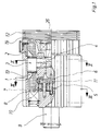
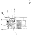
- the electric motor consists of a radially outside in the housing 1 fixed ring-shaped stator 3 and one radially inside coaxial rotor 4.
- the rotor 4 is an integral part of the motor output shaft. to which in turn forms a transmission input Sun gear 5 is connected. On the gear part opposite end of the rotor 4, this is in a housing 1 tightly closing motor end flange 2 roller bearings.
- the sun gear 5 drives in one within the transmission Planet carrier 6 mounted and in a in the housing 1st rigidly fixed ring gear 7 meshing planet gears 8.
- the free end of the planet carrier located away from the motor 6 serves as the transmission output shaft 9.
- the planet gear carrier 6 is on roller bearings 10 and 11 in the gear housing 1 rotatably axially fixed.
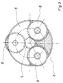
- the end of the planet carrier carrying the planet gears 8 6 is closed in the basic form as a kind Disc with recesses for receiving the sun gear 5 on the one hand and the planet gears 8 on the other hand as the illustration in Fig. 3 shows quite clearly.
- the electric motor part Due to the complete oil filling of the transmission and engine is an excellent damping of running noise of the transmission and on the other hand one especially for the electric motor part reaches the desired high heat dissipation. Due to the good heat dissipation, the electric motor part can be spatially be reduced in size, since only correspondingly smaller Heat dissipation surfaces are required.
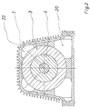
- the Stator 3 radially on the outside only partially in the housing 2 on. In the remaining free spaces 20 oil can Flow around stator 3 with its windings for cooling.
- the rotor 4 is open radially on the outside with a helical shape extending into the axial end faces of the rotor 4 Oil delivery groove 26 may be provided. When turning the rotor 4 promotes this groove 26 each oil from an axial side of the Rotors 4 to the other end.
- the direction of funding depends thereby from the direction of rotation of the rotor 4.
- For the aimed Oil flow is the respective direction of delivery indifferent. It is only important that an oil circulation occurs at all.
- the housing 2 only faces outwards resting parts that are easy to seal. Only on the gearbox side there must be a usual barrel seal between the transmission output shaft 9 and the stationary Outside wall of the housing 1 can be provided.
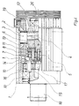
- the two-stage motor transmission shown in FIG. 4 is basically constructed in the same way as that before single-stage gearbox described. Same parts are there therefore also called the same. Many have with the transmission Parts even the same dimensions in both cases. There are this, for example, the housing 1 with the ring gear 7, the planet gears 8 and the sun gear 5 and the motor end flange 2. For the inclusion of the second gear stage is an additional transmission output flange to the housing 1 l'applied.
- This transmission output flange 1 ' is partly in the housing 1 inserted.
- the 14 in the planet carrier planetary gears 15 guided in the second gear stage engage a ring gear 16, which is inserted into the housing 1 Area of the transmission output flange 1 '.
- the part of the planet carrier 14 lying on the motor side second gear stage is directly in via a roller bearing 10 the housing 1 stored. This makes it extremely stable Bearing of the transmission output shaft 18 of the second gear stage reached. Contributes to such stable storage also the position of the ring gear 16 of the second gear stage inside the housing 1 at.
- the second gear stage is driven by a sun gear 17, to the planet carrier 6 of the first gear stage is connected.
- the planet carrier 14 of the second The gear stage forms the gear output side as in the case of the single-stage version, the transmission output shaft, the is designated 18 in the two-stage version.
- the two-stage engine transmission differs practically solely by using the gearbox output flange scheduled second stage of the one-stage execution, the therefore an unchanged basic part of the two-stage version is.
- an oil cooler 12 may become simple on the motor end flange of the one- or two-stage Motor gearbox attached.
- a connection for the oil flow serves a connection opening 19th
- the wheel disk 21 additionally as a handwheel area 25 for turning the Engine output shaft to be formed by hand.
Landscapes
- Engineering & Computer Science (AREA)
- Power Engineering (AREA)
- Connection Of Motors, Electrical Generators, Mechanical Devices, And The Like (AREA)
- Hybrid Electric Vehicles (AREA)
Claims (16)
- Ensemble moteur-boíte de vitesses, en particulier pour l'entraínement d'un ascenseur, comprenant un moteur électrique agissant sur une boíte de vitesses (1) à roue dentée planétaire, dans lequel la boíte de vitesses (1) et le moteur (2) sont disposés dans un espace commun rempli d'huile, et dans lequel l'arbre de sortie du moteur entraíne, par l'intermédiaire d'une roue solaire (5) fixée solidement à celui-ci, dans une couronne de train planétaire (7) extérieure fixée au carter, des roues planétaires (8) s'engrenant, montées dans un support de roue planétaire (6),
caractérisé en ce que
l'espace commun, dépourvu de cloison de séparation, pour la partie boíte de vitesses et moteur (1, 2), est complètement rempli d'huile et en ce que le support de roue planétaire (6) est un disque fermé de contour extérieur circulaire et ne possède que des évidements étroitement limités pour la roue solaire (5) et les roues planétaires (8), dont l'évidement pour la roue solaire (5), dans lequel débouchent les évidements pour les roues planétaires (6), présente un contour extérieur également circulaire, et en ce qu'en outre, les centres des deux contours extérieurs circulaires se trouvent conjointement sur l'axe de rotation du support de roue planétaire (6). - Ensemble moteur-boíte de vitesses selon la revendication 1,
caractérisé en ce que
la denture de la boíte de vitesses est formée avec un petit module m correspondant à environ la largeur de la roue dentée divisée par 40. - Ensemble moteur-boíte de vitesses selon l'une quelconque des revendications précédentes,
caractérisé en ce que
celui-ci possède un refroidisseur d'huile (12) ou au moins des raccordements (19) pour un tel refroidisseur, afin de refroidir ultérieurement l'huile dans ce refroidisseur par circulation forcée. - Ensemble moteur-boíte de vitesses selon l'une quelconque des revendications précédentes,
caractérisé en ce que
la boíte à engrenages planétaires est formée en plusieurs étages avec à chaque fois des couronnes de trains planétaires (7, 16) fixées au carter et se trouvant à l'extérieur, et à chaque fois, des supports de roue planétaire (6, 14) correspondant aux caractéristiques de la revendication 1. - Ensemble moteur-boíte de vitesses selon l'une quelconque des revendications précédentes,
caractérisé en ce que
le moteur électrique possède un stator extérieur (3) avec des enroulements orientés axialement, qui viennent en prise par l'arrière radialement avec la couronne de train planétaire (7) de la boíte à engrenages planétaires tournée vers le moteur électrique. - Ensemble moteur-boíte de vitesses selon la revendication 5,
caractérisé en ce que
le stator (3) du moteur électrique (2) possède, dans des zones partielles de sa périphérie extérieure, des espaces libres (20) s'étendant axialement, pouvant être parcourus par l'huile de refroidissement se trouvant dans le carter du moteur. - Ensemble moteur-boíte de vitesses selon l'une quelconque des revendications précédentes,
caractérisé en ce que
le rotor (4) du moteur électrique (2) est pourvu, radialement vers l'extérieur, d'au moins une gorge (26) de guidage de l'huile s'étendant à chaque fois, de manière ouverte, en spirale, aux extrémités axiales du rotor (4). - Ensemble moteur-boíte de vitesses selon l'une quelconque des revendications précédentes,
caractérisé en ce que
l'arbre de sortie (9, 18) de la boíte à engrenages planétaires est formé d'une seule pièce avec le support planétaire (6) ou (14) voisin de celui-ci. - Ensemble moteur-boíte de vitesses selon l'une quelconque des revendications précédentes, avec une partie boíte de vitesses à un étage,
caractérisé en ce que
cet ensemble moteur-boíte de vitesses se compose d'un carter (1) recevant l'ensemble de la partie boíte de vitesses ainsi qu'une partie du moteur et une bride de fermeture du moteur (2) supportant l'extrémité libre de l'arbre de sortie du moteur et recevant la partie restante du moteur. - Ensemble moteur-boíte de vitesses selon l'une quelconque des revendications 1 à 8, avec une partie de boíte de vitesses à deux étages,
caractérisé en ce que
le deuxième étage de la partie de boíte de vitesses peut être placé dans une bride de sortie de boíte de vitesses (1'), qui peut être poussée axialement sur une zone partielle si loin dans un carter non modifié (1) d'un ensemble moteur-boíte de vitesses à un étage, que les roues planétaires (15) du deuxième étage de boíte de vitesses se trouvent dans cette zone partielle. - Ensemble moteur-boíte de vitesses selon la revendication 10,
caractérisé en ce que
le support de roue planétaire (14) du deuxième étage de boíte de vitesses est monté sur roulement du côté du moteur directement dans le carter (1) du premier étage de boíte de vitesse. - Ensemble moteur-boíte de vitesses selon l'une quelconque des revendications précédentes, en particulier en tant que boíte de vitesses d'ascenseur,
caractérisé en ce que
l'arbre de sortie du moteur relié au rotor (4) du moteur électrique est poussé à travers la bride de fermeture du moteur (2) vers l'extérieur, et est pourvu d'un disque de roue (21) servant de partie d'un frein et ou d'un volant à main. - Ensemble moteur-boíte de vitesses selon la revendication 12,
caractérisé en ce que
le frein est un frein à mâchoire ou à disque. - Ensemble moteur-boíte de vitesses selon la revendication 12 ou 13,
caractérisé en ce qu'entre le disque de roue (21) et la bride de fermeture du moteur (2), est intégré un tachymètre (22). - Utilisation d'un ensemble moteur-boíte de vitesses, en particulier selon l'une quelconque des revendications précédentes, comprenant un moteur électrique (2) agissant sur une boíte de vitesses à roue dentée planétaire (1), dans lequel la boíte de vitesses (1) et le moteur sont disposés dans un espace commun complètement rempli d'huile et dépourvu de cloison, pour l'entraínement d'un ascenseur.
- Utilisation d'un ensemble moteur-boíte de vitesses selon la revendication 15, dans lequel la denture de la boíte de vitesses (1) est formée avec un petit module (m) d'environ la largeur de la roue dentée divisée par 40.
Applications Claiming Priority (3)
| Application Number | Priority Date | Filing Date | Title |
|---|---|---|---|
| DE4440565 | 1994-11-12 | ||
| DE4440565A DE4440565A1 (de) | 1994-11-12 | 1994-11-12 | Motorgetriebe |
| PCT/DE1995/001496 WO1996015575A1 (fr) | 1994-11-12 | 1995-10-24 | Ensemble moteur-reducteur |
Publications (2)
| Publication Number | Publication Date |
|---|---|
| EP0791237A1 EP0791237A1 (fr) | 1997-08-27 |
| EP0791237B1 true EP0791237B1 (fr) | 1998-09-23 |
Family
ID=6533233
Family Applications (1)
| Application Number | Title | Priority Date | Filing Date |
|---|---|---|---|
| EP95935813A Expired - Lifetime EP0791237B1 (fr) | 1994-11-12 | 1995-10-24 | Ensemble moteur-reducteur |
Country Status (3)
| Country | Link |
|---|---|
| EP (1) | EP0791237B1 (fr) |
| DE (2) | DE4440565A1 (fr) |
| WO (1) | WO1996015575A1 (fr) |
Cited By (1)
| Publication number | Priority date | Publication date | Assignee | Title |
|---|---|---|---|---|
| DE102010025352B4 (de) | 2010-06-28 | 2019-12-24 | Audi Ag | Verfahren zum Herstellen einer elektrischen Maschine eines Kraftwagens |
Families Citing this family (3)
| Publication number | Priority date | Publication date | Assignee | Title |
|---|---|---|---|---|
| JP3560947B2 (ja) * | 2001-11-06 | 2004-09-02 | 株式会社日立製作所 | 回転電機 |
| DE102012018033B4 (de) | 2012-09-13 | 2024-07-18 | Audi Ag | Kraftwagen |
| DE102014221303B4 (de) * | 2014-10-13 | 2016-08-18 | Schaeffler Technologies AG & Co. KG | Elektrische Maschine mit integriertem Wärmepuffer sowie Antriebseinheit mit einer solchen elektronischen Maschine |
Family Cites Families (16)
| Publication number | Priority date | Publication date | Assignee | Title |
|---|---|---|---|---|
| US511090A (en) * | 1893-12-19 | Furnace-tap | ||
| US511089A (en) * | 1893-12-19 | Convertible case and display-stand for charts | ||
| DE857232C (de) * | 1951-04-12 | 1952-11-27 | Siemens Ag | Doppelwandiges Staendergehaeuse fuer fluessigkeitsgekuehlte elektrische Maschinen |
| DE1879520U (de) * | 1961-04-04 | 1963-09-19 | Robert Hanning | Mit einem zweistufigen planetengetriebe kombinierter elektromotor. |
| DE1183589B (de) * | 1962-11-09 | 1964-12-17 | Curt Stoll K G | Mittels Elektromotor ueber ein Getriebe angetriebenes Arbeitsgeraet |
| DE1218601B (de) * | 1964-07-02 | 1966-06-08 | Siemens Ag | Synchron-Kleinstmotor mit polarisiertem Laeufer und angebautem Getriebe |
| DE1613220A1 (de) * | 1967-04-07 | 1970-05-21 | Licentia Gmbh | Getriebemotor |
| DE1613423A1 (de) * | 1967-09-29 | 1972-01-27 | Siemens Ag | In seiner Drehzahl steuerbarer Elektromotor |
| DE1613290A1 (de) * | 1967-12-01 | 1971-01-28 | Licentia Gmbh | Elektromotorischer Antrieb,insbesondere fuer eine Waschmaschine |
| DE2044295A1 (de) * | 1970-09-08 | 1972-03-16 | Allweiler Ag | Stopfbuchsloses Pumpenaggregat |
| DE2538561C3 (de) * | 1975-08-29 | 1980-06-04 | Arnold 7312 Kirchheim Mueller | Induktionsmotor |
| JPS58140468A (ja) * | 1982-02-17 | 1983-08-20 | Hitachi Ltd | リダクシヨンスタ−タ |
| JP2769323B2 (ja) * | 1988-06-29 | 1998-06-25 | アイシン・エィ・ダブリュ株式会社 | 減速機付モータ駆動装置及び電動車両 |
| DE8811966U1 (de) * | 1988-09-21 | 1989-07-20 | Siemens Ag, 1000 Berlin Und 8000 Muenchen | Elektromotorischer Antrieb, insbesondere Verstellantrieb für ein Kraftfahrzeug |
| DE4029373A1 (de) * | 1990-09-15 | 1992-03-19 | Ford Werke Ag | Anlaufscheibenanordnung fuer planetenraeder eines planetenradtraegers |
| DE4134553A1 (de) * | 1991-10-20 | 1992-03-05 | Bernhard Orlowski | Von einem elektromotor angetriebenes planeten-zahnradgetriebe |
-
1994
- 1994-11-12 DE DE4440565A patent/DE4440565A1/de not_active Withdrawn
-
1995
- 1995-10-24 EP EP95935813A patent/EP0791237B1/fr not_active Expired - Lifetime
- 1995-10-24 DE DE59503732T patent/DE59503732D1/de not_active Expired - Fee Related
- 1995-10-24 WO PCT/DE1995/001496 patent/WO1996015575A1/fr not_active Ceased
Cited By (1)
| Publication number | Priority date | Publication date | Assignee | Title |
|---|---|---|---|---|
| DE102010025352B4 (de) | 2010-06-28 | 2019-12-24 | Audi Ag | Verfahren zum Herstellen einer elektrischen Maschine eines Kraftwagens |
Also Published As
| Publication number | Publication date |
|---|---|
| EP0791237A1 (fr) | 1997-08-27 |
| DE59503732D1 (de) | 1998-10-29 |
| DE4440565A1 (de) | 1996-05-15 |
| WO1996015575A1 (fr) | 1996-05-23 |
Similar Documents
| Publication | Publication Date | Title |
|---|---|---|
| DE4309559B4 (de) | Achsversetztes Winkelgetriebe | |
| EP0602491B1 (fr) | Installation de transmission et de compression | |
| DE112008000344B4 (de) | Leistungsübertragungsvorrichtung und Herstellungsverfahren dafür | |
| EP2047143B1 (fr) | Entrainement de pompe d'une boite de vitesses automatique | |
| EP1098063B1 (fr) | Moteur tubulaire | |
| EP1110011B1 (fr) | Reducteur a plusieurs etages de pignons cylindriques | |
| DE102005018956A1 (de) | Vorrichtung zur Nockenwellenverstellung einer Brennkraftmaschine | |
| DE4412898A1 (de) | Planetengetriebe mit integriertem Elektromotor | |
| EP1046838A2 (fr) | Transmission pour éoliennes | |
| DE19841159A1 (de) | Antriebsanordnung für ein Kraftfahrzeug | |
| DE102016118336A1 (de) | Antriebsmechanismus | |
| EP1485636B1 (fr) | Mecanisme de commande | |
| DE102016118877B4 (de) | Mechanische Getriebeanordnung | |
| KR960706449A (ko) | 승강장치를 위한 구동장치 | |
| DE202022000784U1 (de) | Rotierende elektrische Maschine in Außenläuferbauweise mit integriertem Umlaufgetriebe | |
| WO2019197251A1 (fr) | Palier conçu pour un module hybride | |
| DE10004373A1 (de) | Antrieb einer Schraubenspindelpumpe | |
| EP0791237B1 (fr) | Ensemble moteur-reducteur | |
| WO2017092740A1 (fr) | Transmission planétaire pour une unité d'entraînement de véhicule automobile | |
| DE10149255B4 (de) | Wellgetriebe mit Planetenradantrieb | |
| DE19923877A1 (de) | Motor-Getriebe-Einheit | |
| DE10101669A1 (de) | Elektrischer Einzelradantrieb | |
| WO2019067122A1 (fr) | Commande de balayage avec ensemble réducteur intégré | |
| EP3478606B1 (fr) | Moteur-tambour à logement de transmission alternatif | |
| DE102015201158A1 (de) | Aktuatoreinheit |
Legal Events
| Date | Code | Title | Description |
|---|---|---|---|
| PUAI | Public reference made under article 153(3) epc to a published international application that has entered the european phase |
Free format text: ORIGINAL CODE: 0009012 |
|
| 17P | Request for examination filed |
Effective date: 19970306 |
|
| AK | Designated contracting states |
Kind code of ref document: A1 Designated state(s): CH DE ES GB IT LI SE |
|
| 17Q | First examination report despatched |
Effective date: 19971020 |
|
| GRAG | Despatch of communication of intention to grant |
Free format text: ORIGINAL CODE: EPIDOS AGRA |
|
| GRAG | Despatch of communication of intention to grant |
Free format text: ORIGINAL CODE: EPIDOS AGRA |
|
| GRAH | Despatch of communication of intention to grant a patent |
Free format text: ORIGINAL CODE: EPIDOS IGRA |
|
| GRAH | Despatch of communication of intention to grant a patent |
Free format text: ORIGINAL CODE: EPIDOS IGRA |
|
| GRAA | (expected) grant |
Free format text: ORIGINAL CODE: 0009210 |
|
| AK | Designated contracting states |
Kind code of ref document: B1 Designated state(s): CH DE ES GB IT LI SE |
|
| PG25 | Lapsed in a contracting state [announced via postgrant information from national office to epo] |
Ref country code: ES Free format text: THE PATENT HAS BEEN ANNULLED BY A DECISION OF A NATIONAL AUTHORITY Effective date: 19980923 |
|
| REG | Reference to a national code |
Ref country code: CH Ref legal event code: EP |
|
| REF | Corresponds to: |
Ref document number: 59503732 Country of ref document: DE Date of ref document: 19981029 |
|
| GBT | Gb: translation of ep patent filed (gb section 77(6)(a)/1977) |
Effective date: 19981009 |
|
| PG25 | Lapsed in a contracting state [announced via postgrant information from national office to epo] |
Ref country code: SE Free format text: LAPSE BECAUSE OF FAILURE TO SUBMIT A TRANSLATION OF THE DESCRIPTION OR TO PAY THE FEE WITHIN THE PRESCRIBED TIME-LIMIT Effective date: 19981223 |
|
| PLBE | No opposition filed within time limit |
Free format text: ORIGINAL CODE: 0009261 |
|
| STAA | Information on the status of an ep patent application or granted ep patent |
Free format text: STATUS: NO OPPOSITION FILED WITHIN TIME LIMIT |
|
| 26N | No opposition filed | ||
| PG25 | Lapsed in a contracting state [announced via postgrant information from national office to epo] |
Ref country code: GB Free format text: LAPSE BECAUSE OF NON-PAYMENT OF DUE FEES Effective date: 19991024 |
|
| PGFP | Annual fee paid to national office [announced via postgrant information from national office to epo] |
Ref country code: DE Payment date: 19991112 Year of fee payment: 5 |
|
| PGFP | Annual fee paid to national office [announced via postgrant information from national office to epo] |
Ref country code: CH Payment date: 19991116 Year of fee payment: 5 |
|
| GBPC | Gb: european patent ceased through non-payment of renewal fee |
Effective date: 19991024 |
|
| PG25 | Lapsed in a contracting state [announced via postgrant information from national office to epo] |
Ref country code: LI Free format text: LAPSE BECAUSE OF NON-PAYMENT OF DUE FEES Effective date: 20001031 Ref country code: CH Free format text: LAPSE BECAUSE OF NON-PAYMENT OF DUE FEES Effective date: 20001031 |
|
| REG | Reference to a national code |
Ref country code: CH Ref legal event code: PL |
|
| PG25 | Lapsed in a contracting state [announced via postgrant information from national office to epo] |
Ref country code: DE Free format text: LAPSE BECAUSE OF NON-PAYMENT OF DUE FEES Effective date: 20010703 |
|
| PG25 | Lapsed in a contracting state [announced via postgrant information from national office to epo] |
Ref country code: IT Free format text: LAPSE BECAUSE OF NON-PAYMENT OF DUE FEES;WARNING: LAPSES OF ITALIAN PATENTS WITH EFFECTIVE DATE BEFORE 2007 MAY HAVE OCCURRED AT ANY TIME BEFORE 2007. THE CORRECT EFFECTIVE DATE MAY BE DIFFERENT FROM THE ONE RECORDED. Effective date: 20051024 |