EP0790488B1 - Levier de commande à positionner en rotation tri-axiale - Google Patents
Levier de commande à positionner en rotation tri-axiale Download PDFInfo
- Publication number
- EP0790488B1 EP0790488B1 EP97101788A EP97101788A EP0790488B1 EP 0790488 B1 EP0790488 B1 EP 0790488B1 EP 97101788 A EP97101788 A EP 97101788A EP 97101788 A EP97101788 A EP 97101788A EP 0790488 B1 EP0790488 B1 EP 0790488B1
- Authority
- EP
- European Patent Office
- Prior art keywords
- control stick
- light
- light beams
- detector
- radiator
- Prior art date
- Legal status (The legal status is an assumption and is not a legal conclusion. Google has not performed a legal analysis and makes no representation as to the accuracy of the status listed.)
- Expired - Lifetime
Links
- 238000011156 evaluation Methods 0.000 claims description 9
- 230000005693 optoelectronics Effects 0.000 claims description 5
- 238000010276 construction Methods 0.000 description 5
- 238000009434 installation Methods 0.000 description 3
- 238000005259 measurement Methods 0.000 description 3
- 238000004088 simulation Methods 0.000 description 3
- 230000005855 radiation Effects 0.000 description 2
- 238000012937 correction Methods 0.000 description 1
- 230000001419 dependent effect Effects 0.000 description 1
- 238000013461 design Methods 0.000 description 1
- 230000001939 inductive effect Effects 0.000 description 1
- 238000004519 manufacturing process Methods 0.000 description 1
- 238000012545 processing Methods 0.000 description 1
Images
Classifications
-
- G—PHYSICS
- G06—COMPUTING; CALCULATING OR COUNTING
- G06F—ELECTRIC DIGITAL DATA PROCESSING
- G06F3/00—Input arrangements for transferring data to be processed into a form capable of being handled by the computer; Output arrangements for transferring data from processing unit to output unit, e.g. interface arrangements
- G06F3/01—Input arrangements or combined input and output arrangements for interaction between user and computer
- G06F3/03—Arrangements for converting the position or the displacement of a member into a coded form
- G06F3/0304—Detection arrangements using opto-electronic means
- G06F3/0325—Detection arrangements using opto-electronic means using a plurality of light emitters or reflectors or a plurality of detectors forming a reference frame from which to derive the orientation of the object, e.g. by triangulation or on the basis of reference deformation in the picked up image
-
- G—PHYSICS
- G01—MEASURING; TESTING
- G01D—MEASURING NOT SPECIALLY ADAPTED FOR A SPECIFIC VARIABLE; ARRANGEMENTS FOR MEASURING TWO OR MORE VARIABLES NOT COVERED IN A SINGLE OTHER SUBCLASS; TARIFF METERING APPARATUS; MEASURING OR TESTING NOT OTHERWISE PROVIDED FOR
- G01D5/00—Mechanical means for transferring the output of a sensing member; Means for converting the output of a sensing member to another variable where the form or nature of the sensing member does not constrain the means for converting; Transducers not specially adapted for a specific variable
- G01D5/26—Mechanical means for transferring the output of a sensing member; Means for converting the output of a sensing member to another variable where the form or nature of the sensing member does not constrain the means for converting; Transducers not specially adapted for a specific variable characterised by optical transfer means, i.e. using infrared, visible, or ultraviolet light
-
- G—PHYSICS
- G05—CONTROLLING; REGULATING
- G05G—CONTROL DEVICES OR SYSTEMS INSOFAR AS CHARACTERISED BY MECHANICAL FEATURES ONLY
- G05G9/00—Manually-actuated control mechanisms provided with one single controlling member co-operating with two or more controlled members, e.g. selectively, simultaneously
- G05G9/02—Manually-actuated control mechanisms provided with one single controlling member co-operating with two or more controlled members, e.g. selectively, simultaneously the controlling member being movable in different independent ways, movement in each individual way actuating one controlled member only
- G05G9/04—Manually-actuated control mechanisms provided with one single controlling member co-operating with two or more controlled members, e.g. selectively, simultaneously the controlling member being movable in different independent ways, movement in each individual way actuating one controlled member only in which movement in two or more ways can occur simultaneously
- G05G9/047—Manually-actuated control mechanisms provided with one single controlling member co-operating with two or more controlled members, e.g. selectively, simultaneously the controlling member being movable in different independent ways, movement in each individual way actuating one controlled member only in which movement in two or more ways can occur simultaneously the controlling member being movable by hand about orthogonal axes, e.g. joysticks
- G05G2009/0474—Manually-actuated control mechanisms provided with one single controlling member co-operating with two or more controlled members, e.g. selectively, simultaneously the controlling member being movable in different independent ways, movement in each individual way actuating one controlled member only in which movement in two or more ways can occur simultaneously the controlling member being movable by hand about orthogonal axes, e.g. joysticks characterised by means converting mechanical movement into electric signals
- G05G2009/04759—Light-sensitive detector, e.g. photoelectric
-
- G—PHYSICS
- G05—CONTROLLING; REGULATING
- G05G—CONTROL DEVICES OR SYSTEMS INSOFAR AS CHARACTERISED BY MECHANICAL FEATURES ONLY
- G05G9/00—Manually-actuated control mechanisms provided with one single controlling member co-operating with two or more controlled members, e.g. selectively, simultaneously
- G05G9/02—Manually-actuated control mechanisms provided with one single controlling member co-operating with two or more controlled members, e.g. selectively, simultaneously the controlling member being movable in different independent ways, movement in each individual way actuating one controlled member only
- G05G9/04—Manually-actuated control mechanisms provided with one single controlling member co-operating with two or more controlled members, e.g. selectively, simultaneously the controlling member being movable in different independent ways, movement in each individual way actuating one controlled member only in which movement in two or more ways can occur simultaneously
- G05G9/047—Manually-actuated control mechanisms provided with one single controlling member co-operating with two or more controlled members, e.g. selectively, simultaneously the controlling member being movable in different independent ways, movement in each individual way actuating one controlled member only in which movement in two or more ways can occur simultaneously the controlling member being movable by hand about orthogonal axes, e.g. joysticks
- G05G2009/04781—Manually-actuated control mechanisms provided with one single controlling member co-operating with two or more controlled members, e.g. selectively, simultaneously the controlling member being movable in different independent ways, movement in each individual way actuating one controlled member only in which movement in two or more ways can occur simultaneously the controlling member being movable by hand about orthogonal axes, e.g. joysticks with additional rotation of the controlling member
-
- Y—GENERAL TAGGING OF NEW TECHNOLOGICAL DEVELOPMENTS; GENERAL TAGGING OF CROSS-SECTIONAL TECHNOLOGIES SPANNING OVER SEVERAL SECTIONS OF THE IPC; TECHNICAL SUBJECTS COVERED BY FORMER USPC CROSS-REFERENCE ART COLLECTIONS [XRACs] AND DIGESTS
- Y10—TECHNICAL SUBJECTS COVERED BY FORMER USPC
- Y10T—TECHNICAL SUBJECTS COVERED BY FORMER US CLASSIFICATION
- Y10T74/00—Machine element or mechanism
- Y10T74/20—Control lever and linkage systems
- Y10T74/20012—Multiple controlled elements
- Y10T74/20201—Control moves in two planes
Definitions
- the invention relates to a three-axis rotationally positionable Joysticks, in particular for a helicopter, with an electronic Sensor for determining the stick position.
- US Pat. No. 3,432,671 is an optoelectronic position transmitter known in which a rectangular light field over a biaxial tiltable deflecting mirror on one of four arranged in a cross shape Photo cell existing sensor part shown and from the size the swiveled position of the deflecting mirror is calculated with respect to the two axes of rotation.
- Such a sensor is however, to determine the position of a three-axis adjustable joystick unsuitable and still has the disadvantage of a limited Accuracy of measurement because external interference, e.g. local fluctuations in the lighting intensity, falsifying the measurement result impact.
- US-A-5 181 079 shows an opto-electronic measuring arrangement in which three scanning beams are necessary to determine the position.
- WO 97/05567 shows a three-axis rotary positioner Computer joystick with an opto-electronic which determines the stick position Sensor.
- the object of the invention is a control stick of the aforementioned Type in such a way that in a structurally simple, weight and space-saving Way an extremely accurate and reliable position measurement regarding all three axes of movement of the joystick is guaranteed.
- a special one simple, mathematical connection between the position coordinates of the two light beam light spots on the detector mosaic and the roll, pitch and yaw position of the joystick results from the fact that one of the two light beams is coaxial a stick axis of rotation is aligned.
- the detector mosaic is used to save light-sensitive detector area from two separate ones Detector fields, each of which is only in the beam path one of the two light rays is located.
- the detector mosaic is or are the detector fields just trained.
- the mutual The position of the two light beams and possibly the detector fields is dependent on the installation conditions practically arbitrary. So the two rays of light inclined, perpendicular to each other be aligned, which is recommended for multiple redundant sensors, in general, however, one becomes essentially parallel mutual alignment of the two light beams is preferred.
- the rays of light are particularly simple in terms of construction by two light-emitting diodes attached to the control stick generated. Alternatively, however, it is also possible to generate the double jet a light emitting single diode with a to provide downstream radiation dividers.
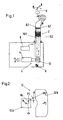
- a joystick 2 around a fictitious pivot point G. triaxial, namely on the one hand around the vertical axis H and on the other hand in Longitudinal and transverse control direction N or R limited rotational position and contains an opto-electronic sensor, designated 4 in total, which measures the stick position in all three axes and corresponding ones electrical control commands n, r and h for a subordinate, fly-by-wire controlled blade angle adjustment system of a helicopter and provides for control force simulation of the joystick 2.
- the sensor 4 contains two attached to the inside of the control stick 2 a power supply 6 connected laser diodes 8.1 and 8.2 inclusive a focusing device for generating two spatially apart separate, sharply focused laser light beams 10.1 and 10.2, which run parallel to each other and of which the one - 10.1 - is aligned with the vertical axis H.
- a pair of diodes can also use a single diode to generate the double beam 10 downstream radiation splitter may be provided.
- a housing-fixed detector mosaic 12 in the form of a high-resolution, laser light-sensitive CCD detector, which lies over the entire adjustment range of the joystick 2 in the beam path of the two light beams 10.1 and 10.2 and the position of the light points P 1 generated by them on the detector surface , P 2 is determined and the corresponding X and Y coordinates are transferred to a downstream evaluation electronics 14, where they are converted into the roll, pitch and yaw commands r, n and h of the control stick 2 in the manner explained below.
- the control stick 2 pivots about each of its three axes is so that the light spot P 1 to point P 1 'and the light spot P 2 to point P 2 ' migrates (see Fig. 2).
- the detector mosaic 12 digitally detects the changes in the light spot coordinates.
- the light beams 10.1 and 10.2 can also have any other desired orientation to one another and to the vertical axis H.
- all that is required to adjust the sensor 2 is to store the coordinates of the two light spots P 1 and P 2 in the zero position and in a second control stick position in the evaluation electronics 14, which position is twisted only about the vertical axis H, and the Modify the above-mentioned relationships between the measured values of the detector mosaic 12 and the output signals n, r and h in a corresponding manner.
- the detector mosaic 12 is of flat design. The consequence of this is that the distance between the two light spots P 1 and P 2 changes slightly when the control stick 2 is pivoted, which can be taken into account by corresponding correction factors, for example, stored in a table in the evaluation electronics 14. If the adjustment movements of the control stick 2 are smaller than the mutual distance of the light beams 10.1 and 10.2, the light spots P 1 and P 2 each remain in separate surface areas. In order to save light-sensitive detector area, the detector mosaic 12 is therefore composed of two mutually separate detector fields 12A and 12B, which correspond in shape and size to the parts of the area migrated by the light spots P 1 and P 2 .
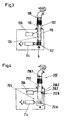
- a corresponding variety of laser diodes 108 generates a total of four double beams 110 which each on one of four around the vertical axis H of the control stick 102 grouped detector mosaics 112.
- the location coordinates of the the individual detector mosaics 112 each of the resulting light spot pairs are transmitted to a common evaluation electronics 114, where from them the roll, pitch and yaw position of the joystick 102 is calculated.
- the evaluation electronics 114 is designed so that the Sensor fully functional in the event of failure of individual sensor components remains. Otherwise, the construction and operation is the same as the Embodiment according to FIGS. 1 and 2.
- the control stick 202 of FIG. 4, in which the individual components are characterized by a reference number increased by 200 differs from the previous exemplary embodiments by a other mutual orientation of the light beam pair 210.
- a light beam 210.1 emitted by the laser light diode 208.1 remains unchanged runs in the direction of the joystick vertical axis, is the second of the light beam 210.2 generated by the laser light diode 208.2 essentially radially to the joystick 202 on the side next to the joystick in this case 202 detector field 212B attached to the housing.
- the detector field 212B in the same way as in the first embodiment in the plane of the detector field 212A laterally arranged next to this and a deflecting mirror instead of the detector field 212B be provided, the laterally directed laser light beam 210.2 deflected down to the detector field 212B.
- the evaluation electronics work in a different way on the basis of appropriately modified computing operations for implementation the light spot position coordinates in the position signals r, n and h des Joystick 202. Otherwise, the construction and operation is the same as in the embodiments described above.
Landscapes
- Engineering & Computer Science (AREA)
- Physics & Mathematics (AREA)
- General Physics & Mathematics (AREA)
- General Engineering & Computer Science (AREA)
- Theoretical Computer Science (AREA)
- Human Computer Interaction (AREA)
- Position Input By Displaying (AREA)
- Mechanical Control Devices (AREA)
- Length Measuring Devices By Optical Means (AREA)
Claims (9)
- Levier de commande (2) à trois axes notamment pour un hélicoptère comportant un capteur optoélectronique (4) déterminant la position du levier de commande, ce capteur comportant :un émetteur (8) solidaire en mouvement du levier de commande et émettant précisément deux faisceaux lumineux (10.1, 10.2) séparés l'un de l'autre dans l'espace,une mosaïque de détecteur (12) photosensible, fixe, située dans toute la plage de réglage du levier de commande dans le chemin des deux faisceaux lumineux pour déterminer les coordonnées de position des deux taches lumineuses (P1, P2) générées par les rayons lumineux sur la mosaïque de détecteur, etun circuit d'exploitation (14) qui, à partir des coordonnées de position des deux taches lumineuses, détermine la position de roulis, de tangage et de lacet (r, n, h) du levier de commande.
- Levier de commande selon la revendication 1,
caractérisé en ce que
l'un des deux rayons lumineux (10.1) est aligné sur l'axe de rotation (H) du levier de commande. - Levier de commande selon l'une quelconque des revendications précédentes,
caractérisé en ce que
la mosaïque de détecteur (12) se compose de deux champs de détecteur séparés (12A, 12B) situés chacun dans le chemin de l'un des faisceaux lumineux (10). - Levier de commande selon la revendication 3,
caractérisé en ce que
les deux champs de détecteur (12A, 12B) se trouvent dans un plan commun. - Levier de commande selon l'une quelconque des revendications 3 ou 4,
caractérisé en ce que
les deux faisceaux lumineux (210) sont inclinés l'un par rapport à l'autre et de préférence perpendiculaires. - Levier de commande selon l'une quelconque des revendications 1 à 4,
caractérisé en ce que
les deux faisceaux lumineux (10) sont parallèles l'un à l'autre. - Levier de commande selon l'une quelconque des revendications précédentes,
caractérisé par
un émetteur (8) formé de deux diodes photo-émissives (8.1, 8.2) fixées au levier de commande (2). - Levier de commande selon l'une quelconque des revendications 1 à 6,
caractérisé par
un émetteur (8) formé d'une seule diode photo-émissive et d'un diviseur de faisceau en aval de celle-ci. - Levier de commande selon l'une quelconque des revendications précédentes
caractérisé en ce que
l'émetteur (8) est un émetteur de lumière laser.
Applications Claiming Priority (2)
| Application Number | Priority Date | Filing Date | Title |
|---|---|---|---|
| DE19605573A DE19605573C2 (de) | 1996-02-15 | 1996-02-15 | Dreiachsig drehpositionierbarer Steuerknüppel |
| DE19605573 | 1996-02-15 |
Publications (3)
| Publication Number | Publication Date |
|---|---|
| EP0790488A2 EP0790488A2 (fr) | 1997-08-20 |
| EP0790488A3 EP0790488A3 (fr) | 1999-05-19 |
| EP0790488B1 true EP0790488B1 (fr) | 2003-05-02 |
Family
ID=7785464
Family Applications (1)
| Application Number | Title | Priority Date | Filing Date |
|---|---|---|---|
| EP97101788A Expired - Lifetime EP0790488B1 (fr) | 1996-02-15 | 1997-02-05 | Levier de commande à positionner en rotation tri-axiale |
Country Status (3)
| Country | Link |
|---|---|
| US (1) | US6081257A (fr) |
| EP (1) | EP0790488B1 (fr) |
| DE (2) | DE19605573C2 (fr) |
Families Citing this family (34)
| Publication number | Priority date | Publication date | Assignee | Title |
|---|---|---|---|---|
| DE19821403B4 (de) | 1998-05-13 | 2005-07-28 | ZF Lemförder Metallwaren AG | Wählvorrichtung für ein Fahrzeuggetriebe |
| US8788092B2 (en) | 2000-01-24 | 2014-07-22 | Irobot Corporation | Obstacle following sensor scheme for a mobile robot |
| US8412377B2 (en) | 2000-01-24 | 2013-04-02 | Irobot Corporation | Obstacle following sensor scheme for a mobile robot |
| US6956348B2 (en) | 2004-01-28 | 2005-10-18 | Irobot Corporation | Debris sensor for cleaning apparatus |
| US6690134B1 (en) | 2001-01-24 | 2004-02-10 | Irobot Corporation | Method and system for robot localization and confinement |
| US7571511B2 (en) | 2002-01-03 | 2009-08-11 | Irobot Corporation | Autonomous floor-cleaning robot |
| US7429843B2 (en) | 2001-06-12 | 2008-09-30 | Irobot Corporation | Method and system for multi-mode coverage for an autonomous robot |
| US8396592B2 (en) | 2001-06-12 | 2013-03-12 | Irobot Corporation | Method and system for multi-mode coverage for an autonomous robot |
| DE10139878A1 (de) * | 2001-08-10 | 2003-03-06 | Eckart Uhlmann | Einrichtung zur Erfassung der Relativposition zweier zueinander bewegbarer Körper |
| US9128486B2 (en) | 2002-01-24 | 2015-09-08 | Irobot Corporation | Navigational control system for a robotic device |
| US8386081B2 (en) | 2002-09-13 | 2013-02-26 | Irobot Corporation | Navigational control system for a robotic device |
| US8428778B2 (en) | 2002-09-13 | 2013-04-23 | Irobot Corporation | Navigational control system for a robotic device |
| US7332890B2 (en) | 2004-01-21 | 2008-02-19 | Irobot Corporation | Autonomous robot auto-docking and energy management systems and methods |
| NL1025722C2 (nl) | 2004-03-15 | 2005-09-16 | Univ Delft Tech | Joystick. |
| ATE536577T1 (de) | 2004-06-24 | 2011-12-15 | Irobot Corp | Fernbediente ablaufsteuerung und verfahren für eine autonome robotervorrichtung |
| US7706917B1 (en) | 2004-07-07 | 2010-04-27 | Irobot Corporation | Celestial navigation system for an autonomous robot |
| US8972052B2 (en) | 2004-07-07 | 2015-03-03 | Irobot Corporation | Celestial navigation system for an autonomous vehicle |
| US8392021B2 (en) | 2005-02-18 | 2013-03-05 | Irobot Corporation | Autonomous surface cleaning robot for wet cleaning |
| KR101240732B1 (ko) | 2005-02-18 | 2013-03-07 | 아이로보트 코퍼레이션 | 습식 및 건식 청소를 위한 자동 표면 청소 로봇 |
| US7620476B2 (en) | 2005-02-18 | 2009-11-17 | Irobot Corporation | Autonomous surface cleaning robot for dry cleaning |
| US8930023B2 (en) | 2009-11-06 | 2015-01-06 | Irobot Corporation | Localization by learning of wave-signal distributions |
| US8374721B2 (en) | 2005-12-02 | 2013-02-12 | Irobot Corporation | Robot system |
| ES2522926T3 (es) | 2005-12-02 | 2014-11-19 | Irobot Corporation | Robot Autónomo de Cubrimiento |
| EP2816434A3 (fr) | 2005-12-02 | 2015-01-28 | iRobot Corporation | Robot à couverture autonome |
| ES2334064T3 (es) | 2005-12-02 | 2010-03-04 | Irobot Corporation | Robot modular. |
| EP2251757B1 (fr) | 2005-12-02 | 2011-11-23 | iRobot Corporation | Mobilité de robot de couverture |
| WO2007137234A2 (fr) | 2006-05-19 | 2007-11-29 | Irobot Corporation | Dispositif pour débarrasser les robots de nettoyage de débris |
| US8417383B2 (en) | 2006-05-31 | 2013-04-09 | Irobot Corporation | Detecting robot stasis |
| JP5144752B2 (ja) | 2007-05-09 | 2013-02-13 | アイロボット コーポレイション | 自律カバレッジロボット |
| US9045219B2 (en) * | 2008-06-18 | 2015-06-02 | Honeywell International, Inc. | Hand controller assembly |
| US8262479B2 (en) * | 2008-06-18 | 2012-09-11 | Honeywell International Inc. | Rotational joint assembly and method for constructing the same |
| EP3192419B1 (fr) | 2010-02-16 | 2021-04-07 | iRobot Corporation | Brosse d'aspirateur |
| AT517676B1 (de) * | 2015-08-31 | 2017-06-15 | Ing Niels Buchhold Dipl | Optische, lernfähige Dreiachsensensorik |
| NO20190108A1 (no) * | 2019-01-30 | 2020-07-31 | Gifs As | Avlesningsinnretning og fremgangsmåte for å avlese en posisjonell relasjon mellom to komponenter |
Family Cites Families (15)
| Publication number | Priority date | Publication date | Assignee | Title |
|---|---|---|---|---|
| US3432671A (en) * | 1965-04-14 | 1969-03-11 | Conductron Corp | Solid state optical pickoff employing planar cruciform detector |
| US3432240A (en) * | 1966-03-28 | 1969-03-11 | Atomic Energy Commission | Laser optical aligning method and apparatus |
| US4459022A (en) * | 1980-10-16 | 1984-07-10 | United Technologies Corporation | Fiber optic angular sensor |
| DE3314089A1 (de) * | 1983-04-19 | 1984-10-25 | SETUP Sensortechnik und Prozeßsysteme GmbH, 8500 Nürnberg | Messanordnung zur identifizierung der lage eines punktes |
| US4667909A (en) * | 1985-10-10 | 1987-05-26 | Alfred Curci | Single-stick control system for helicopters |
| CA1272768A (fr) * | 1986-05-12 | 1990-08-14 | Warner & Swasey Company (The) | Commande de type manche a balai pour element motorise a trois coordonnees |
| US4721386A (en) * | 1986-07-18 | 1988-01-26 | Barnes Engineering Company | Three-axis angular monitoring system |
| DE3827719A1 (de) * | 1988-08-16 | 1990-02-22 | Dietmar Klinger | Optoelektronische messanordnung |
| US5076517A (en) * | 1989-08-14 | 1991-12-31 | United Technologies Corporation | Programmable, linear collective control system for a helicopter |
| JPH06119105A (ja) * | 1991-05-02 | 1994-04-28 | Digital Stream:Kk | 光学式ジョイスティック |
| US5847694A (en) * | 1991-12-05 | 1998-12-08 | Tv Interactive Data Corporation | Apparatus for generating a signal indicative of the position of a movable element in the apparatus |
| DE4302670A1 (de) * | 1993-01-30 | 1994-08-04 | Valentron Ag | Verfahren zur Bestimmung der Position eines Steuerorgans und Steuervorrichtung mit einem Steuerorgan |
| US5596403A (en) * | 1994-12-02 | 1997-01-21 | Tma Technologies, Inc. | System and method for measuring angular position |
| US5694153A (en) * | 1995-07-31 | 1997-12-02 | Microsoft Corporation | Input device for providing multi-dimensional position coordinate signals to a computer |
| US5798828A (en) * | 1996-03-13 | 1998-08-25 | American Research Corporation Of Virginbia | Laser aligned five-axis position measurement device |
-
1996
- 1996-02-15 DE DE19605573A patent/DE19605573C2/de not_active Expired - Fee Related
-
1997
- 1997-02-05 DE DE59709938T patent/DE59709938D1/de not_active Expired - Lifetime
- 1997-02-05 EP EP97101788A patent/EP0790488B1/fr not_active Expired - Lifetime
- 1997-02-18 US US08/802,421 patent/US6081257A/en not_active Expired - Lifetime
Also Published As
| Publication number | Publication date |
|---|---|
| EP0790488A3 (fr) | 1999-05-19 |
| DE19605573C2 (de) | 2000-08-24 |
| DE59709938D1 (de) | 2003-06-05 |
| DE19605573A1 (de) | 1997-08-21 |
| US6081257A (en) | 2000-06-27 |
| EP0790488A2 (fr) | 1997-08-20 |
Similar Documents
| Publication | Publication Date | Title |
|---|---|---|
| EP0790488B1 (fr) | Levier de commande à positionner en rotation tri-axiale | |
| EP0367814B1 (fr) | Dispositif pour determiner la position relative de l'axe de reference d'un objet par rapport a un rayon de reference, en particulier un rayon laser | |
| EP3518000B1 (fr) | Capteur optoélectronique et procédé de détection d'objets | |
| DE10301971B4 (de) | Positionsbestimmungsvorrichtung | |
| WO2008071251A2 (fr) | Dispositif pour détecter des mouvements et des forces | |
| WO2003046483A1 (fr) | Dispositif de detection de mouvements relatifs ou de positions relatives entre deux objets | |
| EP0301390B1 (fr) | Palpeur pour des appareils de mesure de coordonnées | |
| DE102010002035A1 (de) | Nachführtyp-Laserinterferometer | |
| DE2307722A1 (de) | Verfahren und geraet zur flaechenmessung ohne beruehrung | |
| DE3512708C1 (de) | Optoelektronische Messlatte | |
| EP0474799A1 (fr) | Procede et dispositif permettant de controler le parallelisme d'axes de corps. | |
| WO2003087873A1 (fr) | Determination de l'orientation d'un capteur optoelectronique | |
| DE19544355A1 (de) | Koordinaten-Ferneinstelleinrichtung | |
| DE102004063975B4 (de) | Optoelektronische Anordnung zum Erfassen von Relativbewegungen oder Relativpositionen zweier Objekte | |
| EP0429514B1 (fr) | Agencement de mesure opto-electronique | |
| DE4391632C2 (de) | X-Y-Tischvorrichtung | |
| EP3309520B1 (fr) | Système de mesure d'angle destiné à déterminer un angle de rotation | |
| EP0689664B1 (fr) | Dispositif pour la determination de la position d'un corps a positionner par rapport a un corps de reference | |
| EP2932188B1 (fr) | Appareil comprenant une partie d'appareil mobile, en particulier appareil de mesure de coordonnées ou machine-outil | |
| DE202018103258U1 (de) | Optischer Sensor zur Erfassung von Objekten | |
| DE3336726C2 (fr) | ||
| DE102018113849B4 (de) | Optoelektronischer Sensor und Verfahren zu Erfassung von Objekten | |
| WO2004063693A1 (fr) | Dispositif de detection optique compact de deplacement relatif a l'aide d'une plaque perforee fendue | |
| DE19709310C2 (de) | Optoelektronische Justierhilfe | |
| DE102004051565B4 (de) | Optoelektronische Anordnung zum Erfassen von Relativbewegungen oder Relativpositionen zweier Objekte sowie Kraft- und/oder Momentsensor, Pan/Zoom-Sensor und PC-Tastatur mit einer derartigen Anordnung |
Legal Events
| Date | Code | Title | Description |
|---|---|---|---|
| PUAI | Public reference made under article 153(3) epc to a published international application that has entered the european phase |
Free format text: ORIGINAL CODE: 0009012 |
|
| AK | Designated contracting states |
Kind code of ref document: A2 Designated state(s): DE FR GB IT NL |
|
| 17P | Request for examination filed |
Effective date: 19971121 |
|
| PUAL | Search report despatched |
Free format text: ORIGINAL CODE: 0009013 |
|
| AK | Designated contracting states |
Kind code of ref document: A3 Designated state(s): DE FR GB IT NL |
|
| 17Q | First examination report despatched |
Effective date: 20010403 |
|
| GRAG | Despatch of communication of intention to grant |
Free format text: ORIGINAL CODE: EPIDOS AGRA |
|
| GRAG | Despatch of communication of intention to grant |
Free format text: ORIGINAL CODE: EPIDOS AGRA |
|
| GRAH | Despatch of communication of intention to grant a patent |
Free format text: ORIGINAL CODE: EPIDOS IGRA |
|
| GRAH | Despatch of communication of intention to grant a patent |
Free format text: ORIGINAL CODE: EPIDOS IGRA |
|
| GRAH | Despatch of communication of intention to grant a patent |
Free format text: ORIGINAL CODE: EPIDOS IGRA |
|
| GRAA | (expected) grant |
Free format text: ORIGINAL CODE: 0009210 |
|
| AK | Designated contracting states |
Designated state(s): DE FR GB IT NL |
|
| REG | Reference to a national code |
Ref country code: GB Ref legal event code: FG4D Free format text: NOT ENGLISH |
|
| GBT | Gb: translation of ep patent filed (gb section 77(6)(a)/1977) |
Effective date: 20030502 |
|
| REF | Corresponds to: |
Ref document number: 59709938 Country of ref document: DE Date of ref document: 20030605 Kind code of ref document: P |
|
| ET | Fr: translation filed | ||
| PLBE | No opposition filed within time limit |
Free format text: ORIGINAL CODE: 0009261 |
|
| STAA | Information on the status of an ep patent application or granted ep patent |
Free format text: STATUS: NO OPPOSITION FILED WITHIN TIME LIMIT |
|
| 26N | No opposition filed |
Effective date: 20040203 |
|
| PGFP | Annual fee paid to national office [announced via postgrant information from national office to epo] |
Ref country code: NL Payment date: 20110128 Year of fee payment: 15 Ref country code: IT Payment date: 20110122 Year of fee payment: 15 |
|
| PGFP | Annual fee paid to national office [announced via postgrant information from national office to epo] |
Ref country code: FR Payment date: 20120316 Year of fee payment: 16 |
|
| REG | Reference to a national code |
Ref country code: NL Ref legal event code: V1 Effective date: 20120901 |
|
| PG25 | Lapsed in a contracting state [announced via postgrant information from national office to epo] |
Ref country code: IT Free format text: LAPSE BECAUSE OF NON-PAYMENT OF DUE FEES Effective date: 20120205 |
|
| PG25 | Lapsed in a contracting state [announced via postgrant information from national office to epo] |
Ref country code: NL Free format text: LAPSE BECAUSE OF NON-PAYMENT OF DUE FEES Effective date: 20120901 |
|
| PGFP | Annual fee paid to national office [announced via postgrant information from national office to epo] |
Ref country code: DE Payment date: 20130124 Year of fee payment: 17 |
|
| REG | Reference to a national code |
Ref country code: FR Ref legal event code: ST Effective date: 20131031 |
|
| PG25 | Lapsed in a contracting state [announced via postgrant information from national office to epo] |
Ref country code: FR Free format text: LAPSE BECAUSE OF NON-PAYMENT OF DUE FEES Effective date: 20130228 |
|
| REG | Reference to a national code |
Ref country code: DE Ref legal event code: R119 Ref document number: 59709938 Country of ref document: DE |
|
| REG | Reference to a national code |
Ref country code: DE Ref legal event code: R119 Ref document number: 59709938 Country of ref document: DE Effective date: 20140902 |
|
| PG25 | Lapsed in a contracting state [announced via postgrant information from national office to epo] |
Ref country code: DE Free format text: LAPSE BECAUSE OF NON-PAYMENT OF DUE FEES Effective date: 20140902 |
|
| PGFP | Annual fee paid to national office [announced via postgrant information from national office to epo] |
Ref country code: GB Payment date: 20150123 Year of fee payment: 19 |
|
| GBPC | Gb: european patent ceased through non-payment of renewal fee |
Effective date: 20160205 |
|
| PG25 | Lapsed in a contracting state [announced via postgrant information from national office to epo] |
Ref country code: GB Free format text: LAPSE BECAUSE OF NON-PAYMENT OF DUE FEES Effective date: 20160205 |