EP0790330A1 - Dispositif de transport de substrats - Google Patents
Dispositif de transport de substrats Download PDFInfo
- Publication number
- EP0790330A1 EP0790330A1 EP97101694A EP97101694A EP0790330A1 EP 0790330 A1 EP0790330 A1 EP 0790330A1 EP 97101694 A EP97101694 A EP 97101694A EP 97101694 A EP97101694 A EP 97101694A EP 0790330 A1 EP0790330 A1 EP 0790330A1
- Authority
- EP
- European Patent Office
- Prior art keywords
- substrate
- grippers
- membrane
- chamber
- pressure
- Prior art date
- Legal status (The legal status is an assumption and is not a legal conclusion. Google has not performed a legal analysis and makes no representation as to the accuracy of the status listed.)
- Granted
Links
Images

Classifications
-
- H—ELECTRICITY
- H01—ELECTRIC ELEMENTS
- H01J—ELECTRIC DISCHARGE TUBES OR DISCHARGE LAMPS
- H01J37/00—Discharge tubes with provision for introducing objects or material to be exposed to the discharge, e.g. for the purpose of examination or processing thereof
- H01J37/32—Gas-filled discharge tubes
- H01J37/32431—Constructional details of the reactor
- H01J37/32733—Means for moving the material to be treated
-
- C—CHEMISTRY; METALLURGY
- C23—COATING METALLIC MATERIAL; COATING MATERIAL WITH METALLIC MATERIAL; CHEMICAL SURFACE TREATMENT; DIFFUSION TREATMENT OF METALLIC MATERIAL; COATING BY VACUUM EVAPORATION, BY SPUTTERING, BY ION IMPLANTATION OR BY CHEMICAL VAPOUR DEPOSITION, IN GENERAL; INHIBITING CORROSION OF METALLIC MATERIAL OR INCRUSTATION IN GENERAL
- C23C—COATING METALLIC MATERIAL; COATING MATERIAL WITH METALLIC MATERIAL; SURFACE TREATMENT OF METALLIC MATERIAL BY DIFFUSION INTO THE SURFACE, BY CHEMICAL CONVERSION OR SUBSTITUTION; COATING BY VACUUM EVAPORATION, BY SPUTTERING, BY ION IMPLANTATION OR BY CHEMICAL VAPOUR DEPOSITION, IN GENERAL
- C23C14/00—Coating by vacuum evaporation, by sputtering or by ion implantation of the coating forming material
- C23C14/22—Coating by vacuum evaporation, by sputtering or by ion implantation of the coating forming material characterised by the process of coating
- C23C14/50—Substrate holders
-
- H—ELECTRICITY
- H01—ELECTRIC ELEMENTS
- H01J—ELECTRIC DISCHARGE TUBES OR DISCHARGE LAMPS
- H01J37/00—Discharge tubes with provision for introducing objects or material to be exposed to the discharge, e.g. for the purpose of examination or processing thereof
- H01J37/32—Gas-filled discharge tubes
- H01J37/34—Gas-filled discharge tubes operating with cathodic sputtering
-
- Y—GENERAL TAGGING OF NEW TECHNOLOGICAL DEVELOPMENTS; GENERAL TAGGING OF CROSS-SECTIONAL TECHNOLOGIES SPANNING OVER SEVERAL SECTIONS OF THE IPC; TECHNICAL SUBJECTS COVERED BY FORMER USPC CROSS-REFERENCE ART COLLECTIONS [XRACs] AND DIGESTS
- Y10—TECHNICAL SUBJECTS COVERED BY FORMER USPC
- Y10S—TECHNICAL SUBJECTS COVERED BY FORMER USPC CROSS-REFERENCE ART COLLECTIONS [XRACs] AND DIGESTS
- Y10S414/00—Material or article handling
- Y10S414/121—Perforated article handling
Definitions
- the invention relates to a device for transporting substrates between a first and at least a second device for gripping and holding substrates with one or more substrate holders arranged in a vacuum chamber.
- a device for gripping and holding a disk-shaped substrate is already known (DE-GM 93 07 263.5).
- This device consists of numerous circular grippers and an elastic membrane, which is arranged in a pressure-resistant housing having an opening. Different pressures can be set on the front and back of the diaphragm, and the diaphragm can be arranged so that the diaphragm deflects from the rest position when there is a differential pressure and the diaphragm returns to its rest position via a compression spring when the pressure is equalized.
- the differential pressure on the membrane is generated in that a bell-shaped housing is arranged on one side of the membrane, which is provided with a central bore.
- a pressure chamber is formed between the end of the bore in the bell-shaped housing and the surface of the membrane.
- the bore provided in the bell-shaped housing is provided via a pneumatic line with an external pump, which only has the task of creating a differential pressure on the surface of the membrane with reference to the vacuum pressure provided in the chamber below Manufacture so that the gripper arm can be adjusted from its position holding the substrate into a further position in which the gripper (s) release the substrate by pressurizing the membrane and an actuator adjoining the membrane.
- Such a device is complex and expensive because a special pump is required to generate this differential pressure and the membrane must be sealed against the pressure in the vacuum chamber in order to be able to generate the necessary pressure on the back of the membrane.
- such an arrangement is very susceptible to failure, since the additionally required pump works completely decoupled from the other pumps for generating the vacuum pressure in the vacuum chamber, so that a very exact adjustment to the working process for adjusting the membrane and removing the substrate is not possible.
- Such a device works relatively slowly, since the substrate can only be released when the necessary system pressure is built up behind the membrane via the external pump.
- the compressed air supply line must be arranged flexibly to the holding mechanism.
- the invention has for its object to design a mechanical or electromechanical and a vacuum pressure controllable device for receiving substrates and align them so that a delay-free and fast transfer of the substrate can be carried out without affecting the surface of the substrate.
- the invention solves the problems in that the first device for gripping and holding substrates one or more adjustably arranged grippers, which can be adjusted by means of a mechanical and / or electromechanical or magnetically operating actuating device into a position holding or releasing the substrate, the second device also being aligned coaxially to the first for gripping and holding substrates is equipped with one or more adjustable grippers.
- the advantageous combination of the electromechanical device for gripping substrates with the vacuum pressure controllable device for gripping the substrates ensures a trouble-free process flow between the two gripping devices and at the same time ensures that no damage to the surface of the substrates takes place, since this occurs in the engage openings provided in the substrates and in this way hold the substrates in the desired position.
- the electromechanical adjustment device and the associated grippers which execute a tilting movement by means of the adjustment device, the substrate can easily be gripped and secured in the opening provided for this purpose, for which purpose the corresponding grippers are adjusted to a vertical position.
- the magnets provide an optimal positioning force, which brings about the desired swivel movement on the grippers in milliseconds.
- the second gripper for picking up the substrate is activated via the vacuum control, the vacuum pressure of the second vacuum chamber being used in an optimal manner, and thus all additional units can be dispensed with.
- This second gripping device too works very precisely, and engaging these grippers in the hole provided in the substrate also ensures that the surface of the substrates is not contacted in any way.
- the grippers against the action of a signal pressure or against the action of a spring in a first position and via the action of a membrane which can be subjected to a pneumatic pressure P a and / or vacuum pressure P v and an actuator part which interacts with it second position are adjustable, the substrate being held in the one position and the substrate being released for further transport in the second position, the two substrate receiving parts being able to be aligned and fixed coaxially to one another in the position of the two devices for transferring the substrate, with coaxial Alignment and when the two devices are vacuum-tight, the pressure in the insertion chamber is lowered and the substrate delivered to the second device via the first device is held by the second device via the spring pressure now released, and that between a turntable of the second device and a substrate holder is provided a spring-elastic connecting element allowing a stroke.
- the connecting element consists of a central flange which is connected to the substrate holder via connecting elements and to the turntable via elastic webs, that the grippers assigned to the first device by means of an actuating element or magnet and / or spring elements are pivotable about an axis between a position holding the substrate and a position releasing the substrate and that the grippers assigned to the first device are pivotable about an axis which intersects the longitudinal axis of the gripper or the housing at an approximately right angle.
- the grippers assigned to the first device already respond when the insertion chamber is flooded and the grippers of the second device are adjusted into a receiving position via the e-magnet, and that two or more grippers of the first device are arranged at a distance from one another Intervene substrate transfer in the spaces between the grippers of the second device, which are also arranged at a distance from one another. Due to the precisely controllable process sequence and the exact coordination of the two interacting gripping devices, an exact transfer of the substrate from one device to the other can be carried out, whereby this can be done with a minimum of components.
- the grippers are guided in elongated holes in the area of their one end and have at least one permanent magnet in the area of their other end in a cylinder housing, which cooperates with a ring magnet.
- the cylinder housing is thin-walled and a wall thickness between 0.2 mm and 0.8 mm or 0.3 mm and 0.7 mm or 0.4 mm and 0, 6 mm.
- the grippers are pivotally received in an elastic ring bearing and are adjustable between magnetizable stops in the region of their upper end.
- the membrane can be controlled via the atmospheric and / or vacuum pressure or the differential pressure P d , which results from the atmospheric pressure P a in the insertion chamber minus the vacuum pressure P v in the vacuum chamber is. Due to the advantageous arrangement of the membrane, which protrudes into the vacuum chamber, for the first time the vacuum pressure occurring in the chamber can be used as a manipulated variable for adjusting the membrane.
- the membrane arranged in the vacuum chamber consists of a flexible and a non-flexible part or a metal part or plate is formed.
- the non-flexible part is firmly connected to the flexible part of the membrane and that the non-flexible part is designed as a circular plate which covers an opening of the membrane.
- the flexible part of the membrane is firmly connected with its outer edge to a flange of the device and with the inner edge to the edge of the opening provided in the plate and that the membrane and the plate are exposed to a constant vacuum pressure P v Seal the chamber against the chamber or sluice chamber that can be exposed to an atmospheric pressure P a .
- the outer edge of the membrane can be clamped and secured in at least one groove provided between the flange and the outer part of the substrate holder and that the plate is connected or screwed via a coaxial pin to a cylindrical part which is connected to a a likewise connected coaxially arranged flange is guided pin.
- the use of a groove for receiving the outer edge of the membrane provides a very simple type of fastening for the membrane, which also has a high level of tightness with respect to the flooded chamber and the vacuum chamber. Because the plate is connected or screwed to the cylindrical part via a coaxial pin, the membrane can be easily removed if the membrane is damaged. To do this, simply unscrew the plate and loosen the clamp connection of the membrane. Then these parts can be easily replaced.
- cylindrical part is firmly connected to the actuating part and that the actuating part bears against one or more grippers in the region of its one end.
- the cylindrical part can be placed with its one or second end or its plate against a fixed flange and with its first or other end or adjusting part against the gripper or lever arm of the gripper and that when the differential pressure P d occurs, the membrane moves further into the vacuum space and thereby moves the gripper or grippers away from the bore edge of the substrate and releases them.
- the fixed flange is directly or indirectly firmly connected to the flange of the device and has a cylindrical extension in which the spring is received.
- the use of a cylindrical extension on the fixed flange ensures good guiding of the spring and at the same time ensures that the grippers are immediately adjusted when the pressure between the two chambers is equalized.
- a support member is provided between the flange of the device and the fixed flange for pivotally receiving the grippers and that the fixed flange and the support member are releasably connected to the flange of the device by the same connecting elements. Since the support part for receiving the grippers is arranged between the two flanges, the holder is very easy to fix.
- An essentially advantageous embodiment is achieved in that the chamber or the sluice chamber above the membrane is evacuated via a first vacuum pump and flooded via a further device and the chamber below the membrane is evacuated via a second vacuum pump, the two vacuum pumps or the associated valves can be controlled in such a way that the differential pressure P d can be reduced to approximately zero, and that the upper chamber, which is flooded via a device or via a control valve, thereby forcibly initiates the immediate adjustment of the grippers.
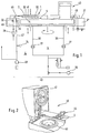
- FIG. 2 shows a perspective view of an upper part of a sputtering system 40, to which a gripper arm 44 rotatably rotated by 180 ° belongs, by means of which the substrates or compact disks (CD) designated in FIG. 2 of a device 1 for gripping substrates (disk receiver).
- the substrates reach a process station 43 via this device 1 also includes a cathode 41 shown in FIG. 2 in an open position.
- the substrate 2 is placed on a further device for gripping substrates by means of the gripper arm 44 and an associated plate 33, which also includes a gripping device (not shown in FIG. 1).
- the plate 33 is located above a plate or substrate receiving part 14.
- the two plates 33 and 14 are aligned coaxially with one another, so that the substrate 2 can be fed from the plate 33 to the substrate receiving part 14.
- the plate 14 In the position according to FIG. 1, the plate 14 has been moved upwards and seals an annular volume or an insertion chamber 30.
- the insertion chamber 30 is located between the upper plate 33 and the lower plate or substrate receiving part 14.
- the gripping elements provided on the plate 33 and not shown in FIG. 1 hold the compact disk above the substrate receiving part 14.
- the insertion chamber 30 can be flooded via a filter 28, which for this purpose is connected via a line 45 to a valve 32, which is connected to the insertion chamber 30 via a further line 46.
- a valve 32 By opening the valve 32, the lock chamber 30 is flooded.
- the upper plate is raised so that the substrate 2 can be replaced.
- the gripper arm 44 By means of the gripper arm 44, the coated compact disk can be fed to a further transport device, not shown.
- a new compact disk 2 to be processed is inserted into the feed chamber 30.
- an O-ring presses against the surface of a housing 37 of the insertion chamber 30, which is thereby closed in a vacuum-tight manner.
- the atmospheric pressure prevailing in the lock-in chamber 30 is evacuated by closing the valve 32 and then by subsequently opening a valve 26 which is connected to the lock-in chamber 30 via the line 46.
- a vacuum pump 48 pumps out the air present in the lock chamber 30 and generates the required vacuum pressure.
- grippers 3 explained in more detail below, which are shown in detail in FIG. 3, open.
- the grippers 3 grip the substrate 2 or the compact disk. This occurs immediately when the pressure in the insertion chamber 30 corresponds approximately to the pressure in a vacuum chamber 4 (FIG. 3), i.e. H. when pressure equalization has taken place. If the sluice chamber 30 has been evacuated to such an extent that the required measuring pressure, which is determined by means of a measuring cell 34, is produced, the device 1 can be lowered and the substrate 2 deposited on a turntable 49 (FIG. 1) by means of the turntable 49 of the process station 43 are fed gradually. For this purpose, the turntable 49 rotates further by 120 °.
- the substrate receiving part 14 is raised, an O-ring (not shown) resting against the underside of the cover of the cathode 41.
- the lock chamber 30 can be flooded again via the valve 32.
- the grippers 3 are pivoted again and the substrate 2 is released.
- the gripper of the substrate receiving part or the plate 33 is activated at the same time, so that the substrate can be taken over by the plate 33. This work process is repeated continuously.
- the vacuum chamber 4 is evacuated via the lines 38, 39 and the backing pump 29.
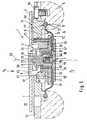
- FIG. 3 shows the device 1 for gripping and holding the substrates 2 in detail, the device 1 being only indicated schematically.
- the device 1 consists of a flange 14 ', which is detachably connected to a substrate holder 5 via screw bolts 50. Between the flange 14 'and the substrate holder 5, a semicircular groove 17 is provided, in which a bead-like edge 13 of a membrane 7 is clamped.
- the membrane 7 is located in the vacuum chamber 4 and consists of a flexible part 11 and a non-flexible part 11 'connected to it, which is designed as a circular plate and which is let into an opening 12 in the membrane 7.
- the plate 11 ' has a cylindrical projection 51, so that an edge part 52 is formed, to which the flexible part 11 of the membrane 7 can be attached or vulcanized.
- the membrane 7 seals the upper part of a vacuum chamber 4 '(FIG. 3) or 4''(FIG. 1) against the vacuum chamber 4 which is exposed to a permanent vacuum pressure P v .
- the flexible part 11 of the membrane 7 is connected with its outer edge 13 to a flange 14 'and with its inner edge 15 to the cylindrical extension 51.
- the outer edge 13 is clamped in a groove 17, 17 'of the flange 14' and the substrate holder 5.
- the vacuum chamber 4 ', 4'' is then exposed to an atmospheric pressure P a when, as already mentioned, the valve 32 is opened and the sluice chamber 30 is flooded.
- the plate 11 'of the membrane 7 has a pin 19 which is aligned coaxially with a central axis 53 of the device 1.
- the pin 19 is fixed or integrally connected to the plate 11 '.
- the pin 19 has an external thread 54 and can therefore be connected or detachably screwed to a cylindrical part 18.
- the cylindrical part 18 is also aligned coaxially to the flange 14 ′ and has a cylindrical bore 55 in its upper region, into which a pin 20 extends.
- the pin 20 is connected to a cylindrical projection 56 which is connected to the flange 14 'via connecting elements 25.
- the compact disk or the substrate 2 can be pushed onto the cylindrical extension 56 and held by means of the three or more grippers 3.
- Of the cylindrical part 18 is vertically adjustable with respect to the central axis 53 on the pin 20 when pressure difference P d occurs .
- an adjusting part or a bell-shaped flange 8 is provided at the upper end of the cylindrical part 18.
- the actuating part 8 is firmly connected to an upper end 21 of the cylindrical part 18.
- the flange 8 bears with its outer end against a lever arm 57 of one gripper 3 each.
- the gripper 3 is pivotally mounted on a bolt 31 which runs horizontally with reference to FIG. 3 between the position shown in solid lines (holding position) and a position shown in broken lines (release position).
- the lower end of the cylindrical part 18 moves with its one end or its plate 11 'in the direction of the underside of a fixed flange 22, while its other end or its adjusting part 8 bears against the gripper 3 or its lever arm 57.
- the gripper 3 is in the holding position shown in FIG. 3, in which the substrate 2 is carried by the grippers 3.
- the flange 22 is fixedly connected to a support part 24 and the flange 14 'via the connecting elements 25.
- the cylindrical spring 6 surrounds the cylindrical part 18.
- the supporting part 24 connected to the flange 22 serves to pivotably accommodate the grippers 3.
- the flange 22 has a bore 47 through which the cylindrical part 18 extends.
- the fixed flange 22 and the support part 24 are detachably connected to the flange 14 'of the device 1 via the same connecting elements 25.
- the vacuum chamber 4 ′, 4 ′′ or the sluice chamber 30 provided above the membrane 7 can, as already explained with reference to FIG. 1, be flooded via the valve 32 and evacuated via the pump 48.
- the vacuum chamber 4 provided below the membrane 7 is not flooded during work and is evacuated via a vacuum pump 27 or the backing pump or kept at a certain pressure level.
- the gripper system works completely trouble-free and can respond in a very short time, i.e. in milliseconds.
- the top of the membrane is connected to the vacuum chamber 4 'via the bore 47.
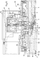
- FIGS. 4, 6 show a first device 130 for gripping and holding the substrates 2, which includes the grippers 75 which can be pivoted about an axis 83 which runs horizontally with reference to FIG. 4.
- the grippers 75 are arranged in a cylindrical housing 78 which serves to receive an electromagnet 67 which can be connected via a plug 111 to a power supply device (not shown in the drawing) (cf. FIG. 6).
- the electromagnet 67 is secured by means of a locking ring 66, which is provided at the upper end of the housing 78.
- the housing has a bottom 82 with at least three openings 74 through which the grippers 75 extend.
- the grippers 75 can be pivoted via elastically designed bearings 84 about the axis 83, which runs horizontally with reference to FIG. 4, between two stops 77, 77 'which are firmly connected to the housing 78.
- each gripper 75 has a cylindrical housing 81 for receiving an upper and a lower magnet 79 and 80.
- the wall of the cylindrical housing 81 is thin-walled and can have a wall thickness between 0.2 mm and 1.0 mm or between 0.3 mm and 0.7 mm or between 0.4 mm and 0.6 mm, in particular 0 , 5 mm, in order to ensure a good holding force on the magnet 67 when in contact.
- the upper magnet is denoted by N and the lower magnet by S.
- the gripper 75 can be adjusted and placed between the two stops 77 and 77 ' thereby the path, which is characterized by the angle ⁇ , back.
- the longitudinal central axis of the gripper 75 runs parallel to the longitudinal central axis of the housing 78.
- the substrate is secured via groove-shaped depressions 72 provided at the lower end of the gripper.
- the lower ends of the grippers extend through slot openings 92, which ensure exact guiding of the grippers. If, with reference to FIG. 4, the gripper 75 is pivoted by corresponding polarities of the ring magnet 67, it moves from the left stop 77 'to the right stop 77 and thereby assumes an inclined position, so that it recesses itself with its recess 72 moved away from the edge area of the bore or opening 12 of the substrate 2 and releases it for the transfer of the second device 1.
- the elastically designed bearing 84 can be accommodated in a corresponding annular groove 86 provided in the base 82 and in an adjoining receiving part 71.
- the receiving part 71 is detachably connected to the bottom 82 of the housing 78 by means of screws 87.
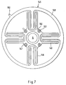
- the individual grippers 75 of the first device 130 are each offset by 120 ° to one another and in this way form gaps 148 which offer sufficient space for the grippers 3 of the second device 1 for gripping substrates. Due to the advantageously arranged spaces 148, the two devices 1 and 130 can be brought very close to one another and thus an exact transfer of the substrates between the two devices can be ensured, with the upper grippers 75 briefly engaging in the intermediate spaces 148 of the two adjacent, lower grippers 3 when the two devices are moved together during the transfer.
- the angle ⁇ between two grippers 75 lying next to one another is 120 °.
- the grippers 75 and the grippers 3 are each arranged in a star shape, and the angle between the gripper 75 and the gripper 3 is 60 °.
- FIG. 6 The device shown in FIG. 4 for gripping and holding the substrates 2 is illustrated in FIG. 6 in the overall device, the device 130 being shown as the upper device.
- a lock cover 103 is detachably connected to the stop cover 108 by means of the screw bolts 123.
- the substrate receiving part 73 with the lock cover 103 forms the upper device 130 for receiving and gripping the substrates 2. If the substrate 2 is moved over the entire device 130 to the second device 1 already described in detail in FIG.
- the lock cover 103 is placed by means of a Seal 104 seals against the end face of a recipient lid 102, 41.
- the lock-in chamber 30 is formed between the surface of the substrate holder 5 and the underside of the lock cover 103, via the line 46 can either be flooded or evacuated, as can be seen from the schematic illustration in FIG. 1.
- a spring-elastic connecting element or membrane part 145 which permits a stroke and which is equipped as a circular disk with an outer edge 149, which is formed by meandering webs 146 is connected to a centrally arranged flange 150.
- the flange 150 is connected to the substrate holder 5 via screw bolts 151, while the outer ring 149 is connected to the turntable 101.
- a pin 152 ensures the correct installation of the substrate holder 5 in the turntable 101 and locks the substrate holder 5 with respect to the turntable 101.
- the membrane 145 creates a rotation lock between these two parts, which ensures that when the substrate holder 5 is raised, the grippers 75 can engage in the spaces between the grippers 3.
- valve 26 is opened and the lock chamber 30 is evacuated via the pump 48. This creates equal pressure on the top and bottom of the substrate holder 5.
- the membrane 7 assumes the position shown in FIG. 3, with the spring 6 pivots the lever or the gripper 3 outward, holding the substrate 2 fed to it.
- the magnet 67 is actuated at the same time and pivots the grippers 75 into an inclined position according to FIG. 4 (see angle ⁇ ), the upper ends of the grippers coming into contact with the corresponding stops 77 and thereby releasing the substrate 2.
- a support plate 100 with the substrate holder 5 can now be moved into the right, lower position shown in FIG. 6, the plate or substrate holder 5 being simultaneously carried down over the membrane or the connecting element 145 until the substrate holder 5 hits a stop 140 of the turntable 101 is present.
- the substrate holder 5 can now perform a pivoting movement without a relative movement occurring between the substrate holder 5 and the turntable 101.
- the next substrate holder assumes the position described above, for which purpose the support plate 100 with the substrate holder 5 is moved up again until it bears against a seal 121 and the lock chamber 30 is closed.
- the substrate remains in the grippers 3 until the valve 32 is opened and the lock chamber is flooded, so that atmospheric pressure then occurs in the lock chamber.
- the grippers 75 of the upper device 130 can also be controlled via the pole shoes, so that they are pivoted from their inclined position into their vertical position according to FIG. 4 and thereby grasp the substrate 2. Now the upper substrate can be lifted off and the next substrate 2 can be brought into the described position by pivoting the gripper carrier 117.
Landscapes
- Chemical & Material Sciences (AREA)
- Engineering & Computer Science (AREA)
- Physics & Mathematics (AREA)
- Plasma & Fusion (AREA)
- Analytical Chemistry (AREA)
- Chemical Kinetics & Catalysis (AREA)
- Materials Engineering (AREA)
- Mechanical Engineering (AREA)
- Metallurgy (AREA)
- Organic Chemistry (AREA)
- Physical Vapour Deposition (AREA)
Applications Claiming Priority (2)
| Application Number | Priority Date | Filing Date | Title |
|---|---|---|---|
| DE19605599 | 1996-02-15 | ||
| DE19605599A DE19605599C1 (de) | 1996-02-15 | 1996-02-15 | Vorrichtung zum Transport von Substraten |
Publications (2)
| Publication Number | Publication Date |
|---|---|
| EP0790330A1 true EP0790330A1 (fr) | 1997-08-20 |
| EP0790330B1 EP0790330B1 (fr) | 2000-05-31 |
Family
ID=7785483
Family Applications (1)
| Application Number | Title | Priority Date | Filing Date |
|---|---|---|---|
| EP97101694A Expired - Lifetime EP0790330B1 (fr) | 1996-02-15 | 1997-02-04 | Dispositif de transport de substrats |
Country Status (4)
| Country | Link |
|---|---|
| US (1) | US5879121A (fr) |
| EP (1) | EP0790330B1 (fr) |
| JP (1) | JP4040132B2 (fr) |
| DE (2) | DE19605599C1 (fr) |
Cited By (2)
| Publication number | Priority date | Publication date | Assignee | Title |
|---|---|---|---|---|
| EP1029942A1 (fr) * | 1998-08-19 | 2000-08-23 | Shibaura Mechatronics Corporation | Dispositif a depression et mecanisme d'entrainement a cet effet |
| EP0801147B1 (fr) * | 1996-04-13 | 2002-01-16 | Singulus Technologies AG | Dispositif de transport de substrats |
Families Citing this family (9)
| Publication number | Priority date | Publication date | Assignee | Title |
|---|---|---|---|---|
| DE19814834A1 (de) * | 1998-04-02 | 1999-10-07 | Leybold Systems Gmbh | Vorrichtung zum Greifen und Halten eines flachen Substrats |
| US6264804B1 (en) | 2000-04-12 | 2001-07-24 | Ske Technology Corp. | System and method for handling and masking a substrate in a sputter deposition system |
| US6413381B1 (en) | 2000-04-12 | 2002-07-02 | Steag Hamatech Ag | Horizontal sputtering system |
| DE10050412B4 (de) * | 2000-10-12 | 2004-12-09 | Pfeiffer Vacuum Systems Gmbh | Vorrichtung zum Greifen und Halten von auf einem Substrathalter abgelegten Disketten |
| US6596083B2 (en) * | 2001-03-16 | 2003-07-22 | Toda Citron Technology, Inc. | Disk lubrication mechanism |
| DE10236456A1 (de) * | 2002-08-08 | 2004-02-26 | Steag Hamatech Ag | Haltevorrichtung für Substrate in einer Vakuumkammer |
| US7978583B2 (en) * | 2005-05-24 | 2011-07-12 | Cinram International Inc. | Apparatus and method for forming reflective layer of optical disc |
| US20140020583A1 (en) * | 2012-07-17 | 2014-01-23 | Avi Barazani | Adaptable impression drum |
| CN115216749A (zh) * | 2021-04-16 | 2022-10-21 | 上海新微技术研发中心有限公司 | 一种基片处理系统及其控制方法 |
Citations (1)
| Publication number | Priority date | Publication date | Assignee | Title |
|---|---|---|---|---|
| DE9307263U1 (fr) * | 1993-05-13 | 1993-07-22 | Leybold Ag, 63450 Hanau, De |
Family Cites Families (12)
| Publication number | Priority date | Publication date | Assignee | Title |
|---|---|---|---|---|
| FR1350846A (fr) * | 1962-12-20 | 1964-01-31 | Alsacienne Atom | Grappin électrique à cartouches |
| US4199183A (en) * | 1978-06-12 | 1980-04-22 | Industrial Automation Corp. | Internal gripper apparatus having positive container alignment |
| US4676710A (en) * | 1983-12-01 | 1987-06-30 | Fuji Photo Film Co., Ltd. | Apparatus for positioning disc-shaped film unit |
| DE3716498C2 (de) * | 1987-05-16 | 1994-08-04 | Leybold Ag | Vorrichtung zum Ein- und Ausschleusen von Werkstücken in eine Beschichtungskammer |
| DE3808644C1 (fr) * | 1988-03-15 | 1989-07-13 | Deutsche Gesellschaft Fuer Wiederaufarbeitung Von Kernbrennstoffen Mbh, 3000 Hannover, De | |
| DE4110490C2 (de) * | 1991-03-30 | 2002-02-28 | Unaxis Deutschland Holding | Kathodenzerstäubungsanlage |
| DE4340522A1 (de) * | 1993-11-29 | 1995-06-01 | Leybold Ag | Vorrichtung und Verfahren zum schrittweisen und automatischen Be- und Entladen einer Beschichtungsanlage |
| US5698030A (en) * | 1995-01-31 | 1997-12-16 | Nobler Technologies, Inc. | Compact disc coating and handling system |
| US5637200A (en) * | 1995-02-08 | 1997-06-10 | Nobler Technologies, Inc. | Compact disk locking apparatus |
| KR0146216B1 (ko) * | 1995-04-24 | 1998-11-02 | 정문술 | 반도체 소자검사기의 소자로딩,언로딩장치 |
| DE19529537A1 (de) * | 1995-08-11 | 1997-02-13 | Leybold Ag | Vorrichtung zum Greifen und Halten eines flachen Substrats |
| DE19529945C2 (de) * | 1995-08-16 | 1997-12-11 | Leybold Ag | Vorrichtung zum Greifen und Halten eines flachen Substrats |
-
1996
- 1996-02-15 DE DE19605599A patent/DE19605599C1/de not_active Expired - Fee Related
-
1997
- 1997-02-04 EP EP97101694A patent/EP0790330B1/fr not_active Expired - Lifetime
- 1997-02-04 DE DE59701790T patent/DE59701790D1/de not_active Expired - Lifetime
- 1997-02-17 JP JP03228497A patent/JP4040132B2/ja not_active Expired - Fee Related
- 1997-02-18 US US08/802,792 patent/US5879121A/en not_active Expired - Fee Related
Patent Citations (1)
| Publication number | Priority date | Publication date | Assignee | Title |
|---|---|---|---|---|
| DE9307263U1 (fr) * | 1993-05-13 | 1993-07-22 | Leybold Ag, 63450 Hanau, De |
Cited By (3)
| Publication number | Priority date | Publication date | Assignee | Title |
|---|---|---|---|---|
| EP0801147B1 (fr) * | 1996-04-13 | 2002-01-16 | Singulus Technologies AG | Dispositif de transport de substrats |
| EP1029942A1 (fr) * | 1998-08-19 | 2000-08-23 | Shibaura Mechatronics Corporation | Dispositif a depression et mecanisme d'entrainement a cet effet |
| EP1029942A4 (fr) * | 1998-08-19 | 2004-11-10 | Shibaura Mechatronics Corp | Dispositif a depression et mecanisme d'entrainement a cet effet |
Also Published As
| Publication number | Publication date |
|---|---|
| US5879121A (en) | 1999-03-09 |
| DE19605599C1 (de) | 1996-10-31 |
| EP0790330B1 (fr) | 2000-05-31 |
| JP4040132B2 (ja) | 2008-01-30 |
| JPH09228044A (ja) | 1997-09-02 |
| DE59701790D1 (de) | 2000-07-06 |
Similar Documents
| Publication | Publication Date | Title |
|---|---|---|
| EP0801147A1 (fr) | Dispositif de transport de substrats | |
| EP0790331B1 (fr) | Dispositif de maintien et de préhension de substrats | |
| EP0790330B1 (fr) | Dispositif de transport de substrats | |
| EP2355132B1 (fr) | Soupape de transfert à clapets dotée de barres de fermeture de soupape pivotantes | |
| DE3204312A1 (de) | Einschleusvorrichtung | |
| EP1753990B1 (fr) | Dispositif de blocage | |
| DE3630035C2 (de) | Vorrichtung zum Einladen eines Halbleiterwafers in eine Behandlungskammer und Ionenimplantationsvorrichtung mit dieser Vorrichtung | |
| EP2422362A1 (fr) | Dispositif de transport à cadre d'étanchéité pouvant subir un fléchissement | |
| EP0389820B1 (fr) | Dispositif pour faire entrer ou sortir par une écluse une pièce dans une chambre à vide | |
| DE3912296C2 (de) | Vorrichtung zur Aufnahme und Halterung von Substraten | |
| DE102006043813B4 (de) | Schieberventil für eine Beschichtungsanlage und Beschichtungsanlage | |
| DE4427984A1 (de) | Vorrichtung zum Ein- und Ausschleusen von Werkstücken in eine Beschichtungskammer | |
| DE10050412B4 (de) | Vorrichtung zum Greifen und Halten von auf einem Substrathalter abgelegten Disketten | |
| DE102017104333B3 (de) | Zentrieranordnung, Ventilanordnung, Vakuumanordnung und Verfahren | |
| DE10355678B4 (de) | Vakuumsystem, Verfahren zum Transport eines Objekts im Vakuum mittels des Vakuumsystems und Verwendung des Vakuumsystems | |
| DE102019124484A1 (de) | Ventilanordnung, Vakuumanordnung und Verfahren | |
| EP1194928A1 (fr) | Dispositif et procede de fabrication d'un support de donnees | |
| DE102011082900B4 (de) | Substratbehandlungsanlage mit austauschbarem Rohrtarget und Rohrtarget-Hebezeug dazu | |
| EP0679477A2 (fr) | Dispositif pour la mise en place de rondelles de couverture | |
| DE954006C (de) | Steuereinrichtung fuer eine schnellschliessende Druckluftbremse insbesondere fuer Schachtfoerdermaschinen und Aufzuege | |
| DE102010016325A1 (de) | Substratwendeeinrichtung | |
| DE2951387A1 (de) | Schnellschlussklappenventil fuer hochvakuum- oder ultrahoch-vakuumbetriebe | |
| DE2229384B2 (de) | Schleuse zum Einfuhren einer Sonde in ein Vakuum System | |
| DE19625598A1 (de) | Sputtervorrichtung und Verfahren zum Austauschen einer Innenkammer derselben | |
| EP0801143A1 (fr) | Appareil de recouvrement ou masquage de substrats |
Legal Events
| Date | Code | Title | Description |
|---|---|---|---|
| PUAI | Public reference made under article 153(3) epc to a published international application that has entered the european phase |
Free format text: ORIGINAL CODE: 0009012 |
|
| AK | Designated contracting states |
Kind code of ref document: A1 Designated state(s): CH DE FR GB LI NL SE |
|
| 17P | Request for examination filed |
Effective date: 19980113 |
|
| RAP1 | Party data changed (applicant data changed or rights of an application transferred) |
Owner name: SINGULUS TECHNOLOGIES AG |
|
| GRAG | Despatch of communication of intention to grant |
Free format text: ORIGINAL CODE: EPIDOS AGRA |
|
| 17Q | First examination report despatched |
Effective date: 19990115 |
|
| GRAG | Despatch of communication of intention to grant |
Free format text: ORIGINAL CODE: EPIDOS AGRA |
|
| GRAH | Despatch of communication of intention to grant a patent |
Free format text: ORIGINAL CODE: EPIDOS IGRA |
|
| GRAH | Despatch of communication of intention to grant a patent |
Free format text: ORIGINAL CODE: EPIDOS IGRA |
|
| GRAA | (expected) grant |
Free format text: ORIGINAL CODE: 0009210 |
|
| AK | Designated contracting states |
Kind code of ref document: B1 Designated state(s): CH DE FR GB LI NL SE |
|
| REG | Reference to a national code |
Ref country code: CH Ref legal event code: EP |
|
| REG | Reference to a national code |
Ref country code: CH Ref legal event code: NV Representative=s name: E. BLUM & CO. PATENTANWAELTE |
|
| REF | Corresponds to: |
Ref document number: 59701790 Country of ref document: DE Date of ref document: 20000706 |
|
| GBT | Gb: translation of ep patent filed (gb section 77(6)(a)/1977) |
Effective date: 20000731 |
|
| ET | Fr: translation filed | ||
| PLBE | No opposition filed within time limit |
Free format text: ORIGINAL CODE: 0009261 |
|
| STAA | Information on the status of an ep patent application or granted ep patent |
Free format text: STATUS: NO OPPOSITION FILED WITHIN TIME LIMIT |
|
| 26N | No opposition filed | ||
| REG | Reference to a national code |
Ref country code: GB Ref legal event code: IF02 |
|
| PGFP | Annual fee paid to national office [announced via postgrant information from national office to epo] |
Ref country code: SE Payment date: 20020221 Year of fee payment: 6 |
|
| PG25 | Lapsed in a contracting state [announced via postgrant information from national office to epo] |
Ref country code: SE Free format text: LAPSE BECAUSE OF NON-PAYMENT OF DUE FEES Effective date: 20030205 |
|
| EUG | Se: european patent has lapsed | ||
| REG | Reference to a national code |
Ref country code: CH Ref legal event code: PFA Owner name: SINGULUS TECHNOLOGIES AG Free format text: SINGULUS TECHNOLOGIES AG#JUNKERSSTRASSE 1#63755 ALZENAU (DE) -TRANSFER TO- SINGULUS TECHNOLOGIES AG#JUNKERSSTRASSE 1#63755 ALZENAU (DE) |
|
| PGFP | Annual fee paid to national office [announced via postgrant information from national office to epo] |
Ref country code: NL Payment date: 20090226 Year of fee payment: 13 |
|
| PGFP | Annual fee paid to national office [announced via postgrant information from national office to epo] |
Ref country code: GB Payment date: 20090223 Year of fee payment: 13 |
|
| REG | Reference to a national code |
Ref country code: NL Ref legal event code: V1 Effective date: 20100901 |
|
| GBPC | Gb: european patent ceased through non-payment of renewal fee |
Effective date: 20100204 |
|
| PG25 | Lapsed in a contracting state [announced via postgrant information from national office to epo] |
Ref country code: NL Free format text: LAPSE BECAUSE OF NON-PAYMENT OF DUE FEES Effective date: 20100901 |
|
| PG25 | Lapsed in a contracting state [announced via postgrant information from national office to epo] |
Ref country code: GB Free format text: LAPSE BECAUSE OF NON-PAYMENT OF DUE FEES Effective date: 20100204 |
|
| PGFP | Annual fee paid to national office [announced via postgrant information from national office to epo] |
Ref country code: FR Payment date: 20110307 Year of fee payment: 15 |
|
| PGFP | Annual fee paid to national office [announced via postgrant information from national office to epo] |
Ref country code: CH Payment date: 20120229 Year of fee payment: 16 |
|
| REG | Reference to a national code |
Ref country code: FR Ref legal event code: ST Effective date: 20121031 |
|
| PG25 | Lapsed in a contracting state [announced via postgrant information from national office to epo] |
Ref country code: FR Free format text: LAPSE BECAUSE OF NON-PAYMENT OF DUE FEES Effective date: 20120229 |
|
| REG | Reference to a national code |
Ref country code: CH Ref legal event code: PL |
|
| PG25 | Lapsed in a contracting state [announced via postgrant information from national office to epo] |
Ref country code: CH Free format text: LAPSE BECAUSE OF NON-PAYMENT OF DUE FEES Effective date: 20130228 Ref country code: LI Free format text: LAPSE BECAUSE OF NON-PAYMENT OF DUE FEES Effective date: 20130228 |
|
| PGFP | Annual fee paid to national office [announced via postgrant information from national office to epo] |
Ref country code: DE Payment date: 20140226 Year of fee payment: 18 |
|
| REG | Reference to a national code |
Ref country code: DE Ref legal event code: R119 Ref document number: 59701790 Country of ref document: DE |
|
| PG25 | Lapsed in a contracting state [announced via postgrant information from national office to epo] |
Ref country code: DE Free format text: LAPSE BECAUSE OF NON-PAYMENT OF DUE FEES Effective date: 20150901 |