EP0790206B1 - Procédé et dispositif de changement automatique de piles - Google Patents
Procédé et dispositif de changement automatique de piles Download PDFInfo
- Publication number
- EP0790206B1 EP0790206B1 EP97101402A EP97101402A EP0790206B1 EP 0790206 B1 EP0790206 B1 EP 0790206B1 EP 97101402 A EP97101402 A EP 97101402A EP 97101402 A EP97101402 A EP 97101402A EP 0790206 B1 EP0790206 B1 EP 0790206B1
- Authority
- EP
- European Patent Office
- Prior art keywords
- pile
- sheet
- auxiliary
- region
- carriers
- Prior art date
- Legal status (The legal status is an assumption and is not a legal conclusion. Google has not performed a legal analysis and makes no representation as to the accuracy of the status listed.)
- Expired - Lifetime
Links
Images


Classifications
-
- B—PERFORMING OPERATIONS; TRANSPORTING
- B65—CONVEYING; PACKING; STORING; HANDLING THIN OR FILAMENTARY MATERIAL
- B65H—HANDLING THIN OR FILAMENTARY MATERIAL, e.g. SHEETS, WEBS, CABLES
- B65H31/00—Pile receivers
- B65H31/30—Arrangements for removing completed piles
- B65H31/3009—Arrangements for removing completed piles by dropping, e.g. removing the pile support from under the pile
- B65H31/3018—Arrangements for removing completed piles by dropping, e.g. removing the pile support from under the pile from opposite part-support elements, e.g. operated simultaneously
-
- B—PERFORMING OPERATIONS; TRANSPORTING
- B65—CONVEYING; PACKING; STORING; HANDLING THIN OR FILAMENTARY MATERIAL
- B65H—HANDLING THIN OR FILAMENTARY MATERIAL, e.g. SHEETS, WEBS, CABLES
- B65H31/00—Pile receivers
- B65H31/32—Auxiliary devices for receiving articles during removal of a completed pile
-
- B—PERFORMING OPERATIONS; TRANSPORTING
- B65—CONVEYING; PACKING; STORING; HANDLING THIN OR FILAMENTARY MATERIAL
- B65H—HANDLING THIN OR FILAMENTARY MATERIAL, e.g. SHEETS, WEBS, CABLES
- B65H43/00—Use of control, checking, or safety devices, e.g. automatic devices comprising an element for sensing a variable
- B65H43/06—Use of control, checking, or safety devices, e.g. automatic devices comprising an element for sensing a variable detecting, or responding to, completion of pile
-
- B—PERFORMING OPERATIONS; TRANSPORTING
- B65—CONVEYING; PACKING; STORING; HANDLING THIN OR FILAMENTARY MATERIAL
- B65H—HANDLING THIN OR FILAMENTARY MATERIAL, e.g. SHEETS, WEBS, CABLES
- B65H2220/00—Function indicators
- B65H2220/09—Function indicators indicating that several of an entity are present
-
- B—PERFORMING OPERATIONS; TRANSPORTING
- B65—CONVEYING; PACKING; STORING; HANDLING THIN OR FILAMENTARY MATERIAL
- B65H—HANDLING THIN OR FILAMENTARY MATERIAL, e.g. SHEETS, WEBS, CABLES
- B65H2301/00—Handling processes for sheets or webs
- B65H2301/40—Type of handling process
- B65H2301/42—Piling, depiling, handling piles
- B65H2301/422—Handling piles, sets or stacks of articles
- B65H2301/4226—Delivering, advancing piles
- B65H2301/42261—Delivering, advancing piles by dropping
- B65H2301/422615—Delivering, advancing piles by dropping from opposite part-support elements, e.g. operated simultaneously
-
- B—PERFORMING OPERATIONS; TRANSPORTING
- B65—CONVEYING; PACKING; STORING; HANDLING THIN OR FILAMENTARY MATERIAL
- B65H—HANDLING THIN OR FILAMENTARY MATERIAL, e.g. SHEETS, WEBS, CABLES
- B65H2301/00—Handling processes for sheets or webs
- B65H2301/40—Type of handling process
- B65H2301/42—Piling, depiling, handling piles
- B65H2301/426—Forming batches
- B65H2301/4262—Forming batches by inserting auxiliary support as defined in B65H31/32
- B65H2301/42622—Forming batches by inserting auxiliary support as defined in B65H31/32 and using auxiliary means for facilitating introduction of the auxiliary support
-
- B—PERFORMING OPERATIONS; TRANSPORTING
- B65—CONVEYING; PACKING; STORING; HANDLING THIN OR FILAMENTARY MATERIAL
- B65H—HANDLING THIN OR FILAMENTARY MATERIAL, e.g. SHEETS, WEBS, CABLES
- B65H2405/00—Parts for holding the handled material
- B65H2405/30—Other features of supports for sheets
- B65H2405/32—Supports for sheets partially insertable - extractable, e.g. upon sliding movement, drawer
-
- B—PERFORMING OPERATIONS; TRANSPORTING
- B65—CONVEYING; PACKING; STORING; HANDLING THIN OR FILAMENTARY MATERIAL
- B65H—HANDLING THIN OR FILAMENTARY MATERIAL, e.g. SHEETS, WEBS, CABLES
- B65H2801/00—Application field
- B65H2801/03—Image reproduction devices
- B65H2801/21—Industrial-size printers, e.g. rotary printing press
Definitions
- the invention relates to a method for automatic changing a boom stack according to the preamble of claim 1 and a device according to the preamble of claim 4.
- GB 2 267 275 A describes a device for removing stacks from a Stacking station described.
- the device has a stack already formed retractable sword. This is done by a circulating belt within the stack and created a gap above the sword. The device therefore engages in the already finished batch. A separation and interim stacking of free falling sheets for transfer to a stack pallet is not described.
- the aim of the invention is to change a stack of sheets on one Improve sheet delivery.
- the object of the invention is the procedure of changing the stack on one To improve the sheet delivery so that the process is both safer as well as for a larger area regarding the quality of substrates is applicable.
- the task is characterized by the characteristics the method claim 1 and the device claim 4 solved.
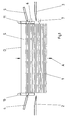
- Fig. 1 is a stack changing device on a sheet delivery Sheet printing machine with those required for a so-called non-stop operation Facilities shown.
- the sheet delivery is only partially shown here an endless chain conveyor system, also not shown, and a Main stacker provided so that printed sheets D from the printing units of Sheet printing machine conveyed to the sheet delivery, above a stacking area S can be released and filed.
- the printed sheets D are braked and placed freely on a sheet stack 1.
- the sheet stack 1 sits on a pallet, which in turn is carried by a main stacking hoist.
- the main stacking hoist ensures a continuous lowering of the pallet when increasing the sheet stack 1 through the supplied and deposited printed sheets D.
- the auxiliary stacking device On both sides of the area of the sheet stack 1 is an auxiliary stacking device at the level of the stacking area S. arranged.
- the auxiliary stacking device consists of two mirror images Arch wings 2, 3, i.e. from the transverse sides perpendicular to one of the Sheet printing machine predetermined sheet running direction arranged on the sheet delivery are.
- the sheet supporting surfaces 2, 3 are each in the stacking area with the aid of a drive S and movable out of it.
- the arch wings 2, 3 and thus also assigned to the stacking area S on both sides of the sheet stack 1 two sheet separators 4, 5 arranged. They consist of small ones Pneumatic cylinders, on the working cylinders of which pins are arranged, which in the Stacking area S are retractable.
- the sheet separating devices 4, 5 are in their Orientation to the position of the incoming printed sheets D slightly inclined so that when the sheet separating devices 4, 5 are retracted, a support surface that is curved downward for the incoming printed sheets D. Furthermore, with the sheet delivery Control devices connected to the sequence of movements described Sheet separators 2, 3, sheet wings 4, 5 and main stacker control each other.
- the sheet separators 4, 5 are in the area of side guides 10, 11 arranged, which serve an exact stack formation of the sheet stack 1. For quick and Gentle handling of the printed sheets D when changing stacks is therefore the following procedure intended:
- Fig. 1 the initial state of the sheet stack 1 is shown in the sheet delivery.
- the Sheet stack 1 is filled almost up to its maximum stack height, the sheet supporting surfaces 2, 3 are on hold and sheet separators 4, 5 are on hold.
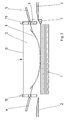
- a start signal is given at Reaching a certain height H1 of the sheet stack 1, e.g. from the position of the Main stacking device can be derived.
- the start signal causes the sheet stack 1 is lowered in direction A. The lowering movement takes place with a relatively slow Lowering speed V1 in order not to disturb the stack formation too much.
- Sheet separating devices 4, 5 shot into the area of the falling printing sheets D.
- This process is controlled with respect to the functions of the printing press so that the Time at which the sheet separating device 4, 5 was shot into the area of a gap must fall between the falling printed sheets D.
- This control process is for example to match the movement of the chain conveyor system or can be derived from this become.
- the Lowering speed increased to V2 to match the top of the sheet stack 1 to get faster into the area of the arch wings 2, 3.
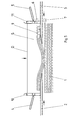
- FIG. 3 shows the third step of the batch change process. It is shown that two printed sheets D are now deposited on the sheet separating devices 4, 5 to have. They lie in an arc with their central part on the surface of the sheet stack 1 on. In the meantime, the movement to lower the main stack is when a second one is reached Sensor 7 has been stopped at a height H2. The position corresponding to the height is H2 also derivable and approachable from the movement of the main stacking hoist, so that one Device in the drive of the main stacker can serve as a sensor. To this Defined point in time is the retracting movement of the arch wings 2, 3 in the direction started for sheet stack 1. This causes the two arch wings 2, 3 in the stacking area S above the sheet stack 1 from the side edges move in. Through the arranged above the arch wings 2, 3 Side guides 10, 11, the falling printed sheets D are also on the Sheet separators 4, 5 still well aligned.
- the method is supplemented by a corresponding control of the known Device for managing the batch change.
- the arrangement of the elements is over Figures 1 to 6 can be seen.
- the assignment of the movements between the Sheet separation devices 4, 5 and the sheet wings 2, 3 and the movement of the Main stacking hoist is via sensors 6, 7, 8 in the area of the upper edge of the Sheet stack 1 and controlled in the area of the sheet wings 2, 3.
- First is a Sensor 6 provided that detect the surface or top edge of the sheet stack 1 and the shooting-in movement of the sheet separating devices 4 in a certain position, 5 controls. This should happen when the sheet stack 1 just below the Sheet separators 4, 5 is lowered.
- Another sensor 7 is arranged at the point where the surface or upper edge of the sheet stack 1 is to have the lower position during use of the auxiliary stacking device, which was designated as height H2.
- this position H2 of the second sensor 7 the sheet stack 1 is stopped and at the same time the sheet support surfaces 2, 3 are set in motion for insertion into the area of the sheet stack 1.
- This control ensures that a quick transition to retracting the sheet support surfaces 2, 3 is achieved and at the same time only a few printed sheets D come to rest on the sheet separating devices 4, 5, with the positive effects mentioned above.
- a signal for a travel path for the main stacking hoist can also be derived, which has to be traversed after the position H1 has been reached until the downward movement has stopped. The sensor 7 would thus be seen as part of the main stacking hoist.
- a third sensor 8 is assigned to the arch wings 2, 3.
- This sensor 8 detects the retracting movement of the arch wings 2, 3.
- the sensor 8 serves the To control sheet separation devices 4, 5 and the sheet separation devices 4, 5 pull when the arch wings 2, 3 are so far below the auxiliary stack 9 are retracted so that they can accommodate it.
- When pulling the Sheet separators 4, 5 then drop the accumulated printed sheets D onto the tight standing above the sheet stack 1 sheet wings 2, 3 and are relatively flat on the sheet stack 1 and the sheet wings 2, 3. This improves it Insert the sheet support surfaces 2, 3 considerably, since the printed sheets D of the auxiliary stack 9 are only slightly arched or bent downwards and when pushed in Arch wings 2, 3 can hardly oppose resistance.
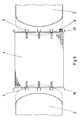
- FIG. 8 also shows a top view of the stacking area S, how the sheet support surfaces 2, 3 move relative to the sheet stack 1.
- the position recognized by the sensor 8 is shown in broken lines. there it can be seen that the sheet supporting surfaces 2, 3 already extend into the stacking area S. and so the printed sheets D can take over.
- the sensors 6, 7 and 8 with one of the side guides 10, 11th are connected.
- the sensors 6, 7, 8 are thereby set to different sheet formats always correctly positioned. This ensures that the Print sheet D or sheet stack 1 always and with any format setting safely guided and clearly recognized even when changing stacks.
Claims (9)
- Procédé pour changer des piles de feuilles (1) dans une sortie d'une machine d'impression de feuilles, comportant des supports de pile auxiliaire (2, 3) agencés dans la sortie et pouvant être introduits dans la zone d'empilage (S) de la sortie au-dessus d'une pile de feuilles (1), ainsi que des dispositifs de séparation de feuilles (4, 5) agencés au-dessus des supports de pile auxiliaire (2, 3), les dispositifs de séparation de feuilles (4, 5) pouvant être tout d'abord entrés dans la zone d'empilage (S) lorsqu'une hauteur limite de pile est atteinte et, ensuite, pendant que des feuilles d'impression (D) imprimées par la machine d'impression de feuilles sont encore déposées de façon continue dans la sortie, les supports de pile auxiliaire (2, 3) pouvant être entrés dans la zone d'empilage (S) pour former une pile auxiliaire (9) et, par la suite, après mise à disposition d'un nouveau support de pile vide (12) pour le dépôt de la pile auxiliaire (9) sur le support de pile (12), être à nouveau retirés de la zone d'empilage (S),
caractérisé en ce que :après avoir atteint la hauteur limite de pile, la pile de feuilles (1) est abaissée à une première vitesse d'abaissement,les dispositifs de séparation de feuilles (4, 5) sont entrés, pendant le mouvement d'abaissement de la pile de feuilles (1), à la première vitesse d'abaissement dans la zone d'empilage (S),après l'entrée des dispositifs de séparation de feuilles (4, 5) dans la zone d'empilage (S), la pile de feuilles (1) est abaissée à une seconde vitesse d'abaissement plus grande,le mouvement d'abaissement de la pile de feuilles (1), après avoir atteint une seconde hauteur, qui se trouve juste au-dessous du dessous des supports de pile auxiliaire (2, 3), est arrêté,directement ensuite, les supports de pile auxiliaire (2, 3) sont entrés dans la zone d'empilage (S), etalors que le mouvement d'abaissement de la pile de feuilles (1) est arrêté pendant le mouvement pour l'entrée des supports de pile auxiliaire (2, 3) dans la zone d'empilage (S), les dispositifs de séparation de feuilles (4, 5) sont retirés de la zone d'empilage (S). - Procédé selon la revendication 1,
caractérisé en ce que les dispositifs de séparation de feuilles (4, 5) sont retirés de la zone d'empilage (S) de façon dépendant de la position des supports de pile auxiliaire (2, 3) entrant dans la zone d'empilage (S). - Procédé selon la revendication 1,
caractérisé en ce que :la pile de feuilles (1) est abaissée ou soulevée par une unité de levage de pile principale,au moyen de l'unité de levage de pile principale, une palette vide (12) est soulevée jusqu'au-dessous des supports de pile auxiliaire (2, 3),la pile auxiliaire (9), alors que l'unité de levage de pile principale est arrêtée, est déposée sur la palette (12), etla nouvelle pile de feuilles (1) sur la palette (12), après la réception des supports de pile auxiliaire (2, 3), est soulevée, de façon dépendant de la position pendant le déplacement des supports de pile auxiliaire (2, 3) retirés de la zone d'empilage (S), à nouveau dans la zone d'empilage (S) entre des guides latéraux (10, 11). - Dispositif pour la mise en oeuvre du procédé pour changer des piles de feuilles (1) dans une sortie d'une machine d'impression de feuilles selon la revendication 1, comportant :caractérisé en ce que :des moyens agencés dans la sortie pour soulever et abaisser une pile de feuilles (1) ou pour la mise à disposition d'un nouveau support vide de pile (12), par exemple une unité de levage de pile principale,de plus des supports de pile auxiliaire (2, 3) pouvant être entrés dans la zone d'empilage (S) dé la sortie au-dessus de la pile de feuilles (1),ainsi que des dispositifs de séparation de feuilles (4, 5) agencés au-dessus des supports de pile auxiliaire (2, 3) et pouvant être entrés de même dans la zone d'empilage (S),des moyens pour détecter une hauteur limite de pile, etdes moyens (10, 11) pour le guidage latéral des feuilles d'impression (D) dans la zone d'empilage (S) pendant la dépose des feuilles d'impression (D) sur la pile de feuilles (1),dans la zone d'empilage (S), au moins un premier capteur (6) pour détecter le bord supérieur de la pile de feuilles (1) est agencé à une première hauteur,des moyens de mesure sont prévus, qui, dans la zone d'empilage (S), au-dessous du premier capteur (6), déterminent au moins une seconde position du bord supérieur de la pile de feuilles (1) à une seconde hauteur (H2), et les moyens de mesure comportent au moins un second capteur (7) qui, pour déterminer le bord supérieur de la pile de feuilles (1), est agencé dans une position juste au-dessous des supports de pile auxiliaire (2, 3) à la seconde hauteur (H2),au moins un troisième capteur (8) détectant la position des supports de pile auxiliaire (2, 3) lors du mouvement d'entrée ou du mouvement de sortie est prévu de façon associée aux supports de pile auxiliaire (2, 3),un dispositif de commande est prévu, de sorte que le premier capteur (6) peut être relié à la commande pour déclencher le mouvement d'entrée des dispositifs de séparation de pile (4, 5),les moyens de mesure pour déterminer la seconde position à la seconde hauteur (H2) peuvent être reliés à la commande pour déclencher le mouvement d'entrée des supports de pile auxiliaire (2, 3),le troisième capteur (8) peut être relié à la commande pour déclencher le mouvement de sortie des dispositifs de séparation de feuilles (4, 5), etles moyens pour soulever et abaisser la pile de feuilles (1), par exemple l'unité de levage de pile principale, peuvent être entraínés à une première vitesse d'abaissement et à une seconde vitesse d'abaissement plus grande.
- Dispositif selon la revendication 4,
caractérisé en ce que le premier capteur (6) est agencé au-dessous des dispositifs de séparation de feuilles (4, 5) dans la zone des guides latéraux (10, 11). - Dispositif selon la revendication 4 ou 5,
caractérisé en ce que le second capteur (7) est prévu comme un capteur détectant la position d'un mouvement d'entraínement de l'unité de levage de pile principale relativement au mouvement de levage de la pile de feuilles (1). - Dispositif selon les revendications 4 à 6,
caractérisé en ce que le troisième capteur (8) est associé à un marquage des supports de pile auxiliaire (2, 3) relativement à leur direction de déplacement. - Dispositif selon les revendications 4 à 6,
caractérisé en ce que le troisième capteur (8) est associé à une partie, en retrait dans la direction de déplacement par rapport à la pile de feuilles (1), du bord avant d'au moins un des deux supports de pile auxiliaire (2, 3). - Dispositif selon une des ou toutes les revendications 4 à 8,
caractérisé en ce qu'au moins le premier (6) et le troisième capteur (8) sont reliés à des éléments réglables au format des feuilles.
Applications Claiming Priority (2)
| Application Number | Priority Date | Filing Date | Title |
|---|---|---|---|
| DE19605322 | 1996-02-14 | ||
| DE19605322 | 1996-02-14 |
Publications (2)
| Publication Number | Publication Date |
|---|---|
| EP0790206A1 EP0790206A1 (fr) | 1997-08-20 |
| EP0790206B1 true EP0790206B1 (fr) | 2001-04-25 |
Family
ID=7785306
Family Applications (1)
| Application Number | Title | Priority Date | Filing Date |
|---|---|---|---|
| EP97101402A Expired - Lifetime EP0790206B1 (fr) | 1996-02-14 | 1997-01-30 | Procédé et dispositif de changement automatique de piles |
Country Status (5)
| Country | Link |
|---|---|
| US (1) | US5769413A (fr) |
| EP (1) | EP0790206B1 (fr) |
| JP (1) | JP2768664B2 (fr) |
| AT (1) | ATE200770T1 (fr) |
| DE (1) | DE59703408D1 (fr) |
Families Citing this family (20)
| Publication number | Priority date | Publication date | Assignee | Title |
|---|---|---|---|---|
| JPH115664A (ja) * | 1997-04-17 | 1999-01-12 | Canon Inc | 排紙スタック装置およびこれを備えた画像形成装置 |
| US6302606B1 (en) * | 1999-01-20 | 2001-10-16 | Canon Kabushiki Kaisha | Sheet receiving/stacking device, and image forming apparatus having the same |
| US6293543B1 (en) * | 1999-01-26 | 2001-09-25 | Gradco (Japan) Ltd. | Universal sheet receiver for stackers |
| DE19911524C2 (de) * | 1999-03-16 | 2002-02-14 | Roland Man Druckmasch | Vorrichtung zum Wechseln von Bogenstapeln in einem Ausleger einer Bogendruckmaschine |
| DE10056728A1 (de) | 1999-12-08 | 2001-06-13 | Heidelberger Druckmasch Ag | Vorrichtung zum Hochhalten von Bogen |
| DE10061005B4 (de) * | 1999-12-22 | 2009-11-12 | Heidelberger Druckmaschinen Ag | Trennhilfe beim Stapelwechsel an einer Druckmaschine |
| US6238114B1 (en) | 2000-03-03 | 2001-05-29 | Lexmark International, Inc. | Print media handling system and method of using same |
| US6688083B1 (en) | 2000-11-17 | 2004-02-10 | Lockheed Martin Corporation | Drop control mechanism for flat articles |
| EP1262435A1 (fr) * | 2001-06-02 | 2002-12-04 | BIELOMATIK LEUZE GmbH + Co. | Méthode et dispositif pour empiler des matières premières, en particulier des feuilles de papier ou des groupes de feuilles de papier |
| EP1424301B1 (fr) * | 2002-11-28 | 2010-04-07 | bielomatik Leuze GmbH + Co KG | Méthode et dispositif pour empiler un matériau en feuille |
| JP4227824B2 (ja) | 2003-03-28 | 2009-02-18 | 三菱重工業株式会社 | 枚葉印刷機の排紙装置 |
| CN101041239B (zh) * | 2007-04-13 | 2010-05-19 | 青岛美光机械有限公司 | 切纸机自动更换纸垫板的装置和方法 |
| EP2361865B1 (fr) * | 2010-02-19 | 2015-09-16 | Müller Martini Holding AG | Procédé et dispositif de formation de piles à partir d'un flux de produits d'impression en formation imbriquée |
| WO2013033966A1 (fr) * | 2011-09-05 | 2013-03-14 | 宁波为创办公设备有限公司 | Structure de séparation de papier automatique et structure d'alimentation en papier automatique de déchiqueteuse à papier |
| DE102012021268B4 (de) * | 2011-11-25 | 2023-10-05 | Heidelberger Druckmaschinen Ag | Verfahren und Vorrichtung zur Bildung eines Hilfsstapels |
| FR2990195B1 (fr) * | 2012-05-03 | 2014-06-06 | Holweg Sas | Procede et machine de formation de paquets de sacs |
| US9580205B1 (en) * | 2012-06-27 | 2017-02-28 | Lifdek Corporation | Corrugated pallet shipping method |
| JP6995335B2 (ja) * | 2017-06-16 | 2022-02-21 | 株式会社Isowa | カウンタエジェクタ |
| DE102019116301A1 (de) * | 2019-06-14 | 2020-12-17 | Koenig & Bauer Ag | Substrathandhabungssystem und Verfahren zum Betreiben eines Substrathandhabungssystems |
| DE102019116302A1 (de) * | 2019-06-14 | 2020-12-17 | Koenig & Bauer Ag | Substrathandhabungssystem und Verfahren zum Betreiben eines Substrathandhabungssystems |
Family Cites Families (8)
| Publication number | Priority date | Publication date | Assignee | Title |
|---|---|---|---|---|
| GB2065084B (en) * | 1979-06-13 | 1984-02-15 | Masson Scott Thrissell Eng Ltd | Sheet stacking apparatus |
| US4359218A (en) * | 1980-06-23 | 1982-11-16 | Beloit Corporation | Continuous sheet collection and discharge system |
| US4934687A (en) * | 1988-01-11 | 1990-06-19 | Galpin Research, Limited Partnership | High speed stream fed stacker method and system for printed products |
| DE58902405D1 (de) * | 1988-06-27 | 1992-11-12 | Ferag Ag | Verfahren und vorrichtung zum bilden von stapeln aus gefalteten druckereiprodukten. |
| DE4131015C2 (de) | 1991-09-18 | 1995-10-05 | Roland Man Druckmasch | Bogenausleger |
| JPH05147807A (ja) * | 1992-01-31 | 1993-06-15 | S K Eng Kk | シート積上げ装置 |
| DE4217816C2 (de) * | 1992-05-29 | 1995-01-26 | Heidelberger Druckmasch Ag | Einrichtung zur kontinuierlichen Auslage flächiger Druckprodukte |
| DE4221660C2 (de) * | 1992-07-02 | 1994-10-13 | Jagenberg Ag | Verfahren und Vorrichtung zum Stapeln von Bogen |
-
1997
- 1997-01-30 EP EP97101402A patent/EP0790206B1/fr not_active Expired - Lifetime
- 1997-01-30 AT AT97101402T patent/ATE200770T1/de not_active IP Right Cessation
- 1997-01-30 DE DE59703408T patent/DE59703408D1/de not_active Expired - Lifetime
- 1997-02-10 JP JP9026795A patent/JP2768664B2/ja not_active Expired - Fee Related
- 1997-02-14 US US08/801,057 patent/US5769413A/en not_active Expired - Fee Related
Also Published As
| Publication number | Publication date |
|---|---|
| EP0790206A1 (fr) | 1997-08-20 |
| JP2768664B2 (ja) | 1998-06-25 |
| JPH09216762A (ja) | 1997-08-19 |
| DE59703408D1 (de) | 2001-05-31 |
| ATE200770T1 (de) | 2001-05-15 |
| US5769413A (en) | 1998-06-23 |
Similar Documents
| Publication | Publication Date | Title |
|---|---|---|
| EP0790206B1 (fr) | Procédé et dispositif de changement automatique de piles | |
| EP0535360B1 (fr) | Sortie de feuilles | |
| EP0586802B1 (fr) | Dispositif pour empiler des produits imprimés pliés | |
| DE3203506A1 (de) | Vorrichtung zum einfuehren von blattpaketen in eine bearbeitungsmaschine | |
| EP0626331B1 (fr) | Procédé et dispositif pour la séparation exacte de la pile principale et de la pile auxiliaire dans les empileurs continus de machines à imprimer les feuilles | |
| DE3524511A1 (de) | Papierblatt-handhabungsvorrichtung | |
| EP0270943B1 (fr) | Procédé et dispositif pour former des piles d'articles en feuilles (feuilles) | |
| EP1795475A2 (fr) | Dispositifs pour supporter des feuilles | |
| EP1484270A2 (fr) | Dispositif et procédé de traitement ultérieur d'une rame résiduelle avec ménagement et sans déchets | |
| CH692700A5 (de) | Zusammentragmaschine. | |
| DE19516071C2 (de) | Verfahren und Vorrichtung zum Wechseln eines Hauptstapels an Bogendruckmaschinen bei kontinuierlicher Zuführung von Bogen | |
| EP0396998B1 (fr) | Dispositif pour enlever des produits pliés d'une structure porteuse | |
| DE3219693A1 (de) | Vorrichtung zur bildung von verarbeitungsfaehigen teilstapeln aus folienbogen, insbesondere papierbogen | |
| EP0668230B1 (fr) | Dispositif pour séparer exactement les piles principales et auxiliaires au chant postérieur des feuilles dans des dispositifs empileurs sans arrêt | |
| EP0845431B1 (fr) | Procédé et dispositif pour un empileur d'une machine à imprimer | |
| EP0453711A1 (fr) | Procédé pour retirer et déposer une pile de feuilles poinçonnée ou des piles en matière feuilletée similaires d'une pile entière et dispositif pour celui-ci | |
| EP2149522B1 (fr) | Procédé de changement de pile automatique sur un applicateur de feuilles d'une imprimante de feuilles | |
| WO1998034865A1 (fr) | Dispositif changeur de piles | |
| EP1059257A2 (fr) | Mode d'opération d'une machine à traiter des feuilles | |
| EP1188701B1 (fr) | Appareil de sortie pour une machine de traitement de matériaux imprimés plats | |
| EP1136409A2 (fr) | Dispositif pour freiner des feuilles d'essai ou défectueuses dans une machine de traitement de feuilles | |
| DE19911524C2 (de) | Vorrichtung zum Wechseln von Bogenstapeln in einem Ausleger einer Bogendruckmaschine | |
| DE4405586C1 (de) | Vorrichtung zur exakten Trennung eines Hilfsstapels von einem Hauptstapel bei einem Non-Stop-Ausleger in einer bogenverarbeitenden Druckmaschine | |
| DE3010517C2 (de) | Falzmaschine mit einem Papieranleger | |
| EP1424301B1 (fr) | Méthode et dispositif pour empiler un matériau en feuille |
Legal Events
| Date | Code | Title | Description |
|---|---|---|---|
| PUAI | Public reference made under article 153(3) epc to a published international application that has entered the european phase |
Free format text: ORIGINAL CODE: 0009012 |
|
| 17P | Request for examination filed |
Effective date: 19970219 |
|
| AK | Designated contracting states |
Kind code of ref document: A1 Designated state(s): AT BE CH DE FR GB IT LI NL SE |
|
| 17Q | First examination report despatched |
Effective date: 19990827 |
|
| RTI1 | Title (correction) |
Free format text: METHOD OF AND DEVICE FOR AUTOMATICALLY CHANGING PILES |
|
| GRAG | Despatch of communication of intention to grant |
Free format text: ORIGINAL CODE: EPIDOS AGRA |
|
| GRAG | Despatch of communication of intention to grant |
Free format text: ORIGINAL CODE: EPIDOS AGRA |
|
| GRAH | Despatch of communication of intention to grant a patent |
Free format text: ORIGINAL CODE: EPIDOS IGRA |
|
| GRAH | Despatch of communication of intention to grant a patent |
Free format text: ORIGINAL CODE: EPIDOS IGRA |
|
| GRAA | (expected) grant |
Free format text: ORIGINAL CODE: 0009210 |
|
| AK | Designated contracting states |
Kind code of ref document: B1 Designated state(s): AT BE CH DE FR GB IT LI NL SE |
|
| PG25 | Lapsed in a contracting state [announced via postgrant information from national office to epo] |
Ref country code: NL Free format text: LAPSE BECAUSE OF FAILURE TO SUBMIT A TRANSLATION OF THE DESCRIPTION OR TO PAY THE FEE WITHIN THE PRESCRIBED TIME-LIMIT Effective date: 20010425 Ref country code: IT Free format text: LAPSE BECAUSE OF FAILURE TO SUBMIT A TRANSLATION OF THE DESCRIPTION OR TO PAY THE FEE WITHIN THE PRE;WARNING: LAPSES OF ITALIAN PATENTS WITH EFFECTIVE DATE BEFORE 2007 MAY HAVE OCCURRED AT ANY TIME BEFORE 2007. THE CORRECT EFFECTIVE DATE MAY BE DIFFERENT FROM THE ONE RECORDED.SCRIBED TIME-LIMIT Effective date: 20010425 |
|
| REF | Corresponds to: |
Ref document number: 200770 Country of ref document: AT Date of ref document: 20010515 Kind code of ref document: T |
|
| REG | Reference to a national code |
Ref country code: CH Ref legal event code: EP |
|
| ET | Fr: translation filed | ||
| GBT | Gb: translation of ep patent filed (gb section 77(6)(a)/1977) |
Effective date: 20010425 |
|
| REF | Corresponds to: |
Ref document number: 59703408 Country of ref document: DE Date of ref document: 20010531 |
|
| PG25 | Lapsed in a contracting state [announced via postgrant information from national office to epo] |
Ref country code: SE Free format text: LAPSE BECAUSE OF FAILURE TO SUBMIT A TRANSLATION OF THE DESCRIPTION OR TO PAY THE FEE WITHIN THE PRESCRIBED TIME-LIMIT Effective date: 20010725 |
|
| NLV1 | Nl: lapsed or annulled due to failure to fulfill the requirements of art. 29p and 29m of the patents act | ||
| REG | Reference to a national code |
Ref country code: GB Ref legal event code: IF02 |
|
| PG25 | Lapsed in a contracting state [announced via postgrant information from national office to epo] |
Ref country code: LI Free format text: LAPSE BECAUSE OF NON-PAYMENT OF DUE FEES Effective date: 20020131 Ref country code: CH Free format text: LAPSE BECAUSE OF NON-PAYMENT OF DUE FEES Effective date: 20020131 Ref country code: BE Free format text: LAPSE BECAUSE OF NON-PAYMENT OF DUE FEES Effective date: 20020131 |
|
| PLBE | No opposition filed within time limit |
Free format text: ORIGINAL CODE: 0009261 |
|
| STAA | Information on the status of an ep patent application or granted ep patent |
Free format text: STATUS: NO OPPOSITION FILED WITHIN TIME LIMIT |
|
| 26N | No opposition filed | ||
| BERE | Be: lapsed |
Owner name: MAN ROLAND DRUCKMASCHINEN A.G. Effective date: 20020131 |
|
| REG | Reference to a national code |
Ref country code: CH Ref legal event code: PL |
|
| PGFP | Annual fee paid to national office [announced via postgrant information from national office to epo] |
Ref country code: GB Payment date: 20021227 Year of fee payment: 7 |
|
| PGFP | Annual fee paid to national office [announced via postgrant information from national office to epo] |
Ref country code: AT Payment date: 20030102 Year of fee payment: 7 |
|
| PGFP | Annual fee paid to national office [announced via postgrant information from national office to epo] |
Ref country code: FR Payment date: 20030110 Year of fee payment: 7 |
|
| PG25 | Lapsed in a contracting state [announced via postgrant information from national office to epo] |
Ref country code: GB Free format text: LAPSE BECAUSE OF NON-PAYMENT OF DUE FEES Effective date: 20040130 Ref country code: AT Free format text: LAPSE BECAUSE OF NON-PAYMENT OF DUE FEES Effective date: 20040130 |
|
| GBPC | Gb: european patent ceased through non-payment of renewal fee |
Effective date: 20040130 |
|
| PG25 | Lapsed in a contracting state [announced via postgrant information from national office to epo] |
Ref country code: FR Free format text: LAPSE BECAUSE OF NON-PAYMENT OF DUE FEES Effective date: 20040930 |
|
| REG | Reference to a national code |
Ref country code: FR Ref legal event code: ST |
|
| PGFP | Annual fee paid to national office [announced via postgrant information from national office to epo] |
Ref country code: DE Payment date: 20100121 Year of fee payment: 14 |
|
| REG | Reference to a national code |
Ref country code: DE Ref legal event code: R119 Ref document number: 59703408 Country of ref document: DE Effective date: 20110802 |
|
| PG25 | Lapsed in a contracting state [announced via postgrant information from national office to epo] |
Ref country code: DE Free format text: LAPSE BECAUSE OF NON-PAYMENT OF DUE FEES Effective date: 20110802 |