EP0789936B1 - Verfahren zum strangpressen eines supraleitenden stabes - Google Patents
Verfahren zum strangpressen eines supraleitenden stabes Download PDFInfo
- Publication number
- EP0789936B1 EP0789936B1 EP95937678A EP95937678A EP0789936B1 EP 0789936 B1 EP0789936 B1 EP 0789936B1 EP 95937678 A EP95937678 A EP 95937678A EP 95937678 A EP95937678 A EP 95937678A EP 0789936 B1 EP0789936 B1 EP 0789936B1
- Authority
- EP
- European Patent Office
- Prior art keywords
- billet
- annular ring
- pressure
- composite billet
- area
- Prior art date
- Legal status (The legal status is an assumption and is not a legal conclusion. Google has not performed a legal analysis and makes no representation as to the accuracy of the status listed.)
- Expired - Lifetime
Links
Images
Classifications
-
- H—ELECTRICITY
- H10—SEMICONDUCTOR DEVICES; ELECTRIC SOLID-STATE DEVICES NOT OTHERWISE PROVIDED FOR
- H10N—ELECTRIC SOLID-STATE DEVICES NOT OTHERWISE PROVIDED FOR
- H10N60/00—Superconducting devices
- H10N60/01—Manufacture or treatment
- H10N60/0156—Manufacture or treatment of devices comprising Nb or an alloy of Nb with one or more of the elements of group IVB, e.g. titanium, zirconium or hafnium
-
- Y—GENERAL TAGGING OF NEW TECHNOLOGICAL DEVELOPMENTS; GENERAL TAGGING OF CROSS-SECTIONAL TECHNOLOGIES SPANNING OVER SEVERAL SECTIONS OF THE IPC; TECHNICAL SUBJECTS COVERED BY FORMER USPC CROSS-REFERENCE ART COLLECTIONS [XRACs] AND DIGESTS
- Y10—TECHNICAL SUBJECTS COVERED BY FORMER USPC
- Y10S—TECHNICAL SUBJECTS COVERED BY FORMER USPC CROSS-REFERENCE ART COLLECTIONS [XRACs] AND DIGESTS
- Y10S505/00—Superconductor technology: apparatus, material, process
- Y10S505/825—Apparatus per se, device per se, or process of making or operating same
- Y10S505/917—Mechanically manufacturing superconductor
- Y10S505/928—Metal deforming
- Y10S505/929—Metal deforming by extruding
-
- Y—GENERAL TAGGING OF NEW TECHNOLOGICAL DEVELOPMENTS; GENERAL TAGGING OF CROSS-SECTIONAL TECHNOLOGIES SPANNING OVER SEVERAL SECTIONS OF THE IPC; TECHNICAL SUBJECTS COVERED BY FORMER USPC CROSS-REFERENCE ART COLLECTIONS [XRACs] AND DIGESTS
- Y10—TECHNICAL SUBJECTS COVERED BY FORMER USPC
- Y10T—TECHNICAL SUBJECTS COVERED BY FORMER US CLASSIFICATION
- Y10T29/00—Metal working
- Y10T29/49—Method of mechanical manufacture
- Y10T29/49002—Electrical device making
- Y10T29/49014—Superconductor
Definitions
- the extruded product provides an advantageous solution to the problems associated with superconducting materials, as stated.
- steady state material refers to extruded rods that have, along their length, a generally uniform cross section within prescribed limits of proportionality between the superconducting core and the conventionally conducting sheath.
- U.S. patent 5,116,429 discloses a method for extruding a billet to produce a superconducting rod, which comprises the steps of providing a generally cylindrical superconductor core having a conductive metal sheath along its length and a first conductive metal lid at a first end and a second conductive metal lid at the second end, the sheath and lids enclosing the superconductor core and forming a composite billet; positioning the composite billet in cylindrical liner terminating in extrusion orifice means, the composite billet having the second end and second lid proximate the orifice means; and applying pressure on the composite billet.
- the extruded rod has what is known as a "dog bone” effect before the physical characteristics become uniformly acceptable.
- a diffusion barrier typically of Nb or Ta, is introduced between the superconducting core and the outer sheath of copper so as to prevent diffusion of copper into the core and vice versa, whereby a reaction between titanium and copper, for example, may be prevented.
- the initial lengths may lack the diffusion barrier before there is a transition to material of acceptable cross sectional quality. It is generally necessary that approximately 4-6% of the billet length be cropped off at the leading end until a fully formed diffusion barrier appears in the extruded rod.
- the distortions from the desired physical characteristics are a direct result of differences in flow and tensile properties at the extrusion temperature between the core, for example, a NbTi ingot or multiple of NbTi rods, and the shell, for example, copper.
- the extent of the distortions at both ends of the extruded rod is also dependent upon parameters such as die angle, percentage of area reduction from the original billet to the finished rod, speed of extrusion, and coefficient of friction.
- the method for extruding a billet of the present invention comprising the steps set forth in the preamble of claim 1 is characterized in that a first pressure is applied on the composite billet at the first billet end, the first pressure being applied to an annular first area away from a cross-sectional center of the composite billet, and the first pressure is elevated to a level causing the composite billet to press against said extrusion orifice means and causing upset flow of the composite billet toward said first billet end in an area including the cross-sectional center of the composite billet, and a central portion of said composite billet is moved toward said first billet end when said first pressure is applied.
- a cylindrical billet of superconducting material is enclosed by a copper sheath circumferentially, and by a lid and nose of copper at its longitudinal ends.
- a diffusion barrier of tantalum or niobium provides a concentric layer which isolates the superconducting core from the outer sheath to prevent chemical interaction between them.
- a stepped copper nose piece that is, a short cylinder of lesser diameter than the composite billet, is attached at the billet's front end, that is, onto the copper nose.
- an annular ring of copper that is, a copper donut, is positioned between the tail end of the billet and the copper follower block. The copper donut and copper follower block are introduced warm or cold.
- the billet is enclosed, as is conventional, in a liner that leads to a convergent cone section and then to a circular die through which the billet will be extruded.
- a liner that leads to a convergent cone section and then to a circular die through which the billet will be extruded.
- a copper follower block upon which the ram of an extrusion apparatus will exert its force.
- the billet As the longitudinal force exerted by the ram is increased, the billet is compressed and expands laterally to fill the liner and eliminate voids; the stepped nose piece presses and becomes deformed against the cone of the die. However, there is an initial period wherein no extrusion takes place while the internal pressures caused by the ram increase. During this initial period, the stepped nose piece, pressing against the cone, exerts an opposite force on the center of the billet, tending to move the center of the billet toward the ram. Simultaneously, the annular surface of the donut pushes against the outer periphery of the billet at the rear end in a direction toward the die orifice.
- the central longitudinal portion of the billet is pushed back (upset) toward the ram and deforms into the opening of the donut, being aided in this upset operation by the opposite force of the donut pushing on the outer periphery of the billet, toward the die opening.
- the billet has now been formed to a profile optimizing the flow characteristics of the composite.
- Basic to this invention are the simple geometrical shapes of the donut and stepped nose piece that under extrusion ram pressure simultaneously with the billet, deform to provide the composite billet with an optimized flow profile before extrusion begins.
- the invention accordingly comprises the several steps, in the relation of one or more of such steps with respect to each of the others thereof, which will be exemplified in the method hereinafter disclosed, and the scope of the invention will be indicated in the claims.
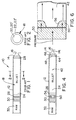
- an apparatus for extruding a superconductor rod includes a liner 12, which is a circular cylinder, connected to a cone 14 that converges to an orifice 16 of an extrusion die.
- the rear end 24 of the billet 18 has a capping lid or disk 26, also of copper, and the front end of the billet 18 has a capping nose or lid 28 that includes a forward taper somewhat paralleling the taper of the cone 14.
- a follower block 30 is positioned between the billet 18 and a driving ram 32 of the extrusion apparatus 10.
- the extruded rod 18' has cross-sectional characteristics as illustrated in Fig. 3. At the rear or tail end 24 of the billet, "tubing" has occurred before a steady state cross-section 36 begins. Copper from the sheath or matrix material is drawn into the core center 38 and more than 6% of the billet must be cropped off before the tubing end effect disappears.
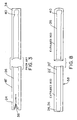
- a billet 42 which is substantially similar to the billet 18 of Fig. 1, is inserted in the liner 12 for extrusion into a superconducting rod 58. Portions of the billet 42 that are similar to those in billet 18 are given the same reference numerals in the following description.
- the billet 42 includes a core 20 surrounded by a sheath 22 as in Fig. 2.
- a disk or lid 26 caps the sheathed core at the end 24 proximate the ram 32 and a lid 44 encloses the sheathed core at the end proximate the orifice 16.
- the lid 44 is not tapered as is the lid 28 in Fig. 1.
- a second disk 46 connects to the lid 44 to provide, in combination, what is conveniently called a "stepped nose" 48. As illustrated in Fig. 4, the leading edge of the second disk 46 of the stepped nose 48 will initially press against the cone 14 when the ram 32 is activated.
- An annular ring or donut 50 is placed in the liner 12 between the follower block 30 and the rear lid 26 of the composite billet 42.
- the composite billet 42 with the stepped nose 48 including the second disk 46, is placed at an elevated temperature in the liner 12, with an unheated donut 50 at the tail end 24.
- the billet is upset, that is, it expands to fill the liner 12 where clearance may exist.
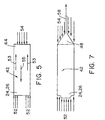
- Illustrated in Fig. 5 is a free body diagram of the billet 42 itself, less the second disk 46.
- An annular ring of forces 52 is applied by the donut 50 to the rear end 24, 26 of the billet 42, whereas at the front end lid 44 of the billet 42, the second disk 46 applies opposite reactive forces 54 to the billet 42.
- the outside diameter of the second disk 46 at the stepped nose 48 is less than the outside diameter of the billet 42 and of the donut 50.
- the extruded rod 58 is of substantially reduced diameter as a result of passing through the orifice 16 and still includes a sheath 22' of conductive material, for example copper and a central superconducting core 20', surrounded by a diffusion barrier (not shown) of Nb or Ta, as described above. As stated, the process may be practiced on monofilament and multifilament composite billets.
- the extent of the distortion in physical characteristics is also dependent upon extrusion parameters such as die angle, percentage of area reduction, speed of extrusion and coefficient of friction.
- the pre-extrusion upset or backward material flow in the liner 12 optimizes the flow profile of the front and rear of the billet 42 before the pressure builds up and before the rod 58 emerges through the orifice 16.
- movement occurs simultaneously in three regions within the liner 12. Namely, the billet 42 upsets and void spaces in the liner 12 are eliminated.
- Pressure transmitted through the donut 50 begins material flowing into the cone 14 leading to the orifice 16. Finally, back flow occurs into the central opening 56 of the donut 50 causing the center portion of the billet 42 to upset, away from the orifice 16.
- the stepped nose 48 and the donut 50 complement each other in providing the upset of material and back flow that fills the donut's center 56.
- the area of the disk 46 in the stepped nose 48 is most effective when it approximately equals the area of a central opening 56 in the donut 50, although yield is improved when the disk is greater or less in area than the opening 56.
- the profiles at the rear and forward ends of the billet 42 are set once back flow ceases and actual extrusion of rod 58 begins.
- the amount of usable yield improvement depends upon the donut geometry, material of which the donut is made, and the desired cross-sectional ratio of sheath to superconductor in the finished product.
- the thicknesses of the donut 50 and stepped nose 48 are also important.
- billet diameter was 25.4 cm (10 inches) and length 81.3 cm (32 inches).
- the thickness of the donut 50 was in a range of 3-10% of the billet length and the cross-sectional area of the central opening 56 in the donut 50 was in the range of approximately 45%-65% of the cross-sectional area of the composite billet 42.
- the billets including the stepped nose 48 were preheated to an extrusion temperature of 750°C, while the donut 50 was at room temperature. Extrusion of superconducting rod 58 occurred when the pressure applied at the ram 32 exceeded 9.38 bar (136 PSI).
- the billet can be extruded into a rod approximately 60.96m (200 feet) long and having an outside diameter in the order of approximately 25.4 to 33.02 mm (1.0 to 1.3 inches).
- yield was increased by 6% approximately and when extruding a multifilament billet with a copper to non-copper ratio 3 of approximately 4 to 1, an increase in yield of approximately 3% was achieved.
- pre-machining of the billet 42 and lids prior to insertion in the liner 12 is reduced as plain cylinders without taper are effective with the present method.
- the stepped nose 48 and the donut 50 are made of copper in a preferred embodiment where the "can", sheath and lids on the billet, is also copper.
- the copper for the donut and nose is generally of the same properties as is used in the can. Copper has proven to be strong enough to support the backward upset of material with suitable deformations (Fig. 6), while maintaining its donut characteristics.
- the stepped nose 48 is not a necessity for use in conjunction with the donut 50.
- An improvement in yield may still be achieved when only the donut 50 is used at the tail end 24, 26, of the billet 42.
- An upset process that improves yield is still produced by the opposite reaction of the billet pressing upon the cone 14 prior to actual extrusion of the superconducting rod 58.
- a donut 50 may be placed directly adjacent to the rear end 24 of the billet 42 and the disk 26 may be placed between the donut 50 and the follower block 30.
- the donut 50 becomes integrated in the billet 42.
Landscapes
- Engineering & Computer Science (AREA)
- Manufacturing & Machinery (AREA)
- Superconductors And Manufacturing Methods Therefor (AREA)
- Metal Extraction Processes (AREA)
- Press-Shaping Or Shaping Using Conveyers (AREA)
Claims (15)
- Verfahren zum Extrudieren eines Vorformlings, um einen supraleitenden Stab zu erzeugen, umfassend die folgenden Schritte:dadurch gekennzeichnet, daß der Verbundvorformling am ersten Vorformlingende (24) mit einem ersten Druck beaufschlagt wird, wobei der erste Druck auf eine ringförmige erste Fläche der ersten leitenden Metallkappe (26) aufgebracht wird, welche von einem Querschnittsmittelpunkt des Verbundvorformlings entfernt liegt, der erste Druck auf ein Maß erhöht wird, welches bewirkt, daß der Verbundvorformling gegen das Extrusionsöffnungmittel (16) gedrückt wird, und welches einen Stauchfluß des Verbundvorformlings zum ersten Vorformlingende hin in einem Bereich, welcher den Querschnittsmittelpunkt des Verbundvorformlings umfaßt, bewirkt, und daß ein mittiger Abschnitt des Verbundvorformlings zum ersten Stabende hinbewegt wird, wenn der erste Druck aufgebracht wird.(a) Vorsehen eines im allgemeinen zylindrischen Supraleiterkerns (20), welcher einen leitenden Metallmantel (22) entlang seiner Länge und eine erste leitende Metallkappe (26) an einem ersten Ende (24) und eine zweite leitenden Metallkappe (44) an einem zweiten Ende (14) aufweist, wobei der Mantel und die Kappen, den Supraleiterkern umschließen und einen Verbundvorformling (42) bilden;(b) Anordnen des Verbundvorformlings (42) in einer zylindrischen Auskleidung (12), welche in einem Extrusionsöffnungsmittel (16) endet, wobei das zweite Ende und die zweite Kappe des Verbundvorformlings in der Nähe des Öffnungsmittels (16) angeordnet werden;
- Verfahren nach Anspruch 1, wobei das Drücken gegen das Öffnungsmittel (16) konzentriert wird, um einen reaktiven zweiten Druck auf das zweite Vorformlingende (14) in einer Richtung, welche dem ersten Druck entgegengesetzt ist, zu erzeugen, und wobei der zweite Druck am zweiten Ende auf einer zweiten Fläche aufgebracht wird, welche sich radial vom Querschnitts-Mittelpunkt bis in eine Entfernung von weniger als einem Radius des Verbundvorformlings wegerstreckt, wobei der zweite Druck den Stauchfluß unterstützt und erzeugt.
- Verfahren nach Anspruch 2, wobei die zweite Fläche der Form nach kreisförmig ist.
- Verfahren nach Anspruch 1 oder 2, wobei der Stauchfluß die Länge des mittigen Abschnitts des Verbundvorformlings in die dem ersten Druck entgegengesetzte Richtung streckt.
- Verfahren nach Anspruch 2, wobei eine Summe aus der ersten Fläche und der zweiten Fläche, ungefähr gleich der Querschnittsfläche des Verbundvorformlings vor dem Aufbringen des ersten und des zweiten Druckes ist.
- Verfahren nach Anspruch 6, wobei die erste ringförmige Fläche in einem Bereich von ungefähr 35 % bis 55 % der Querschnittsfläche des Verbundvorformlings liegt.
- Verfahren nach Anspruch 1, wobei der Mantel einen ringförmigen Querschnitt aufweist, wobei der ringförmige Querschnitt des Mantels der Größenordnung nach ungefähr 25-50 % der Querschnittsfläche des Verbundvorformlings ausmacht.
- Verfahren nach Anspruch 1, wobei das Extrusionsöffnungsmittel einen konvergenten Konus (14) umfaßt, welcher in einer Extrusionsöffnung (16) endet.
- Verfahren nach Anspruch 1, wobei der im allgemeinen zylindrische Supraleitervorformling eine abgestufte Nase (48) aufweist, welche die zweite leitende Metallkappe (44) und eine Scheibe (46) am zweiten Ende umfaßt, wobei die Scheibe einen Durchmesser aufweist, der kleiner als der Verbundvorformling ist;wobei ein einen kreisförmigen Querschnitt aufweisender Ring (50) in der Auskleidung (12) dem ersten Ende des Vorformlings benachbart angeordnet wird;der erste Druck auf dem einen kreisförmigen Querschnitt aufweisenden Ring (50) am ersten Vorformlingende aufgebracht wird; undder mittige Abschnitt des Verbundvorformlings zu dem einen kreisförmigen Querschnitt aufweisenden Ring (50) hinbewegt wird, wenn der erste Druck aufgebracht wird.
- Verfahren nach Anspruch 10, des weiteren umfassend den Schritt des Anordnens eines Backenblocks (30) zwischen dem einen kreisförmigen Querschnitt aufweisenden Ring (50) und einer Quelle des ersten Drucks (32).
- Verfahren nach Anspruch 10, wobei sich der Stauchfluß in eine mittige Öffnung (56) des einen kreisförmigen Querschnitt aufweisenden Ringes (50) hinein erstreckt.
- Verfahren nach Anspruch 11, wobei eine Summe aus der Fläche der Scheibe (46) und der Fläche des einen kreisförmigen Querschnitt aufweisenden Ringes (50) annähernd der Querschnittsfläche des Verbundvorformlings vor der Extrusion entspricht.
- Verfahren nach Anspruch 9, wobei der einen kreisförmigen Querschnitt aufweisende Ring (50) der ersten Kappe (26) benachbart auf einer Seite der ersten Kappe, welche vom Supraleiterkern (20) entfernt liegt, angeordnet wird.
- Verfahren nach Anspruch 9, wobei der einen kreisförmigen Querschnitt aufweisende Ring der ersten Kappe benachbart auf einer Seite der ersten Kappe, welche näher beim Supraleiterkern (20) liegt, angeordnet wird.
- Verfahren nach Anspruch 1, wobei ein einen kreisförmigen Querschnitt aufweisender Ring in der Auskleidung dem ersten Ende des Verbundvorformlings benachbart angeordnet wird;wobei der erste Druck auf den einen kreisförmigen Querschnitt aufweisenden Ring am ersten Vorformlingende aufgebracht wird; undein mittiger Abschnitt des Verbundvorformlings zu dem einen kreisförmigen Querschnitt aufweisenden Ring bewegt wird, wenn der erste Druck aufgebracht wird.
Applications Claiming Priority (3)
| Application Number | Priority Date | Filing Date | Title |
|---|---|---|---|
| US332250 | 1994-10-31 | ||
| US08/332,250 US5475915A (en) | 1994-10-31 | 1994-10-31 | Method for increasing extrusion yield in forming a superconducting rod |
| PCT/US1995/014068 WO1996013867A1 (en) | 1994-10-31 | 1995-10-30 | Method of extruding a superconducting rod |
Publications (3)
| Publication Number | Publication Date |
|---|---|
| EP0789936A1 EP0789936A1 (de) | 1997-08-20 |
| EP0789936A4 EP0789936A4 (de) | 1999-03-31 |
| EP0789936B1 true EP0789936B1 (de) | 2001-08-22 |
Family
ID=23297405
Family Applications (1)
| Application Number | Title | Priority Date | Filing Date |
|---|---|---|---|
| EP95937678A Expired - Lifetime EP0789936B1 (de) | 1994-10-31 | 1995-10-30 | Verfahren zum strangpressen eines supraleitenden stabes |
Country Status (6)
| Country | Link |
|---|---|
| US (1) | US5475915A (de) |
| EP (1) | EP0789936B1 (de) |
| AT (1) | ATE204679T1 (de) |
| DE (1) | DE69522337T2 (de) |
| FI (1) | FI971805A7 (de) |
| WO (1) | WO1996013867A1 (de) |
Families Citing this family (2)
| Publication number | Priority date | Publication date | Assignee | Title |
|---|---|---|---|---|
| US7752734B2 (en) * | 2005-11-08 | 2010-07-13 | Supramagnetics, Inc. | Method for manufacturing superconductors |
| DE102006045234B3 (de) * | 2006-09-26 | 2008-03-06 | Wieland-Werke Ag | Pressbolzen oder Pressblock und Verfahren zum Erwärmen eines Pressbolzens oder Pressblocks in einem Stoßofen |
Family Cites Families (13)
| Publication number | Priority date | Publication date | Assignee | Title |
|---|---|---|---|---|
| US3471925A (en) * | 1965-11-17 | 1969-10-14 | Avco Corp | Composite superconductive conductor and method of manufacture |
| NL132696C (de) * | 1966-05-20 | |||
| GB1170645A (en) * | 1967-09-28 | 1969-11-12 | Imp Metal Ind Kynoch Ltd | Improvements relating to Electrical Conductors |
| CH482325A (de) * | 1968-04-05 | 1969-11-30 | Bbc Brown Boveri & Cie | Verfahren zur Herstellung von supraleitenden metallischen Leitern |
| BE755928A (fr) * | 1969-09-10 | 1971-02-15 | Whittaker Corp | Procede de fabrication de supraconducteurs |
| US3837066A (en) * | 1973-02-14 | 1974-09-24 | Atomic Energy Commission | Method of extruding aluminum coated nb-ti |
| US5116429A (en) * | 1990-05-17 | 1992-05-26 | Composite Materials Technology, Inc. | Superconducting wire |
| JPH04129105A (ja) * | 1990-09-19 | 1992-04-30 | Furukawa Electric Co Ltd:The | 銅安定化極細多芯超電導線の製造方法 |
| JPH04259709A (ja) * | 1991-02-12 | 1992-09-16 | Furukawa Electric Co Ltd:The | 超電導線の製造方法 |
| JPH04292811A (ja) * | 1991-03-20 | 1992-10-16 | Sumitomo Electric Ind Ltd | 酸化物超電導線の製造方法 |
| JPH04306512A (ja) * | 1991-04-02 | 1992-10-29 | Furukawa Electric Co Ltd:The | 複合超電導線およびその製造方法 |
| JPH0576926A (ja) * | 1991-07-22 | 1993-03-30 | Furukawa Electric Co Ltd:The | 押出用超電導複合ビレツト |
| JPH05307917A (ja) * | 1992-04-28 | 1993-11-19 | Furukawa Electric Co Ltd:The | 超電導線の製造方法 |
-
1994
- 1994-10-31 US US08/332,250 patent/US5475915A/en not_active Expired - Lifetime
-
1995
- 1995-10-30 AT AT95937678T patent/ATE204679T1/de active
- 1995-10-30 DE DE69522337T patent/DE69522337T2/de not_active Expired - Lifetime
- 1995-10-30 EP EP95937678A patent/EP0789936B1/de not_active Expired - Lifetime
- 1995-10-30 FI FI971805A patent/FI971805A7/fi unknown
- 1995-10-30 WO PCT/US1995/014068 patent/WO1996013867A1/en not_active Ceased
Also Published As
| Publication number | Publication date |
|---|---|
| WO1996013867A1 (en) | 1996-05-09 |
| DE69522337D1 (de) | 2001-09-27 |
| EP0789936A1 (de) | 1997-08-20 |
| FI971805L (fi) | 1997-06-25 |
| FI971805A7 (fi) | 1997-06-25 |
| US5475915A (en) | 1995-12-19 |
| DE69522337T2 (de) | 2002-01-03 |
| EP0789936A4 (de) | 1999-03-31 |
| ATE204679T1 (de) | 2001-09-15 |
| FI971805A0 (fi) | 1997-04-28 |
Similar Documents
| Publication | Publication Date | Title |
|---|---|---|
| US4928507A (en) | Methods and apparatus for manufacturing seamless tube | |
| US3631586A (en) | Manufacture of copper-clad aluminum rod | |
| US4521360A (en) | Methods of compaction by incremental radial compression and/or low-ratio extrusion | |
| EP0789936B1 (de) | Verfahren zum strangpressen eines supraleitenden stabes | |
| US2639809A (en) | Extrusion of continuous metal articles | |
| US6294738B1 (en) | Silver and silver alloy articles | |
| US5222284A (en) | Apparatus for making co-axial cable | |
| US4967583A (en) | Method of manufacturing extruded seamless hollow materials | |
| JPS6317526B2 (de) | ||
| US2380722A (en) | Method of and apparatus for making articles | |
| WO1996000448A1 (en) | Superconductor with high volume copper and a method of making the same | |
| US3440853A (en) | Metal extrusion method | |
| US3767368A (en) | Method of and means for commencing a deforming operation, e. g., hydrostatic extrusion of a billet | |
| US5271149A (en) | Method for producing a co-axial cable | |
| JPS61143112A (ja) | 合成樹脂の固相押出成形方法 | |
| JPS6145922Y2 (de) | ||
| EP0822016B1 (de) | Verfahren zur Herstellung eines bimetallischen Materials | |
| JPS5847510A (ja) | 2段押出装置 | |
| JPS6251687B2 (de) | ||
| Siergiej | Extrusion of Beryllium Structural Shapes | |
| JPH05307917A (ja) | 超電導線の製造方法 | |
| HU176898B (en) | Tool for extruding advantageously copper and aluminium alloys | |
| US3123893A (en) | Method of working sheet | |
| RU2058844C1 (ru) | Способ непрерывного прессования заготовок и устройство для его осуществления | |
| US3924429A (en) | Method and apparatus for reducing extrusion start-up pressure |
Legal Events
| Date | Code | Title | Description |
|---|---|---|---|
| PUAI | Public reference made under article 153(3) epc to a published international application that has entered the european phase |
Free format text: ORIGINAL CODE: 0009012 |
|
| 17P | Request for examination filed |
Effective date: 19970524 |
|
| AK | Designated contracting states |
Kind code of ref document: A1 Designated state(s): AT BE CH DE DK ES FR GB GR IE IT LI LU MC NL PT SE |
|
| A4 | Supplementary search report drawn up and despatched |
Effective date: 19990216 |
|
| AK | Designated contracting states |
Kind code of ref document: A4 Designated state(s): AT BE CH DE DK ES FR GB GR IE IT LI LU MC NL PT SE |
|
| 17Q | First examination report despatched |
Effective date: 19990630 |
|
| GRAG | Despatch of communication of intention to grant |
Free format text: ORIGINAL CODE: EPIDOS AGRA |
|
| GRAG | Despatch of communication of intention to grant |
Free format text: ORIGINAL CODE: EPIDOS AGRA |
|
| GRAH | Despatch of communication of intention to grant a patent |
Free format text: ORIGINAL CODE: EPIDOS IGRA |
|
| GRAH | Despatch of communication of intention to grant a patent |
Free format text: ORIGINAL CODE: EPIDOS IGRA |
|
| GRAA | (expected) grant |
Free format text: ORIGINAL CODE: 0009210 |
|
| AK | Designated contracting states |
Kind code of ref document: B1 Designated state(s): AT BE CH DE DK ES FR GB GR IE IT LI LU MC NL PT SE |
|
| PG25 | Lapsed in a contracting state [announced via postgrant information from national office to epo] |
Ref country code: NL Free format text: LAPSE BECAUSE OF FAILURE TO SUBMIT A TRANSLATION OF THE DESCRIPTION OR TO PAY THE FEE WITHIN THE PRESCRIBED TIME-LIMIT Effective date: 20010822 Ref country code: BE Free format text: LAPSE BECAUSE OF FAILURE TO SUBMIT A TRANSLATION OF THE DESCRIPTION OR TO PAY THE FEE WITHIN THE PRESCRIBED TIME-LIMIT Effective date: 20010822 Ref country code: AT Free format text: LAPSE BECAUSE OF FAILURE TO SUBMIT A TRANSLATION OF THE DESCRIPTION OR TO PAY THE FEE WITHIN THE PRESCRIBED TIME-LIMIT Effective date: 20010822 |
|
| REF | Corresponds to: |
Ref document number: 204679 Country of ref document: AT Date of ref document: 20010915 Kind code of ref document: T |
|
| REG | Reference to a national code |
Ref country code: CH Ref legal event code: NV Representative=s name: RIEDERER HASLER & PARTNER PATENTANWAELTE AG Ref country code: CH Ref legal event code: EP |
|
| REF | Corresponds to: |
Ref document number: 69522337 Country of ref document: DE Date of ref document: 20010927 |
|
| REG | Reference to a national code |
Ref country code: IE Ref legal event code: FG4D |
|
| PGFP | Annual fee paid to national office [announced via postgrant information from national office to epo] |
Ref country code: SE Payment date: 20011018 Year of fee payment: 7 Ref country code: GB Payment date: 20011018 Year of fee payment: 7 |
|
| PGFP | Annual fee paid to national office [announced via postgrant information from national office to epo] |
Ref country code: MC Payment date: 20011019 Year of fee payment: 7 |
|
| PGFP | Annual fee paid to national office [announced via postgrant information from national office to epo] |
Ref country code: DK Payment date: 20011022 Year of fee payment: 7 Ref country code: CH Payment date: 20011022 Year of fee payment: 7 |
|
| PGFP | Annual fee paid to national office [announced via postgrant information from national office to epo] |
Ref country code: LU Payment date: 20011024 Year of fee payment: 7 |
|
| PGFP | Annual fee paid to national office [announced via postgrant information from national office to epo] |
Ref country code: NL Payment date: 20011026 Year of fee payment: 7 |
|
| PGFP | Annual fee paid to national office [announced via postgrant information from national office to epo] |
Ref country code: IE Payment date: 20011030 Year of fee payment: 7 |
|
| PGFP | Annual fee paid to national office [announced via postgrant information from national office to epo] |
Ref country code: ES Payment date: 20011108 Year of fee payment: 7 |
|
| PGFP | Annual fee paid to national office [announced via postgrant information from national office to epo] |
Ref country code: BE Payment date: 20011116 Year of fee payment: 7 |
|
| PG25 | Lapsed in a contracting state [announced via postgrant information from national office to epo] |
Ref country code: SE Free format text: LAPSE BECAUSE OF FAILURE TO SUBMIT A TRANSLATION OF THE DESCRIPTION OR TO PAY THE FEE WITHIN THE PRESCRIBED TIME-LIMIT Effective date: 20011122 Ref country code: PT Free format text: LAPSE BECAUSE OF FAILURE TO SUBMIT A TRANSLATION OF THE DESCRIPTION OR TO PAY THE FEE WITHIN THE PRESCRIBED TIME-LIMIT Effective date: 20011122 Ref country code: DK Free format text: LAPSE BECAUSE OF FAILURE TO SUBMIT A TRANSLATION OF THE DESCRIPTION OR TO PAY THE FEE WITHIN THE PRESCRIBED TIME-LIMIT Effective date: 20011122 |
|
| PG25 | Lapsed in a contracting state [announced via postgrant information from national office to epo] |
Ref country code: GR Free format text: LAPSE BECAUSE OF FAILURE TO SUBMIT A TRANSLATION OF THE DESCRIPTION OR TO PAY THE FEE WITHIN THE PRESCRIBED TIME-LIMIT Effective date: 20011123 |
|
| REG | Reference to a national code |
Ref country code: GB Ref legal event code: IF02 |
|
| ET | Fr: translation filed | ||
| NLV1 | Nl: lapsed or annulled due to failure to fulfill the requirements of art. 29p and 29m of the patents act | ||
| PG25 | Lapsed in a contracting state [announced via postgrant information from national office to epo] |
Ref country code: ES Free format text: LAPSE BECAUSE OF FAILURE TO SUBMIT A TRANSLATION OF THE DESCRIPTION OR TO PAY THE FEE WITHIN THE PRESCRIBED TIME-LIMIT Effective date: 20020228 |
|
| PLBE | No opposition filed within time limit |
Free format text: ORIGINAL CODE: 0009261 |
|
| STAA | Information on the status of an ep patent application or granted ep patent |
Free format text: STATUS: NO OPPOSITION FILED WITHIN TIME LIMIT |
|
| 26N | No opposition filed | ||
| PG25 | Lapsed in a contracting state [announced via postgrant information from national office to epo] |
Ref country code: LU Free format text: LAPSE BECAUSE OF NON-PAYMENT OF DUE FEES Effective date: 20021030 Ref country code: IE Free format text: LAPSE BECAUSE OF NON-PAYMENT OF DUE FEES Effective date: 20021030 Ref country code: GB Free format text: LAPSE BECAUSE OF NON-PAYMENT OF DUE FEES Effective date: 20021030 |
|
| PG25 | Lapsed in a contracting state [announced via postgrant information from national office to epo] |
Ref country code: LI Free format text: LAPSE BECAUSE OF NON-PAYMENT OF DUE FEES Effective date: 20021031 Ref country code: CH Free format text: LAPSE BECAUSE OF NON-PAYMENT OF DUE FEES Effective date: 20021031 |
|
| PG25 | Lapsed in a contracting state [announced via postgrant information from national office to epo] |
Ref country code: MC Free format text: LAPSE BECAUSE OF NON-PAYMENT OF DUE FEES Effective date: 20030501 |
|
| REG | Reference to a national code |
Ref country code: CH Ref legal event code: PL |
|
| GBPC | Gb: european patent ceased through non-payment of renewal fee | ||
| REG | Reference to a national code |
Ref country code: IE Ref legal event code: MM4A |
|
| PG25 | Lapsed in a contracting state [announced via postgrant information from national office to epo] |
Ref country code: IT Free format text: LAPSE BECAUSE OF NON-PAYMENT OF DUE FEES Effective date: 20051030 |
|
| PGFP | Annual fee paid to national office [announced via postgrant information from national office to epo] |
Ref country code: FR Payment date: 20080930 Year of fee payment: 14 |
|
| REG | Reference to a national code |
Ref country code: FR Ref legal event code: ST Effective date: 20100630 |
|
| PG25 | Lapsed in a contracting state [announced via postgrant information from national office to epo] |
Ref country code: FR Free format text: LAPSE BECAUSE OF NON-PAYMENT OF DUE FEES Effective date: 20091102 |
|
| PGFP | Annual fee paid to national office [announced via postgrant information from national office to epo] |
Ref country code: DE Payment date: 20141024 Year of fee payment: 20 |
|
| REG | Reference to a national code |
Ref country code: DE Ref legal event code: R071 Ref document number: 69522337 Country of ref document: DE |