EP0789481A2 - Système et appareil pour la lecture d'images de radiation - Google Patents
Système et appareil pour la lecture d'images de radiation Download PDFInfo
- Publication number
- EP0789481A2 EP0789481A2 EP97200268A EP97200268A EP0789481A2 EP 0789481 A2 EP0789481 A2 EP 0789481A2 EP 97200268 A EP97200268 A EP 97200268A EP 97200268 A EP97200268 A EP 97200268A EP 0789481 A2 EP0789481 A2 EP 0789481A2
- Authority
- EP
- European Patent Office
- Prior art keywords
- screen
- read out
- erased
- light
- erasing
- Prior art date
- Legal status (The legal status is an assumption and is not a legal conclusion. Google has not performed a legal analysis and makes no representation as to the accuracy of the status listed.)
- Granted
Links
Images

Classifications
-
- G—PHYSICS
- G03—PHOTOGRAPHY; CINEMATOGRAPHY; ANALOGOUS TECHNIQUES USING WAVES OTHER THAN OPTICAL WAVES; ELECTROGRAPHY; HOLOGRAPHY
- G03B—APPARATUS OR ARRANGEMENTS FOR TAKING PHOTOGRAPHS OR FOR PROJECTING OR VIEWING THEM; APPARATUS OR ARRANGEMENTS EMPLOYING ANALOGOUS TECHNIQUES USING WAVES OTHER THAN OPTICAL WAVES; ACCESSORIES THEREFOR
- G03B42/00—Obtaining records using waves other than optical waves; Visualisation of such records by using optical means
- G03B42/02—Obtaining records using waves other than optical waves; Visualisation of such records by using optical means using X-rays
Definitions
- the present invention is in the field of digital radiography.
- the invention more particularly relates to a method and an apparatus for determining the amount of residual energy left in a photostimulable phosphor screen after image read out.
- a photostimulable phosphor screen comprises a layer of photostimulable luminescent material which comprises a phosphor, for example a europium-activated barium fluoro-halide, and a binder.
- the phosphor has the characteristic that it can be energised to an excited state by X-rays, and can then be stimulated by light within a first wavelength range to return to the ground state with the emission of light within a second wavelength range.
- the stimulating radiation is arranged to have a different wavelength from the emitted light.
- the stimulating light is situated within the range of 600-700 nm and the emitted light is situated within the range of 350-450 nm.
- the screen In order to read the image stored in the exposed screen, the screen is transported past a scanning station where it is two-dimensionally scanned with stimulating light.
- stimulating light beam of a wavelength within said first or stimulating wavelength range is deflected so as to scan the screen in a first direction (called main scan direction) while the screen is transported in a second direction that is perpendicular to the main scan direction.
- a light guide member onto an opto-electric transducer such as a photomultiplier that converts the emitted light into a corresponding electric signal.
- an opto-electric transducer such as a photomultiplier that converts the emitted light into a corresponding electric signal.
- a filter is positioned either at the entrance face of the light guide or between the output of the light guide and the opto-electrical transducer for preventing stimulating light from being detected by the opto-electrical transducer.
- the stimulable phosphor screen After read out the stimulable phosphor screen should be free from the previously stored radiation image so that it can be re-used.
- the stored radiation energy is not completely eliminated by the read out process.
- it is fed from the read out station to an erasing station where the part of the energy still remaining in the phosphor after read out is erased by subjecting the screen to a uniform illumination by means of erasing light.
- Non-optimal adjustment of the applied amount of erasing energy may be the result of the fact that the period of time during which a photostimulable phosphor screen is subjected to erasing light is too short (for example as a result of incorrect transport speed of the screen), or that the amount of energy emitted by the erasing light sources to the phosphor screen to be erased does not correspond with the set amount (for example due to a failing lamp) etc.
- the apparatus comprises a circulatory feed system for feeding photostimulable phosphor sheets along a pre-determined circulatory feed path comprising in sequence an exposure unit, a read out unit and an erasure unit. Prior to successive recording of images on the sheets, any remaining images are erased. After erasure the sheet is again read out and the signal level is thresholded. If the signal level is higher than a certain level, then the remaining image is erased again in the image erase unit. The erasure step is repeated until the remaining image is sufficiently small.
- the invention provides a method of reading a radiation image stored in a photostimulable phosphor screen comprising the steps of
- the resolution at which the erased screen or at least part thereof is scanned is lower than the resolution at which the scanning of the screen is performed during read out prior to erasure.
- a screen is scanned by deflecting a light beam in a first direction and transporting the screen in a second direction that is perpendicular to said first direction.
- the resolution at which the screen is scanned in step (5) is decreased relative to the resolution at which the screen is scanned at step (1) by adjusting the speed at which the erased screen is transported in said second direction during step (5) to be higher than the speed at which the screen is transported in said second direction in step (1).
- This loss of throughput of the apparatus can be limited to an acceptable extent if the second scanning of the erased screen is performed at a lower resolution than the scanning of the screen before erasure (implemented e.g. by increasing the speed at which the screen is transported in the sub-scan direction).
- the energy remaining in the screen after erasure should be sufficiently small.
- the signal level detected when the screen is read a second time at highest machine sensitivity is a 1000 times smaller than the maximum dynamic range of the read out apparatus at said highest sensitivity.
- step (5) In case the signal resulting from step (5) exceeds a preset threshold signal value, this indicates that the screen has not been erased to an adequate extent allowing re-use of the screen. In this case the screen is either to be erased once more or it is to be decided that the particular screen cannot be re-used.
- Another aspect of the present invention relates to an apparatus for reading a radiation image that has been stored in a photostimulable phosphor screen comprising
- the apparatus of the above-described kind has a single read-out unit.
- Such an apparatus is particularly advantageous from the viewpoint of economy and compact design.
- a read out unit is preferably located in between the input of the apparatus and the erasing unit.
- the preferred embodiment of the apparatus further comprises means for transporting the screen from the input unit through the read out unit to the erasure unit and means for reversing the transport direction so that a screen is transported from the erasure unit through the read out unit to the input unit.
- the means for transporting the screen transport it substantially in a single plane.
- This apparatus is as follows. First the screen is taken out of the cassette at the input unit and fed into the read out unit where it is scanned by means of stimulating radiation. Light emitted upon stimulation is detected and converted into an image signal.
- the transport direction is reversed and the read out and erased screen is again transported through the read out unit to the input unit where it is put back into the cassette.
- the erased screen is scanned by means of stimulating radiation and, again, the light emitted upon stimulation is detected and converted into an electric signal. This signal now represents the residual image left in the screen after erasure.
- This signal is then applied to an electronic comparator where its value is compared with a threshold signal representative of a maximum energy level that is allowed to be detected on the screen after erasure.
- the photostimulable phosphor screen is conveyed in a cassette of the type comprising a flat substantially rigid base plate and a cap for the base plate which is releasably securable to the base plate so as light-tightly to cover a layer of photostimulable phosphor material applied to a face of the base plate.
- the cassette is opened by lifting the cap.
- the cap is held in a position outside the read out apparatus.
- the base plate conveying the photostimulable phosphor screen is transported through the read out and erasing units in the same way as described higher for a screen that is entirely taken out of the cassette.
- Read out of the erased screen is preferably performed at a lower resolution than the resolution at which the screen is read out the first time (prior to the erasure of the screen).
- the lower resolution can be obtained by adjusting the speed of the scanning movement.
- the number of lines in the sub-scan direction (direction into which the screen is transported) scanned during read out of the erased screen is reduced relative to the number of lines scanned during read out of the screen prior to erasure.
- the slow scan speed is reduced to 100 lines during the read out step of the erased screen.
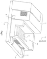
- the apparatus 10 generally comprises a housing 12 mounted on a base 11, and has a cassette input station 13 for receipt of a stack of image-wise exposed cassettes and for loading and unloading cassettes.
- This station has in its bottom a rectangular opening 14 forming the cassette entry port of the apparatus.
- a lighttight roller shutter 15 closes this port.
- the base of the apparatus has on its right-hand side a platform 16 for receipt of a processed cassette and also for introducing a cassette in the apparatus which should occasionally by-pass the cassettes stacked in station 13.
- the inlet port of this platform is closed by a lighttight curtain 17 or the like.
- Control panel 8 comprises the usual control provisions for operation of the apparatus.
- Fig. 2 is a diagrammatic longitudinal unital view of the apparatus according to Fig. 1 showing the following elements:
- the operation of the device is as follows. A cassette conveying a screen that has been exposed to an X-ray image is placed in the cassette input unit 13.
- the cover of the cassette conveying the photostimulable phosphor screen is completely removable from the base thereby to expose a photostimulable phosphor layer applied on top of its base.
- the base comprises a rigid bottom plate onto which a photostimulable phosphor layer is provided.
- the photostimulable phosphor material may be directly coated on the base but suitably is coated on a flexible support such as a polyethylene terephthalate sheet which then is adhered to the base.
- the base has four rectangular recesses into which one part of interlocking patches, e.g. patches sold under the trade mark Dual Lock, manufactured by 3M, are fitted. The co-operating interlocking patches are fitted on corresponding places of the cover.
- Opening of the cassette may occur by means of pairs of fingers in the form of flat leaves or the like engaging grooves of the recesses accessible on the outside of the cassette. More details about suitable cassettes and their locking mechanism can be found in our co-pending application EP 0 567 175 A1.
- the cassette is opened by lifting the cover and the base conveying a photostimulable phosphor screen is fed into the read out unit 18.
- the screen is line wise scanned by means of laser light emitted by a HeNe laser and deflected by a galvanometer mirror 19 to scan the screen in a first or main scan direction while the screen is transported by carriage and belt assembly 31, 26 in a second or subscan direction.
- the screen is transported in the sub-scan direction at approximately 12 mm/sec so that 2500 lines are scanned.
- Light emitted by the screen upon stimulation is guided by light guide 23 onto a photomultiplier 24 and subsequently converted into a digital signal representation of the radiation image.
- the read out screen is conveyed to the erasing unit 25 where it is subjected to an illumination by means of light emitted by a quartz tungsten lamp.
- the speed at which the screen is transported through this unit is increased relative to the speed at which the screen was transported through this unit during the first read out step.
- the screen was again stimulated and the light emitted upon stimulation was likewise directed towards the photomultiplier and converted into a digital signal representation.
- the sensitivity of the photomultiplier can be changed stepwise, each of the steps differing by a factor of two.
- Each setting is called a 'sensitivity class setting' in analogy with the notion of 'speed classes' used in connection with conventional radiographic film.
- the photomultiplier voltage was adjusted so that its sensitivity corresponds with the maximum setable sensitivity of the described device, i.e. a class 1200 setting.
- the digital signal representation obtained by scanning the erased screen was then applied to an electronic signal comparator (not shown) where it was compared with a threshold signal so as to generate a signal indicating whether the signal read out from the erased screen was greater than the threshold signal thereby indicating that the screen had not been erased to a sufficient erasure depth.
- the value of the threshold signal was set to correspond with 1/1000 of the dynamic range of the read out apparatus at the set sensitivity class adjustment.
- the transport direction of the belt was once more reversed and the screen was once again transported through the erasing unit 25 and was once more subjected to erasing light.
- Fig. 1 is a perspective view of one embodiment of a scanning apparatus according to the present invention, wherein
- Fig. 2 is a diagrammatic longitudinal view of the scanning apparatus according to Fig. 1 wherein
Landscapes
- Physics & Mathematics (AREA)
- General Physics & Mathematics (AREA)
- Radiography Using Non-Light Waves (AREA)
- Transforming Light Signals Into Electric Signals (AREA)
- Apparatus For Radiation Diagnosis (AREA)
Priority Applications (1)
| Application Number | Priority Date | Filing Date | Title |
|---|---|---|---|
| EP19970200268 EP0789481B1 (fr) | 1996-02-08 | 1997-01-31 | Système et appareil pour la lecture d'images de radiation |
Applications Claiming Priority (3)
| Application Number | Priority Date | Filing Date | Title |
|---|---|---|---|
| EP96200273 | 1996-02-08 | ||
| EP96200273 | 1996-02-08 | ||
| EP19970200268 EP0789481B1 (fr) | 1996-02-08 | 1997-01-31 | Système et appareil pour la lecture d'images de radiation |
Publications (3)
| Publication Number | Publication Date |
|---|---|
| EP0789481A2 true EP0789481A2 (fr) | 1997-08-13 |
| EP0789481A3 EP0789481A3 (fr) | 1997-09-24 |
| EP0789481B1 EP0789481B1 (fr) | 2004-04-07 |
Family
ID=26142464
Family Applications (1)
| Application Number | Title | Priority Date | Filing Date |
|---|---|---|---|
| EP19970200268 Expired - Lifetime EP0789481B1 (fr) | 1996-02-08 | 1997-01-31 | Système et appareil pour la lecture d'images de radiation |
Country Status (1)
| Country | Link |
|---|---|
| EP (1) | EP0789481B1 (fr) |
Citations (2)
| Publication number | Priority date | Publication date | Assignee | Title |
|---|---|---|---|---|
| EP0345832A2 (fr) | 1984-10-30 | 1989-12-13 | Fuji Photo Film Co., Ltd. | Méthode et dispositif pour enregistrer et lire l'information d'une image de radiation |
| EP0567175A1 (fr) | 1992-04-21 | 1993-10-27 | Agfa-Gevaert N.V. | Cassette pour radiographie PSL |
Family Cites Families (2)
| Publication number | Priority date | Publication date | Assignee | Title |
|---|---|---|---|---|
| JPS6129834A (ja) * | 1984-07-20 | 1986-02-10 | Fuji Photo Film Co Ltd | 放射線画像情報記録読取装置 |
| JP3260028B2 (ja) * | 1993-12-27 | 2002-02-25 | 富士写真フイルム株式会社 | 蓄積性蛍光体シートの残留ノイズ消去方法および装置 |
-
1997
- 1997-01-31 EP EP19970200268 patent/EP0789481B1/fr not_active Expired - Lifetime
Patent Citations (2)
| Publication number | Priority date | Publication date | Assignee | Title |
|---|---|---|---|---|
| EP0345832A2 (fr) | 1984-10-30 | 1989-12-13 | Fuji Photo Film Co., Ltd. | Méthode et dispositif pour enregistrer et lire l'information d'une image de radiation |
| EP0567175A1 (fr) | 1992-04-21 | 1993-10-27 | Agfa-Gevaert N.V. | Cassette pour radiographie PSL |
Also Published As
| Publication number | Publication date |
|---|---|
| EP0789481A3 (fr) | 1997-09-24 |
| EP0789481B1 (fr) | 2004-04-07 |
Similar Documents
| Publication | Publication Date | Title |
|---|---|---|
| US4410799A (en) | Device for controlling radiation image information read out gain | |
| CA1220566A (fr) | Appareil d'enregistrement et de visionnement d'images | |
| US4859849A (en) | Radiation image recording and read-out apparatus | |
| US5818065A (en) | Radiation image readout method and apparatus | |
| US4786808A (en) | Residual image erasing apparatus for stimulable phosphor sheet | |
| US5162919A (en) | Light beam scanning apparatus using sequentially activated shutters and light sources | |
| JP2756377B2 (ja) | 放射線画像情報読取装置 | |
| US4931641A (en) | Radiation image read-out apparatus | |
| US5013916A (en) | Method and apparatus for recording and reading out radiation images | |
| EP0172417B1 (fr) | Dispositif pour l'enregistrement et la reproduction d'image de rayonnement | |
| EP0789481B1 (fr) | Système et appareil pour la lecture d'images de radiation | |
| US4908520A (en) | Radiation image recording, read-out and reproducing apparatus | |
| US4947043A (en) | Radiation image recording and read-out apparatus | |
| EP0307937B1 (fr) | Dispositif de reproduction d'image de rayonnement | |
| EP0277506B1 (fr) | Dispositif d'enregistrement et de reproduction d'image de rayonnement | |
| US4939367A (en) | Recording and read-out apparatus | |
| JP2905166B2 (ja) | 放射画像読出し方法及び装置 | |
| EP0284994B1 (fr) | Dispositif pour la reproduction d'image de rayonnement | |
| US5061852A (en) | Radiation image read-out apparatus | |
| US4754137A (en) | Tomographic type panoramic radiation image recording and read-out apparatus | |
| US5202565A (en) | Radiation image information recording and reading apparatus | |
| US4897546A (en) | Radiation image recording, read-out and reproducing apparatus | |
| US4864135A (en) | Radiation image read-out and reproducing apparatus | |
| JP2889989B2 (ja) | 蓄積性蛍光体シートの消去装置および放射線画像読取装置 | |
| JP4165853B2 (ja) | シート体用副走査搬送装置の制御方法 |
Legal Events
| Date | Code | Title | Description |
|---|---|---|---|
| PUAI | Public reference made under article 153(3) epc to a published international application that has entered the european phase |
Free format text: ORIGINAL CODE: 0009012 |
|
| PUAL | Search report despatched |
Free format text: ORIGINAL CODE: 0009013 |
|
| AK | Designated contracting states |
Kind code of ref document: A2 Designated state(s): DE FR GB |
|
| AK | Designated contracting states |
Kind code of ref document: A3 Designated state(s): DE FR GB |
|
| PUAL | Search report despatched |
Free format text: ORIGINAL CODE: 0009013 |
|
| 17P | Request for examination filed |
Effective date: 19980911 |
|
| 17Q | First examination report despatched |
Effective date: 20010730 |
|
| RAP1 | Party data changed (applicant data changed or rights of an application transferred) |
Owner name: AGFA-GEVAERT |
|
| GRAH | Despatch of communication of intention to grant a patent |
Free format text: ORIGINAL CODE: EPIDOS IGRA |
|
| GRAH | Despatch of communication of intention to grant a patent |
Free format text: ORIGINAL CODE: EPIDOS IGRA |
|
| GRAA | (expected) grant |
Free format text: ORIGINAL CODE: 0009210 |
|
| AK | Designated contracting states |
Kind code of ref document: B1 Designated state(s): DE FR GB |
|
| REG | Reference to a national code |
Ref country code: GB Ref legal event code: FG4D |
|
| REF | Corresponds to: |
Ref document number: 69728461 Country of ref document: DE Date of ref document: 20040513 Kind code of ref document: P |
|
| REG | Reference to a national code |
Ref country code: GB Ref legal event code: 746 Effective date: 20040921 |
|
| ET | Fr: translation filed | ||
| REG | Reference to a national code |
Ref country code: FR Ref legal event code: D6 |
|
| PLBE | No opposition filed within time limit |
Free format text: ORIGINAL CODE: 0009261 |
|
| STAA | Information on the status of an ep patent application or granted ep patent |
Free format text: STATUS: NO OPPOSITION FILED WITHIN TIME LIMIT |
|
| 26N | No opposition filed |
Effective date: 20050110 |
|
| REG | Reference to a national code |
Ref country code: GB Ref legal event code: 732E |
|
| REG | Reference to a national code |
Ref country code: FR Ref legal event code: TP |
|
| PGFP | Annual fee paid to national office [announced via postgrant information from national office to epo] |
Ref country code: GB Payment date: 20090126 Year of fee payment: 13 |
|
| PGFP | Annual fee paid to national office [announced via postgrant information from national office to epo] |
Ref country code: FR Payment date: 20090123 Year of fee payment: 13 |
|
| GBPC | Gb: european patent ceased through non-payment of renewal fee |
Effective date: 20100131 |
|
| REG | Reference to a national code |
Ref country code: FR Ref legal event code: ST Effective date: 20100930 |
|
| PG25 | Lapsed in a contracting state [announced via postgrant information from national office to epo] |
Ref country code: FR Free format text: LAPSE BECAUSE OF NON-PAYMENT OF DUE FEES Effective date: 20100201 |
|
| PG25 | Lapsed in a contracting state [announced via postgrant information from national office to epo] |
Ref country code: GB Free format text: LAPSE BECAUSE OF NON-PAYMENT OF DUE FEES Effective date: 20100131 |
|
| PGFP | Annual fee paid to national office [announced via postgrant information from national office to epo] |
Ref country code: DE Payment date: 20111203 Year of fee payment: 16 |
|
| PG25 | Lapsed in a contracting state [announced via postgrant information from national office to epo] |
Ref country code: DE Free format text: LAPSE BECAUSE OF NON-PAYMENT OF DUE FEES Effective date: 20130801 |
|
| REG | Reference to a national code |
Ref country code: DE Ref legal event code: R119 Ref document number: 69728461 Country of ref document: DE Effective date: 20130801 |