EP0789286B1 - Developing apparatus - Google Patents
Developing apparatus Download PDFInfo
- Publication number
- EP0789286B1 EP0789286B1 EP97300761A EP97300761A EP0789286B1 EP 0789286 B1 EP0789286 B1 EP 0789286B1 EP 97300761 A EP97300761 A EP 97300761A EP 97300761 A EP97300761 A EP 97300761A EP 0789286 B1 EP0789286 B1 EP 0789286B1
- Authority
- EP
- European Patent Office
- Prior art keywords
- magnetic
- developer
- developing sleeve
- developer carrier
- guiding
- Prior art date
- Legal status (The legal status is an assumption and is not a legal conclusion. Google has not performed a legal analysis and makes no representation as to the accuracy of the status listed.)
- Expired - Lifetime
Links
- 238000007789 sealing Methods 0.000 claims description 37
- 238000000034 method Methods 0.000 claims description 17
- 230000002093 peripheral effect Effects 0.000 claims description 8
- 238000011144 upstream manufacturing Methods 0.000 claims description 2
- 230000004907 flux Effects 0.000 description 5
- 239000002184 metal Substances 0.000 description 5
- 238000004140 cleaning Methods 0.000 description 2
- 230000000694 effects Effects 0.000 description 2
- 239000013013 elastic material Substances 0.000 description 2
- 239000000696 magnetic material Substances 0.000 description 2
- 230000001105 regulatory effect Effects 0.000 description 2
- 230000035939 shock Effects 0.000 description 2
- 230000015572 biosynthetic process Effects 0.000 description 1
- 239000012141 concentrate Substances 0.000 description 1
- 230000006866 deterioration Effects 0.000 description 1
- 239000006249 magnetic particle Substances 0.000 description 1
- 239000000463 material Substances 0.000 description 1
- 238000012986 modification Methods 0.000 description 1
- 230000004048 modification Effects 0.000 description 1
- 239000002245 particle Substances 0.000 description 1
- 239000003566 sealing material Substances 0.000 description 1
Images

Classifications
-
- G—PHYSICS
- G03—PHOTOGRAPHY; CINEMATOGRAPHY; ANALOGOUS TECHNIQUES USING WAVES OTHER THAN OPTICAL WAVES; ELECTROGRAPHY; HOLOGRAPHY
- G03G—ELECTROGRAPHY; ELECTROPHOTOGRAPHY; MAGNETOGRAPHY
- G03G15/00—Apparatus for electrographic processes using a charge pattern
- G03G15/06—Apparatus for electrographic processes using a charge pattern for developing
- G03G15/08—Apparatus for electrographic processes using a charge pattern for developing using a solid developer, e.g. powder developer
- G03G15/09—Apparatus for electrographic processes using a charge pattern for developing using a solid developer, e.g. powder developer using magnetic brush
- G03G15/0942—Apparatus for electrographic processes using a charge pattern for developing using a solid developer, e.g. powder developer using magnetic brush with means for preventing toner scattering from the magnetic brush, e.g. magnetic seals
-
- G—PHYSICS
- G03—PHOTOGRAPHY; CINEMATOGRAPHY; ANALOGOUS TECHNIQUES USING WAVES OTHER THAN OPTICAL WAVES; ELECTROGRAPHY; HOLOGRAPHY
- G03G—ELECTROGRAPHY; ELECTROPHOTOGRAPHY; MAGNETOGRAPHY
- G03G15/00—Apparatus for electrographic processes using a charge pattern
- G03G15/06—Apparatus for electrographic processes using a charge pattern for developing
Definitions
- the present invention relates to a developing apparatus which developing an electrostatic image on an image bearing member.
- it relates to a developing apparatus in which a focused magnetic field is used to seal the end portions of the developing device.
- a latent image is formed by exposing the selected surface areas of an image bearing member having been uniformly charged, and the thus formed latent image is visualized as a toner image as it is developed with the toner borne on a developer carrier member. Then, the toner image is transferred onto a recording medium to complete a print.
- a developing apparatus for developing a latent image is provided with sealing members for preventing developer (toner) from seeping out of the developing apparatus. They are located at both longitudinal end of a developer carrying rotary member (developing sleeve.
- elastic material such as felt or foamed rubber has been widely used as the material for the sealing member.
- Figure 6 is a section of the essential structure of the sealing member in a conventional developing apparatus
- Figure 7 is a longitudinal section of the structure of the same.
- a developing sleeve 5 as a developer carrier member contains a magnetic roller 6, and is disposed in a toner container 3 as a developer container, being rotatively supported by a sleeve bearing 12 fixed to the toner container 3, as illustrated in Figure 7.
- the toner supplied from the toner container 3 is adhered to the surface of the developing sleeve 5 by the magnetic force of the magnetic roller 6, and form a layer of toner.
- the thickness of the toner layer is regulated by a development blade 7 so that it becomes a predetermined one.
- the adhered toner is conveyed to a point where the distance between a latent image on a photosensitive drum 1 and the layer of the adhered toner on the developing sleeve 5 becomes shortest, and at this point, the toner adheres to the latent image, developing it.
- Both longitudinal ends of the developing sleeve 5 are fitted in an elastic sealing member 8.
- the elastic sealing member 8 is attached to the toner container 3, being positioned substantially behind the developing sleeve 5 as seen from the direction of the photosensitive member 1. As this elastic sealing member 8 is pressed upon the peripheral surface of the developing sleeve 5, toner is prevented from seeping out of the developing apparatus.
- the above structure also has problems.
- the elastic sealing member 8 generates large load as it is pressed upon the peripheral surface of the developing sleeve 5. Further, the elastic sealing member 8 deteriorates through its contact with the developing sleeve 5, losing its ability to seal.
- the toner sometimes enters between the developing sleeve 5 and the elastic sealing member 8. Though the amount of the toner which enters between the two components is very small, it is enough to increase or fluctuate the torque necessary to rotate the developing sleeve. The torque fluctuation disturbs the rotational speed of the developing sleeve 5, which has ill effects on image formation.
- a method for solving the above described problems has been proposed. According to this method, in order to prevent toner from seeping out, a magnetic sealing members is disposed at both longitudinal ends of the developing sleeve 5, in a manner to create a predetermined gap between the developing sleeve 5 and itself.
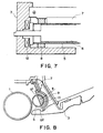
- Figure 8 is a sectional view of a developing apparatus employing a sealing member 9 of magnetic material, depicting the structure thereof.
- the magnetic sealing member 9 is disposed at each longitudinal end of the developing sleeve 5, being attached to the toner container 3 in a manner to hold a predetermined gap g between the peripheral surface of the developing sleeve 5 and itself.
- the developing sleeve 5 contains a magnet 10, generating a magnetic field whose magnetic flux concentrates between the magnetic sealing member 9 and the magnetic poles of the magnet 10. This concentration of magnetic flux forms the toner in the gap g1, into a magnetic brush of toner. As a result, toner is prevented from seeping or leaking out of the developing area.
- the magnetic sealing member 9 is formed of magnetic metal, and the magnet 10 is contained in the developing sleeve 5, but instead, the members designated by the reference numerals 9 and 10 may be replaced with a magnet in the form of the sealing member and a member of magnetic material, respectively.
- the gap between the developing sleeve 5 and the magnetic sealing member 9 can be sealed without physical contact between them. Therefore, the torque necessary to rotate the developing sleeve 5 can be reduced, which warrants usage of a small and inexpensive motor for driving the developing sleeve 5. Further, the fluctuation of the torque necessary to drive the developing sleeve 5 is also reduced; therefore, the rotational speeds of the developing sleeve 5 and the photosensitive drum 1 are not liable to fluctuate as much as when the contact type sealing member is employed. As a result, image quality deterioration traceable to the rotational speed fluctuation of the developing sleeve 5 and photosensitive member 1 can be eliminated.
- the magnetic sealing member 9 since there is no friction between the magnetic sealing member 9 and the developing sleeve 5, the magnetic sealing member 9 can be semipermanently used; it can be simply recycled. Since the method employing a magnetic sealing member is a method in which toner is held by magnetic force in the gap g formed between the developing sleeve 5 and the magnetic sealing member 9, it is necessary to increase the density of the magnetic flux in the gap g in order to increase the toner sealing performance. For example, in the case of a process cartridge removable installable in the main assembly of an image forming apparatus, the cartridge is installed or removed by a user; therefore, the vibrations or the shocks are generated as the cartridge is handled by the user, and these vibrations and shocks are liable to cause toner leakage. Thus, the magnetic force of the magnets 10 and 13 must be increased.
- a primary object of the present invention is to provide a developing apparatus employing a magnetic seal.
- Another object of the present invention is to provide a developing apparatus which does not collect developer at the end portion of the magnetic seal, and also does not leak developer.
- a developing apparatus comprising a container, having an opening, for containing magnetic developer; a developer carrying member, rotatably disposed in the opening, for carrying the magnetic developer; a magnetic sealing member disposed spaced from a peripheral surface of the developer carrying member; and a guiding member for guiding the developer inwardly in a longitudinal direction of the developer carrying member, the guiding member being disposed adjacent an end, in a peripheral direction of the developer carrying member, of the magnetic sealing member.
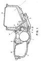
- Figure 1 is a sectional view of the process cartridge in the first embodiment of the present invention, depicting the structure thereof.
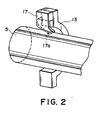
- Figure 2 is a perspective view of the magnetic seal portion in the first embodiment of the present invention.
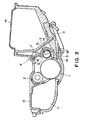
- Figure 3 is a sectional view of the process cartridge in the second embodiment of the present invention, depicting the structure thereof.
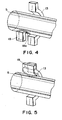
- Figure 4 is a perspective view of the magnetic seal portion in the second embodiment of the present invention.
- Figure 5 is a perspective view of the magnetic seal portion in the third embodiment of the present invention.
- Figure 6 is a sectional view of the seal portion of the developing deice in a conventional process cartridge, depicting the essential structure thereof.
- Figure 7 is a longitudinal sectional view of the seal portion of the developing device in the conventional process cartridge, depicting the essential structure thereof.
- Figure 8 is a sectional view of the seal portion of the developing device employing a magnetic sealing member, depicting the essential structure thereof.
- Figures 1 and 2 depicts the first embodiment of the present invention.
- Figure 1 is a sectional view of a process cartridge comprising a developing apparatus
- Figure 2 is an enlarged perspective view of the principal portion of the sealing portion in the developing apparatus.
- the process cartridge comprises an image bearing member and at least one processing means.
- the processing means there are a charging means for charging the surface of an image bearing member, a developing means for forming a toner image on an image bearing member, a cleaning means for removing the toner remaining on an image bearing member, and the like.
- the process cartridge in this embodiment is removably installable in the main assembly of an image forming apparatus, and comprises an electrophotographic photosensitive member 1 as an image bearing member, a charging means 2, a toner container 3 as a developing container, a developing sleeve 5 as a developer carrier member, a developing means 4 comprising a development blade 7 or the like, and a cleaning means 11.
- These components are integrally disposed in a process cartridge housing in such a manner that the photosensitive member 1 is surrounded by the rest.
- the toner container 3 holds single component magnetic toner (developer) which contains magnetic particles.
- the housing is constituted of frames 15 and 16.
- the developing sleeve 5 contains a magnetic roller 6, and is disposed in the toner container 3, being rotatively supported by a sleeve bearing (unillustrated) fixed to the toner container 3.
- the toner fed out of the toner container 3 is adhered to the surface of the developing sleeve 5 by the magnetic force of the magnetic roller 6, forming a toner layer.
- the toner layer is regulated by the development blade 7 to give it a predetermined thickness, and then is conveyed to a point where the distance of the toner layer to the latent image on the photosensitive drum 1 as an image bearing member becomes shortest. At this point, the toner particles is the toner layer are adhere to the latent image; in other words, the latent image is developed.
- the developing means 4 is provided with a magnet 13 as a magnetic sealing member, which is disposed at each longitudinal end of the developing sleeve 5, being attached to the toner container 3 in such a manner that a predetermined gap g is formed between the peripheral surface of the developing sleeve 5 and itself.
- a magnetic member 14 of magnetic metal is disposed across the thickness of the sleeve from the magnet 13.
- the process cartridge in this embodiment also comprises a toner guide member 17 formed of elastic material.
- the guide member 17 is disposed in contact with the surface of the developing sleeve 5, on the upstream side of the area where the latent image on the photosensitive drum 1 is developed, that is, adjacent to the exit side g1 of the gap g in which the magnetic seal is formed.
- the guide member 17 is located at the same position as the magnet 13, in terms of the longitudinal direction of the developing sleeve 5, and diagonally extends toward the developing sleeve 5 against the rotational direction of the developing sleeve 5.
- the guide member 17 is counterdirectionally contacted to the developing sleeve with respect to the direction of movement of the surface of the developing sleeve 5.
- the free end 17a of the guide member 17 is inclined (non-parallel with the movement direction of the surface of the developing sleeve 5) so that the inner (in the longitudinal direction) part thereof is downstream with respect to the movement direction of the surface of the developing sleeve.
- Figures 3 and 4 depict another embodiment of the present invention.
- Figure 3 is a sectional view of a process cartridge
- Figure 4 is an enlarged perspective view of the essential portion of the sealing portion in the process cartridge.
- a guide member 18 is disposed adjacent to the entrance side g2 of the gap g.
- the position of the guide member 18 in terms of the longitudinal direction of the developing sleeve 5 is the same as the position of the magnet 13 as the position of the guide member 17 in terms of the longitudinal direction of the developing sleeve 5 is the same as the position of the magnet 13 in the first embodiment.
- the guide member 18 diagonally extends in the same direction as the rotational direction of the developing sleeve 5, and contacts the surface of the developing sleeve 5, on the side which faces the photosensitive drum 1, by the tip portion 18a.
- the tip portion 18a is tapered in such a manner that as the toner adheres to the surface of the developing sleeve 5, on the area correspondent to the magnetic seal, and reaches the guide member 18, it is scraped by the tip portion 18a, and then is guided by the same in the longitudinally inward direction of the developing sleeve 5.
- This arrangement can also prevents the developer from accumulating at the entrance side g2 of the gap g, and eventually seeping out of the developing apparatus.
- Figure 5 depicts the third embodiment of the present invention.
- the edges of the guide member 19 in the longitudinal direction of the developing sleeve 5 extend beyond the corresponding edges of the-magnet 13. Therefore, the toner, which adheres to the developing sleeve 5, in the magnetic seal area, and comes out to the side which faces the photosensitive member 1, can be more reliably scraped, and guided in the longitudinally inward direction of the developing sleeve 5, by the guide member 19. In other words, it is possible to prevent more reliably the toner from accumulating at the entrance side g2 of the gap g.
- a piece of magnetic metal is disposed within the developing sleeve 5, and the sealing member 13 is a magnet.
- the positional relationship between the magnetic metal and a magnet may be reversed; a piece of magnet may disposed in the developing sleeve 5, and the sealing member 13 may be made of magnetic metal. Further, both components may be constituted of a piece of magnet.
- a magnetic roller for holding magnetic developer on the surface of a developing sleeve be placed in the developing sleeve in such a manner that the magnetic flux of the magnetic field generated by the magnetic roller and a magnetic seal is substantially concentrated in a gap formed between the magnet roller and the magnetic seal.
Landscapes
- Physics & Mathematics (AREA)
- General Physics & Mathematics (AREA)
- Dry Development In Electrophotography (AREA)
- Electrophotography Configuration And Component (AREA)
- Magnetic Brush Developing In Electrophotography (AREA)
Description
- The present invention relates to a developing apparatus which developing an electrostatic image on an image bearing member. In particular, it relates to a developing apparatus in which a focused magnetic field is used to seal the end portions of the developing device.
- In an electrophotographic image forming apparatus such as a printer or a copy machine, a latent image is formed by exposing the selected surface areas of an image bearing member having been uniformly charged, and the thus formed latent image is visualized as a toner image as it is developed with the toner borne on a developer carrier member. Then, the toner image is transferred onto a recording medium to complete a print.
- A developing apparatus for developing a latent image is provided with sealing members for preventing developer (toner) from seeping out of the developing apparatus. They are located at both longitudinal end of a developer carrying rotary member (developing sleeve. In the past, elastic material such as felt or foamed rubber has been widely used as the material for the sealing member. Such as in US-A-5267007 wherein an elastic sealing ring surrounds the developer roller shaft outboard of a magnetic seal. A typical usage of such elastic sealing material is illustrated in Figures 6 and 7. Figure 6 is a section of the essential structure of the sealing member in a conventional developing apparatus, and Figure 7 is a longitudinal section of the structure of the same.
- Referring to Figure 6, a developing
sleeve 5 as a developer carrier member contains amagnetic roller 6, and is disposed in atoner container 3 as a developer container, being rotatively supported by a sleeve bearing 12 fixed to thetoner container 3, as illustrated in Figure 7. Thus, the toner supplied from thetoner container 3 is adhered to the surface of the developingsleeve 5 by the magnetic force of themagnetic roller 6, and form a layer of toner. As the developingsleeve 5 is rotated, the thickness of the toner layer is regulated by adevelopment blade 7 so that it becomes a predetermined one. As the developingsleeve 5 is further rotated, the adhered toner is conveyed to a point where the distance between a latent image on a photosensitive drum 1 and the layer of the adhered toner on the developingsleeve 5 becomes shortest, and at this point, the toner adheres to the latent image, developing it. Both longitudinal ends of the developingsleeve 5 are fitted in anelastic sealing member 8. Theelastic sealing member 8 is attached to thetoner container 3, being positioned substantially behind the developingsleeve 5 as seen from the direction of the photosensitive member 1. As thiselastic sealing member 8 is pressed upon the peripheral surface of the developingsleeve 5, toner is prevented from seeping out of the developing apparatus. - However, the above structure also has problems. For example, the
elastic sealing member 8 generates large load as it is pressed upon the peripheral surface of the developingsleeve 5. Further, theelastic sealing member 8 deteriorates through its contact with the developingsleeve 5, losing its ability to seal. In addition, the toner sometimes enters between the developingsleeve 5 and theelastic sealing member 8. Though the amount of the toner which enters between the two components is very small, it is enough to increase or fluctuate the torque necessary to rotate the developing sleeve. The torque fluctuation disturbs the rotational speed of the developingsleeve 5, which has ill effects on image formation. - Therefore, a method for solving the above described problems has been proposed. According to this method, in order to prevent toner from seeping out, a magnetic sealing members is disposed at both longitudinal ends of the developing
sleeve 5, in a manner to create a predetermined gap between the developingsleeve 5 and itself. - Figure 8 is a sectional view of a developing apparatus employing a sealing
member 9 of magnetic material, depicting the structure thereof. Themagnetic sealing member 9 is disposed at each longitudinal end of the developingsleeve 5, being attached to thetoner container 3 in a manner to hold a predetermined gap g between the peripheral surface of the developingsleeve 5 and itself. The developingsleeve 5 contains amagnet 10, generating a magnetic field whose magnetic flux concentrates between themagnetic sealing member 9 and the magnetic poles of themagnet 10. This concentration of magnetic flux forms the toner in the gap g1, into a magnetic brush of toner. As a result, toner is prevented from seeping or leaking out of the developing area. - In Figure 8, the
magnetic sealing member 9 is formed of magnetic metal, and themagnet 10 is contained in the developingsleeve 5, but instead, the members designated by thereference numerals - As described above, when a magnetic field is used as a sealing means, the gap between the developing
sleeve 5 and themagnetic sealing member 9 can be sealed without physical contact between them. Therefore, the torque necessary to rotate the developingsleeve 5 can be reduced, which warrants usage of a small and inexpensive motor for driving the developingsleeve 5. Further, the fluctuation of the torque necessary to drive the developingsleeve 5 is also reduced; therefore, the rotational speeds of the developingsleeve 5 and the photosensitive drum 1 are not liable to fluctuate as much as when the contact type sealing member is employed. As a result, image quality deterioration traceable to the rotational speed fluctuation of the developingsleeve 5 and photosensitive member 1 can be eliminated. In addition, since there is no friction between themagnetic sealing member 9 and the developingsleeve 5, themagnetic sealing member 9 can be semipermanently used; it can be simply recycled. Since the method employing a magnetic sealing member is a method in which toner is held by magnetic force in the gap g formed between the developingsleeve 5 and themagnetic sealing member 9, it is necessary to increase the density of the magnetic flux in the gap g in order to increase the toner sealing performance. For example, in the case of a process cartridge removable installable in the main assembly of an image forming apparatus, the cartridge is installed or removed by a user; therefore, the vibrations or the shocks are generated as the cartridge is handled by the user, and these vibrations and shocks are liable to cause toner leakage. Thus, the magnetic force of themagnets - Also, in the case of the structure employing a magnetic seal, as the developing
sleeve 5 rotates, a portion of the toner within the gap g adheres to the surface of the developingsleeve 5, forming a toner layer thereon, and comes out of the exit side g1 of the gap g. This portion of the toner re-enters the gap g from the entrance side g2 of the gap g, as the developingsleeve 5 rotates. However, when the magnetic flux density is high, this portion of the toner is liable to accumulate at the entrance side g2 of the gap g, and eventually seeps out of the developing apparatus, as the developing operation is repeated. - A primary object of the present invention is to provide a developing apparatus employing a magnetic seal.
- Another object of the present invention is to provide a developing apparatus which does not collect developer at the end portion of the magnetic seal, and also does not leak developer.
- According to an aspect of the present invention, there is provided a developing apparatus comprising a container, having an opening, for containing magnetic developer; a developer carrying member, rotatably disposed in the opening, for carrying the magnetic developer; a magnetic sealing member disposed spaced from a peripheral surface of the developer carrying member; and a guiding member for guiding the developer inwardly in a longitudinal direction of the developer carrying member, the guiding member being disposed adjacent an end, in a peripheral direction of the developer carrying member, of the magnetic sealing member.
- These and other objects, features and advantages of the present invention will become more apparent upon a consideration of the following description of the preferred embodiments of the present invention taken in conjunction with the accompanying drawings.
- Figure 1 is a sectional view of the process cartridge in the first embodiment of the present invention, depicting the structure thereof.
- Figure 2 is a perspective view of the magnetic seal portion in the first embodiment of the present invention.
- Figure 3 is a sectional view of the process cartridge in the second embodiment of the present invention, depicting the structure thereof.
- Figure 4 is a perspective view of the magnetic seal portion in the second embodiment of the present invention.
- Figure 5 is a perspective view of the magnetic seal portion in the third embodiment of the present invention.
- Figure 6 is a sectional view of the seal portion of the developing deice in a conventional process cartridge, depicting the essential structure thereof.
- Figure 7 is a longitudinal sectional view of the seal portion of the developing device in the conventional process cartridge, depicting the essential structure thereof.
- Figure 8 is a sectional view of the seal portion of the developing device employing a magnetic sealing member, depicting the essential structure thereof.
- Hereinafter, preferable embodiments of the present invention will be described with reference to the drawings.
- Figures 1 and 2 depicts the first embodiment of the present invention. Figure 1 is a sectional view of a process cartridge comprising a developing apparatus, and Figure 2 is an enlarged perspective view of the principal portion of the sealing portion in the developing apparatus.
- The process cartridge comprises an image bearing member and at least one processing means. As for the processing means, there are a charging means for charging the surface of an image bearing member, a developing means for forming a toner image on an image bearing member, a cleaning means for removing the toner remaining on an image bearing member, and the like.
- Referring to Figure 1, the process cartridge in this embodiment is removably installable in the main assembly of an image forming apparatus, and comprises an electrophotographic photosensitive member 1 as an image bearing member, a charging means 2, a
toner container 3 as a developing container, a developingsleeve 5 as a developer carrier member, a developingmeans 4 comprising adevelopment blade 7 or the like, and a cleaning means 11. These components are integrally disposed in a process cartridge housing in such a manner that the photosensitive member 1 is surrounded by the rest. Thetoner container 3 holds single component magnetic toner (developer) which contains magnetic particles. The housing is constituted offrames - The developing
sleeve 5 contains amagnetic roller 6, and is disposed in thetoner container 3, being rotatively supported by a sleeve bearing (unillustrated) fixed to thetoner container 3. The toner fed out of thetoner container 3 is adhered to the surface of the developingsleeve 5 by the magnetic force of themagnetic roller 6, forming a toner layer. As the developingsleeve 5 rotates, the toner layer is regulated by thedevelopment blade 7 to give it a predetermined thickness, and then is conveyed to a point where the distance of the toner layer to the latent image on the photosensitive drum 1 as an image bearing member becomes shortest. At this point, the toner particles is the toner layer are adhere to the latent image; in other words, the latent image is developed. - The developing means 4 is provided with a
magnet 13 as a magnetic sealing member, which is disposed at each longitudinal end of the developingsleeve 5, being attached to thetoner container 3 in such a manner that a predetermined gap g is formed between the peripheral surface of the developingsleeve 5 and itself. In the developingsleeve 5, amagnetic member 14 of magnetic metal is disposed across the thickness of the sleeve from themagnet 13. With this arrangement, a concentrated magnetic field is formed between themagnet 13, and a magnetic pole of themagnetic member 14 enveloped in the developingsleeve 5, wherein the toner in the gap g is formed into a magnetic brush, thus preventing the inside toner from leaking out of the development area. - The process cartridge in this embodiment also comprises a
toner guide member 17 formed of elastic material. Theguide member 17 is disposed in contact with the surface of the developingsleeve 5, on the upstream side of the area where the latent image on the photosensitive drum 1 is developed, that is, adjacent to the exit side g1 of the gap g in which the magnetic seal is formed. Theguide member 17 is located at the same position as themagnet 13, in terms of the longitudinal direction of the developingsleeve 5, and diagonally extends toward the developingsleeve 5 against the rotational direction of the developingsleeve 5. Theguide member 17 is counterdirectionally contacted to the developing sleeve with respect to the direction of movement of the surface of the developingsleeve 5. The free end 17a of theguide member 17 is inclined (non-parallel with the movement direction of the surface of the developing sleeve 5) so that the inner (in the longitudinal direction) part thereof is downstream with respect to the movement direction of the surface of the developing sleeve. With this arrangement, as the developingsleeve 5 rotates, theguide member 17 scrapes the toner on the surface of the developingsleeve 5, and the inclined end surface thereof guides it in the longitudinally inward direction of the developingsleeve 5, preventing a portion of the magnetic brush (toner) from being carried from the exit side g1 to the entrance side g2, and accumulated at the entrance side g2. Therefore, the magnetic force of the magnetic seal may be increased to keep toner more effectively sealed while the cartridge is handled by a user, as well as while it is in operation. - Further, even though the
guide member 17 is in contact with the developingsleeve 5, there is practically no need for torque increase, since the contact area is very small. Therefore, one of the desirable effects of the employment of a magnetic seal, that is, reduced torque requirement, is not canceled by the employment of theguide member 17. - Figures 3 and 4 depict another embodiment of the present invention. Figure 3 is a sectional view of a process cartridge, and Figure 4 is an enlarged perspective view of the essential portion of the sealing portion in the process cartridge.
- In this second embodiment, a
guide member 18 is disposed adjacent to the entrance side g2 of the gap g. Referring to Figure 4, the position of theguide member 18 in terms of the longitudinal direction of the developingsleeve 5 is the same as the position of themagnet 13 as the position of theguide member 17 in terms of the longitudinal direction of the developingsleeve 5 is the same as the position of themagnet 13 in the first embodiment. However, contrary to the way theguide member 17 in the first embodiment diagonally extends against the rotational direction of the developingsleeve 5, theguide member 18 diagonally extends in the same direction as the rotational direction of the developingsleeve 5, and contacts the surface of the developingsleeve 5, on the side which faces the photosensitive drum 1, by thetip portion 18a. Thetip portion 18a is tapered in such a manner that as the toner adheres to the surface of the developingsleeve 5, on the area correspondent to the magnetic seal, and reaches theguide member 18, it is scraped by thetip portion 18a, and then is guided by the same in the longitudinally inward direction of the developingsleeve 5. This arrangement can also prevents the developer from accumulating at the entrance side g2 of the gap g, and eventually seeping out of the developing apparatus. - Figure 5 depicts the third embodiment of the present invention. In this embodiment, the edges of the
guide member 19 in the longitudinal direction of the developingsleeve 5 extend beyond the corresponding edges of the-magnet 13. Therefore, the toner, which adheres to the developingsleeve 5, in the magnetic seal area, and comes out to the side which faces the photosensitive member 1, can be more reliably scraped, and guided in the longitudinally inward direction of the developingsleeve 5, by theguide member 19. In other words, it is possible to prevent more reliably the toner from accumulating at the entrance side g2 of the gap g. - In the preceding embodiments, a piece of magnetic metal is disposed within the developing
sleeve 5, and the sealingmember 13 is a magnet. However, the positional relationship between the magnetic metal and a magnet may be reversed; a piece of magnet may disposed in the developingsleeve 5, and the sealingmember 13 may be made of magnetic metal. Further, both components may be constituted of a piece of magnet. - Here, a magnetic roller for holding magnetic developer on the surface of a developing sleeve be placed in the developing sleeve in such a manner that the magnetic flux of the magnetic field generated by the magnetic roller and a magnetic seal is substantially concentrated in a gap formed between the magnet roller and the magnetic seal.
- While the invention has been described with reference to the structures disclosed herein, it is not confined to the details set forth and this application is intended to cover such modifications or changes as may come within the scope of the following claims.
Claims (10)
- A developing apparatus comprising:characterised by comprising a guiding member (17, 18, 19) for guiding the developer inwardly in a longitudinal direction of said developer carrier member (5), said guiding member (17,18,19) being disposed adjacent said end surface of said magnetic sealing member (13) in the circumferential direction of said developer carrier member (15).a container (3), for containing magnetic developer having an opening;a developer carrier member (5), rotatably disposed in the opening, for carrying the magnetic developer; anda magnetic sealing member (13) disposed spaced from a peripheral surface of said developer carrier member (5) and having an end surface facing in a circumferential direction of said developer carrier member (5);
- An apparatus according to claim 1, wherein said magnetic developer is toner, and said magnetic sealing member (13) includes a magnet for forming a concentrated magnetic field.
- An apparatus according to claim 1 or claim 2, wherein said guiding member (17, 18, 19) has an end face (17a) which is inclined and contacted to the peripheral surface of said developer carrier member (5).
- An apparatus according to claim 3, wherein the end face (17a) of the guiding member (17, 18, 19) is inclined obliquely relative to the circumferential direction of said developer carrying member (5), and said end face (17a) of said guiding member (17,18,19), faces upstream relative to the movement direction of the developer carrier member (5), and towards the central region of said developer carrier member (5).
- An apparatus according to any preceding claim, wherein said guiding member (17, 18, 19) is disposed adjacent a developer outlet portion (g1).
- An apparatus according to any of claims 1 to 4, wherein said guiding member (17, 18, 19) is disposed adjacent a developer returning portion (g2).
- An apparatus according to any preceding claim, wherein a guiding portion of said guiding member (17, 18, 19) is disposed between said magnetic sealing member (13) and said developer carrier member (5).
- An apparatus according to any preceding claim, wherein said guiding member (17, 18, 19) is extended beyond said magnetic sealing member (13) in a longitudinal direction of said developer carrier member.
- An apparatus according to any preceding claim, wherein the developing apparatus forms part of a cartridge which includes an image bearer member (1) for bearing an electrostatic image, and said cartridge is detachably mountable to a main assembly of an image forming apparatus.
- A process cartridge including a development apparatus according to any of claims 1 to 8.
Applications Claiming Priority (3)
| Application Number | Priority Date | Filing Date | Title |
|---|---|---|---|
| JP4694496 | 1996-02-09 | ||
| JP04694496A JP3372747B2 (en) | 1996-02-09 | 1996-02-09 | Developing device |
| JP46944/96 | 1996-02-09 |
Publications (3)
| Publication Number | Publication Date |
|---|---|
| EP0789286A2 EP0789286A2 (en) | 1997-08-13 |
| EP0789286A3 EP0789286A3 (en) | 1998-11-18 |
| EP0789286B1 true EP0789286B1 (en) | 2003-04-23 |
Family
ID=12761419
Family Applications (1)
| Application Number | Title | Priority Date | Filing Date |
|---|---|---|---|
| EP97300761A Expired - Lifetime EP0789286B1 (en) | 1996-02-09 | 1997-02-06 | Developing apparatus |
Country Status (6)
| Country | Link |
|---|---|
| US (1) | US5790923A (en) |
| EP (1) | EP0789286B1 (en) |
| JP (1) | JP3372747B2 (en) |
| KR (1) | KR100210885B1 (en) |
| CN (1) | CN1082200C (en) |
| DE (1) | DE69721098T2 (en) |
Cited By (1)
| Publication number | Priority date | Publication date | Assignee | Title |
|---|---|---|---|---|
| US9081331B2 (en) | 2013-08-13 | 2015-07-14 | Kyocera Document Solutions Inc. | Developing device and image forming apparatus |
Families Citing this family (65)
| Publication number | Priority date | Publication date | Assignee | Title |
|---|---|---|---|---|
| JPH10288887A (en) * | 1997-04-16 | 1998-10-27 | Canon Inc | Developing device and process cartridge |
| JP3927661B2 (en) * | 1997-09-12 | 2007-06-13 | キヤノン株式会社 | Developing device, process cartridge, and image forming apparatus |
| JP3466888B2 (en) * | 1997-10-01 | 2003-11-17 | キヤノン株式会社 | Process cartridge and electrophotographic image forming apparatus |
| JP3472108B2 (en) * | 1997-10-01 | 2003-12-02 | キヤノン株式会社 | Process cartridge and electrophotographic image forming apparatus |
| JP3437424B2 (en) * | 1997-10-27 | 2003-08-18 | キヤノン株式会社 | Developing device, process cartridge, and electrophotographic image forming device |
| JP4018210B2 (en) * | 1997-10-29 | 2007-12-05 | キヤノン株式会社 | Developing device, process cartridge, and electrophotographic image forming apparatus |
| JP3542473B2 (en) * | 1997-10-30 | 2004-07-14 | キヤノン株式会社 | Developing device, process cartridge and image forming device |
| JPH11143226A (en) * | 1997-11-11 | 1999-05-28 | Canon Inc | Process cartridge and developing device |
| JP4154020B2 (en) * | 1998-02-17 | 2008-09-24 | キヤノン株式会社 | Development device |
| JP2000056561A (en) * | 1998-08-04 | 2000-02-25 | Canon Inc | Developing device, process cartridge, and electrophotographic image forming device |
| JP2000089567A (en) * | 1998-09-11 | 2000-03-31 | Canon Inc | Shutter member, process cartridge, image forming apparatus |
| JP2000194248A (en) | 1998-12-28 | 2000-07-14 | Canon Inc | Process cartridge and charging unit and developing unit |
| DE69929667T2 (en) * | 1998-12-28 | 2006-08-10 | Canon K.K. | Image developer, work unit, electrophotographic image forming apparatus and development frame unit |
| JP3768706B2 (en) | 1998-12-28 | 2006-04-19 | キヤノン株式会社 | Electrophotographic image forming apparatus |
| JP3679645B2 (en) | 1999-03-29 | 2005-08-03 | キヤノン株式会社 | Process cartridge |
| JP3363873B2 (en) | 1999-07-13 | 2003-01-08 | キヤノン株式会社 | Method for sequentially displaying developer amount and electrophotographic image forming apparatus |
| JP2001051490A (en) | 1999-08-06 | 2001-02-23 | Canon Inc | Developing device, process cartridge, and electrophotographic image forming device |
| JP3943772B2 (en) | 1999-08-06 | 2007-07-11 | キヤノン株式会社 | Developing device, process cartridge, and electrophotographic image forming apparatus |
| EP1347346B1 (en) * | 1999-08-23 | 2014-04-23 | Brother Kogyo Kabushiki Kaisha | Developing device, process cartridge, and image forming apparatus |
| JP2001092335A (en) | 1999-09-17 | 2001-04-06 | Canon Inc | Process cartridge, electrophotographic image forming apparatus, and developer amount detecting member |
| JP3679665B2 (en) | 1999-11-19 | 2005-08-03 | キヤノン株式会社 | Gap assurance member, developing device, charging device, and process cartridge |
| JP3478797B2 (en) | 1999-12-28 | 2003-12-15 | キヤノン株式会社 | Process cartridge and electrophotographic image forming apparatus |
| JP2001255786A (en) | 2000-01-07 | 2001-09-21 | Canon Inc | Electrophotographic image forming device |
| JP3745231B2 (en) | 2000-01-13 | 2006-02-15 | キヤノン株式会社 | Process cartridge and electrophotographic image forming apparatus |
| JP4474002B2 (en) * | 2000-02-04 | 2010-06-02 | キヤノン株式会社 | Developing device, process cartridge, and image forming apparatus |
| JP4250294B2 (en) | 2000-02-16 | 2009-04-08 | キヤノン株式会社 | Color electrophotographic image forming apparatus and process cartridge |
| JP2001290355A (en) | 2000-04-06 | 2001-10-19 | Canon Inc | Developing device, process cartridge, and electrophotographic image forming device |
| US6697578B2 (en) | 2000-08-25 | 2004-02-24 | Canon Kabushiki Kaisha | Memory member, unit, process cartridge and electrophotographic image forming apparatus |
| JP3432218B2 (en) | 2000-10-31 | 2003-08-04 | キヤノン株式会社 | Process cartridge, load generating member, and electrophotographic image forming apparatus |
| JP2002196647A (en) | 2000-12-22 | 2002-07-12 | Canon Inc | Process cartridge and image forming apparatus |
| JP4745511B2 (en) * | 2001-02-09 | 2011-08-10 | キヤノン株式会社 | Image forming apparatus and process cartridge |
| JP2002258720A (en) | 2001-03-05 | 2002-09-11 | Canon Inc | Electrophotographic image forming apparatus and process cartridge |
| JP4819232B2 (en) | 2001-03-09 | 2011-11-24 | キヤノン株式会社 | Process cartridge and image forming apparatus provided with the same |
| JP4310069B2 (en) | 2001-04-27 | 2009-08-05 | キヤノン株式会社 | Developing device having magnetic seal |
| JP3969990B2 (en) | 2001-10-10 | 2007-09-05 | キヤノン株式会社 | Developing device, process cartridge, and image forming apparatus |
| JP2003228234A (en) * | 2002-02-01 | 2003-08-15 | Canon Inc | Process cartridge and image forming apparatus |
| JP3907496B2 (en) | 2002-02-27 | 2007-04-18 | キヤノン株式会社 | Developing device, process cartridge, electrophotographic image forming apparatus, developer container and method of assembling the same |
| JP2003255806A (en) | 2002-02-28 | 2003-09-10 | Canon Inc | Process cartridge, developing device and image forming device |
| JP4072362B2 (en) | 2002-03-14 | 2008-04-09 | キヤノン株式会社 | Developing device, process cartridge, and image forming apparatus |
| US6760555B2 (en) * | 2002-03-21 | 2004-07-06 | Hewlett-Packard Development Company, L.P. | System for and method of toner flow control |
| JP3854897B2 (en) * | 2002-05-21 | 2006-12-06 | キヤノン株式会社 | Developing device, process cartridge, and image forming apparatus |
| JP2004101690A (en) * | 2002-09-06 | 2004-04-02 | Canon Inc | Developing device, process cartridge, and electrophotographic image forming device |
| JP4314006B2 (en) * | 2002-09-30 | 2009-08-12 | キヤノン株式会社 | Image forming apparatus |
| JP3913153B2 (en) * | 2002-09-30 | 2007-05-09 | キヤノン株式会社 | Power supply contact member, process cartridge, and image forming apparatus |
| US6980755B2 (en) * | 2002-09-30 | 2005-12-27 | Canon Kabushiki Kaisha | Recycling method for developer supplying unit including the step of driving a feeding member in a direction to feed developer from a developer supply port to a developer accommodating portion |
| JP2004144803A (en) | 2002-10-22 | 2004-05-20 | Canon Inc | Developing device and process cartridge |
| JP4261872B2 (en) * | 2002-10-29 | 2009-04-30 | キヤノン株式会社 | Development device |
| JP4366067B2 (en) * | 2002-11-07 | 2009-11-18 | キヤノン株式会社 | Developing device, process cartridge, and image forming apparatus |
| JP3548564B2 (en) * | 2002-11-08 | 2004-07-28 | キヤノン株式会社 | Developing roller assembly method |
| JP4217474B2 (en) * | 2002-12-20 | 2009-02-04 | キヤノン株式会社 | Magnetic seal member, developing device using the same, process cartridge, and electrophotographic image forming apparatus |
| JP2004205950A (en) * | 2002-12-26 | 2004-07-22 | Canon Inc | Cleaning device, process cartridge and image forming device |
| US7158749B2 (en) * | 2004-04-26 | 2007-01-02 | Canon Kabushiki Kaisha | Cleaning device, process cartridge, cleaning member and electrophotographic image forming apparatus |
| JP4185927B2 (en) * | 2004-09-29 | 2008-11-26 | キヤノン株式会社 | Developing device, process cartridge, and image forming apparatus |
| CN100429583C (en) * | 2004-09-29 | 2008-10-29 | 佳能株式会社 | Developing device, process cartridge, and image forming apparatus |
| JP3950882B2 (en) * | 2004-10-06 | 2007-08-01 | キヤノン株式会社 | Electrophotographic image forming apparatus |
| JP4726530B2 (en) * | 2005-04-21 | 2011-07-20 | 京セラミタ株式会社 | DEVELOPING DEVICE HAVING MAGNETIC SEAL AND IMAGE FORMING DEVICE HAVING THE DEVELOPING DEVICE |
| JP4280770B2 (en) * | 2006-01-11 | 2009-06-17 | キヤノン株式会社 | Process cartridge and electrophotographic image forming apparatus |
| JP4448122B2 (en) | 2006-11-15 | 2010-04-07 | キヤノン株式会社 | Developing device and process cartridge |
| JP4458378B2 (en) | 2007-06-29 | 2010-04-28 | キヤノン株式会社 | Process cartridge and electrophotographic image forming apparatus |
| JP4458377B2 (en) | 2007-06-29 | 2010-04-28 | キヤノン株式会社 | Process cartridge and electrophotographic image forming apparatus |
| WO2011074707A1 (en) | 2009-12-16 | 2011-06-23 | キヤノン株式会社 | Process cartridge, photosensitive drum unit, developing unit, and xerographic image forming device |
| JP5569803B2 (en) * | 2010-09-10 | 2014-08-13 | 株式会社リコー | Developing device and image forming apparatus |
| US9377715B2 (en) * | 2012-12-20 | 2016-06-28 | Canon Kabushiki Kaisha | Developing unit and process cartridge |
| US9535398B2 (en) | 2014-09-04 | 2017-01-03 | Canon Kabushiki Kaisha | Developer cartridge, developing apparatus, process cartridge and image forming apparatus |
| US10969730B2 (en) | 2019-02-25 | 2021-04-06 | Canon Kabushiki Kaisha | Image forming apparatus and image forming unit |
Family Cites Families (16)
| Publication number | Priority date | Publication date | Assignee | Title |
|---|---|---|---|---|
| JPS61175663A (en) * | 1985-01-30 | 1986-08-07 | Canon Inc | developing device |
| DE69033384T2 (en) * | 1989-03-31 | 2000-05-11 | Canon K.K., Tokio/Tokyo | Processor |
| JP2646393B2 (en) * | 1989-05-31 | 1997-08-27 | キヤノン株式会社 | Developing device |
| JP2892456B2 (en) * | 1989-08-04 | 1999-05-17 | キヤノン株式会社 | Developing device |
| JP2899079B2 (en) * | 1990-07-10 | 1999-06-02 | キヤノン株式会社 | Developing device |
| JPH04136965A (en) * | 1990-09-28 | 1992-05-11 | Canon Inc | Developing device |
| US5294960A (en) * | 1990-11-06 | 1994-03-15 | Canon Kabushiki Kaisha | Detachable two-frame process cartridge for an image forming apparatus |
| US5475467A (en) * | 1993-04-19 | 1995-12-12 | Canon Kabushiki Kaisha | Sealing member, and process cartridge and image forming apparatus using same |
| JP3086371B2 (en) * | 1993-12-29 | 2000-09-11 | キヤノン株式会社 | Process cartridge and developing device |
| US5450169A (en) * | 1994-06-23 | 1995-09-12 | Xerox Corporation | Multi-lobe magnetic seals |
| JP3074114B2 (en) * | 1994-07-12 | 2000-08-07 | キヤノン株式会社 | Developing device and process cartridge |
| JPH08137259A (en) * | 1994-11-04 | 1996-05-31 | Fuji Xerox Co Ltd | Developing device |
| JPH08137258A (en) * | 1994-11-07 | 1996-05-31 | Fuji Xerox Co Ltd | Developing device |
| US5552864A (en) * | 1995-01-17 | 1996-09-03 | Xerox Corporation | Magnetic seal with tapered shunts |
| JPH08202152A (en) * | 1995-01-24 | 1996-08-09 | Canon Inc | Development device |
| JPH08202153A (en) * | 1995-01-31 | 1996-08-09 | Canon Inc | Development device |
-
1996
- 1996-02-09 JP JP04694496A patent/JP3372747B2/en not_active Expired - Fee Related
-
1997
- 1997-02-05 CN CN97104865A patent/CN1082200C/en not_active Expired - Fee Related
- 1997-02-06 EP EP97300761A patent/EP0789286B1/en not_active Expired - Lifetime
- 1997-02-06 KR KR1019970003813A patent/KR100210885B1/en not_active Expired - Fee Related
- 1997-02-06 DE DE69721098T patent/DE69721098T2/en not_active Expired - Lifetime
- 1997-02-06 US US08/797,468 patent/US5790923A/en not_active Expired - Lifetime
Cited By (1)
| Publication number | Priority date | Publication date | Assignee | Title |
|---|---|---|---|---|
| US9081331B2 (en) | 2013-08-13 | 2015-07-14 | Kyocera Document Solutions Inc. | Developing device and image forming apparatus |
Also Published As
| Publication number | Publication date |
|---|---|
| KR970062825A (en) | 1997-09-12 |
| DE69721098T2 (en) | 2003-12-18 |
| CN1162773A (en) | 1997-10-22 |
| KR100210885B1 (en) | 1999-07-15 |
| JP3372747B2 (en) | 2003-02-04 |
| JPH09218578A (en) | 1997-08-19 |
| EP0789286A2 (en) | 1997-08-13 |
| US5790923A (en) | 1998-08-04 |
| CN1082200C (en) | 2002-04-03 |
| DE69721098D1 (en) | 2003-05-28 |
| EP0789286A3 (en) | 1998-11-18 |
Similar Documents
| Publication | Publication Date | Title |
|---|---|---|
| EP0789286B1 (en) | Developing apparatus | |
| KR0137120B1 (en) | Process units, developing equipment and cleaning equipment for electrophotographic and electrophotographic equipment | |
| US7418225B2 (en) | Developing apparatus, process cartridge, electrophotographic image forming apparatus and end portion regulating member | |
| US5182601A (en) | Image forming apparatus having toner handling units which are alternatively usable as a developing device or a cleaning device | |
| JPH08179618A (en) | Image forming device | |
| US7283765B2 (en) | Developing device, process cartridge, and image forming apparatus having developing-roller scraping member | |
| US6205304B1 (en) | Developing apparatus | |
| EP1494091B1 (en) | Magnetic seal for a developing apparatus | |
| US6044237A (en) | Developing apparatus | |
| JP4366067B2 (en) | Developing device, process cartridge, and image forming apparatus | |
| US6029030A (en) | Developing apparatus with magnetic seal | |
| JPH08137275A (en) | Image forming apparatus and process cartridge | |
| US6181898B1 (en) | Developing apparatus | |
| JP4261872B2 (en) | Development device | |
| JP3001760B2 (en) | Developing device and process cartridge | |
| JP3086371B2 (en) | Process cartridge and developing device | |
| JP3074114B2 (en) | Developing device and process cartridge | |
| KR100611988B1 (en) | Developing apparatus and image forming apparatus using the same | |
| JP3235697B2 (en) | Developing device and image forming apparatus using the same | |
| JP3387729B2 (en) | Process cartridge and developing device | |
| JP3972690B2 (en) | Development device | |
| JP7210293B2 (en) | cleaning device and cartridge | |
| JP4574284B2 (en) | Developing device and image forming apparatus having the same | |
| JPH08220879A (en) | Development device | |
| JP2005189749A (en) | Developing device, process cartridge, and image forming apparatus |
Legal Events
| Date | Code | Title | Description |
|---|---|---|---|
| PUAI | Public reference made under article 153(3) epc to a published international application that has entered the european phase |
Free format text: ORIGINAL CODE: 0009012 |
|
| AK | Designated contracting states |
Kind code of ref document: A2 Designated state(s): CH DE FR GB IT LI |
|
| PUAL | Search report despatched |
Free format text: ORIGINAL CODE: 0009013 |
|
| AK | Designated contracting states |
Kind code of ref document: A3 Designated state(s): CH DE FR GB IT LI |
|
| 17P | Request for examination filed |
Effective date: 19990331 |
|
| 17Q | First examination report despatched |
Effective date: 20010206 |
|
| GRAH | Despatch of communication of intention to grant a patent |
Free format text: ORIGINAL CODE: EPIDOS IGRA |
|
| GRAH | Despatch of communication of intention to grant a patent |
Free format text: ORIGINAL CODE: EPIDOS IGRA |
|
| GRAA | (expected) grant |
Free format text: ORIGINAL CODE: 0009210 |
|
| AK | Designated contracting states |
Designated state(s): CH DE FR GB IT LI |
|
| PG25 | Lapsed in a contracting state [announced via postgrant information from national office to epo] |
Ref country code: LI Free format text: LAPSE BECAUSE OF FAILURE TO SUBMIT A TRANSLATION OF THE DESCRIPTION OR TO PAY THE FEE WITHIN THE PRESCRIBED TIME-LIMIT Effective date: 20030423 Ref country code: IT Free format text: LAPSE BECAUSE OF FAILURE TO SUBMIT A TRANSLATION OF THE DESCRIPTION OR TO PAY THE FEE WITHIN THE PRESCRIBED TIME-LIMIT;WARNING: LAPSES OF ITALIAN PATENTS WITH EFFECTIVE DATE BEFORE 2007 MAY HAVE OCCURRED AT ANY TIME BEFORE 2007. THE CORRECT EFFECTIVE DATE MAY BE DIFFERENT FROM THE ONE RECORDED. Effective date: 20030423 Ref country code: CH Free format text: LAPSE BECAUSE OF FAILURE TO SUBMIT A TRANSLATION OF THE DESCRIPTION OR TO PAY THE FEE WITHIN THE PRESCRIBED TIME-LIMIT Effective date: 20030423 |
|
| REG | Reference to a national code |
Ref country code: GB Ref legal event code: FG4D |
|
| REG | Reference to a national code |
Ref country code: CH Ref legal event code: EP |
|
| REF | Corresponds to: |
Ref document number: 69721098 Country of ref document: DE Date of ref document: 20030528 Kind code of ref document: P |
|
| REG | Reference to a national code |
Ref country code: CH Ref legal event code: PL |
|
| ET | Fr: translation filed | ||
| PLBE | No opposition filed within time limit |
Free format text: ORIGINAL CODE: 0009261 |
|
| STAA | Information on the status of an ep patent application or granted ep patent |
Free format text: STATUS: NO OPPOSITION FILED WITHIN TIME LIMIT |
|
| 26N | No opposition filed |
Effective date: 20040126 |
|
| REG | Reference to a national code |
Ref country code: FR Ref legal event code: PLFP Year of fee payment: 19 |
|
| PGFP | Annual fee paid to national office [announced via postgrant information from national office to epo] |
Ref country code: DE Payment date: 20150228 Year of fee payment: 19 |
|
| PGFP | Annual fee paid to national office [announced via postgrant information from national office to epo] |
Ref country code: GB Payment date: 20150220 Year of fee payment: 19 Ref country code: FR Payment date: 20150227 Year of fee payment: 19 |
|
| REG | Reference to a national code |
Ref country code: DE Ref legal event code: R119 Ref document number: 69721098 Country of ref document: DE |
|
| GBPC | Gb: european patent ceased through non-payment of renewal fee |
Effective date: 20160206 |
|
| REG | Reference to a national code |
Ref country code: FR Ref legal event code: ST Effective date: 20161028 |
|
| PG25 | Lapsed in a contracting state [announced via postgrant information from national office to epo] |
Ref country code: FR Free format text: LAPSE BECAUSE OF NON-PAYMENT OF DUE FEES Effective date: 20160229 Ref country code: GB Free format text: LAPSE BECAUSE OF NON-PAYMENT OF DUE FEES Effective date: 20160206 Ref country code: DE Free format text: LAPSE BECAUSE OF NON-PAYMENT OF DUE FEES Effective date: 20160901 |