JP4745511B2 - Image forming apparatus and process cartridge - Google Patents
Image forming apparatus and process cartridge Download PDFInfo
- Publication number
- JP4745511B2 JP4745511B2 JP2001034155A JP2001034155A JP4745511B2 JP 4745511 B2 JP4745511 B2 JP 4745511B2 JP 2001034155 A JP2001034155 A JP 2001034155A JP 2001034155 A JP2001034155 A JP 2001034155A JP 4745511 B2 JP4745511 B2 JP 4745511B2
- Authority
- JP
- Japan
- Prior art keywords
- developer
- image
- carrying member
- carrier
- process cartridge
- Prior art date
- Legal status (The legal status is an assumption and is not a legal conclusion. Google has not performed a legal analysis and makes no representation as to the accuracy of the status listed.)
- Expired - Fee Related
Links
Images


Classifications
-
- G—PHYSICS
- G03—PHOTOGRAPHY; CINEMATOGRAPHY; ANALOGOUS TECHNIQUES USING WAVES OTHER THAN OPTICAL WAVES; ELECTROGRAPHY; HOLOGRAPHY
- G03G—ELECTROGRAPHY; ELECTROPHOTOGRAPHY; MAGNETOGRAPHY
- G03G21/00—Arrangements not provided for by groups G03G13/00 - G03G19/00, e.g. cleaning, elimination of residual charge
- G03G21/16—Mechanical means for facilitating the maintenance of the apparatus, e.g. modular arrangements
- G03G21/18—Mechanical means for facilitating the maintenance of the apparatus, e.g. modular arrangements using a processing cartridge, whereby the process cartridge comprises at least two image processing means in a single unit
- G03G21/1803—Arrangements or disposition of the complete process cartridge or parts thereof
- G03G21/1814—Details of parts of process cartridge, e.g. for charging, transfer, cleaning, developing
-
- G—PHYSICS
- G03—PHOTOGRAPHY; CINEMATOGRAPHY; ANALOGOUS TECHNIQUES USING WAVES OTHER THAN OPTICAL WAVES; ELECTROGRAPHY; HOLOGRAPHY
- G03G—ELECTROGRAPHY; ELECTROPHOTOGRAPHY; MAGNETOGRAPHY
- G03G15/00—Apparatus for electrographic processes using a charge pattern
- G03G15/06—Apparatus for electrographic processes using a charge pattern for developing
- G03G15/08—Apparatus for electrographic processes using a charge pattern for developing using a solid developer, e.g. powder developer
- G03G15/0806—Apparatus for electrographic processes using a charge pattern for developing using a solid developer, e.g. powder developer on a donor element, e.g. belt, roller
- G03G15/0813—Apparatus for electrographic processes using a charge pattern for developing using a solid developer, e.g. powder developer on a donor element, e.g. belt, roller characterised by means in the developing zone having an interaction with the image carrying member, e.g. distance holders
-
- G—PHYSICS
- G03—PHOTOGRAPHY; CINEMATOGRAPHY; ANALOGOUS TECHNIQUES USING WAVES OTHER THAN OPTICAL WAVES; ELECTROGRAPHY; HOLOGRAPHY
- G03G—ELECTROGRAPHY; ELECTROPHOTOGRAPHY; MAGNETOGRAPHY
- G03G15/00—Apparatus for electrographic processes using a charge pattern
- G03G15/06—Apparatus for electrographic processes using a charge pattern for developing
- G03G15/08—Apparatus for electrographic processes using a charge pattern for developing using a solid developer, e.g. powder developer
- G03G15/0806—Apparatus for electrographic processes using a charge pattern for developing using a solid developer, e.g. powder developer on a donor element, e.g. belt, roller
- G03G15/0817—Apparatus for electrographic processes using a charge pattern for developing using a solid developer, e.g. powder developer on a donor element, e.g. belt, roller characterised by the lateral sealing at both sides of the donor member with respect to the developer carrying direction
-
- G—PHYSICS
- G03—PHOTOGRAPHY; CINEMATOGRAPHY; ANALOGOUS TECHNIQUES USING WAVES OTHER THAN OPTICAL WAVES; ELECTROGRAPHY; HOLOGRAPHY
- G03G—ELECTROGRAPHY; ELECTROPHOTOGRAPHY; MAGNETOGRAPHY
- G03G2221/00—Processes not provided for by group G03G2215/00, e.g. cleaning or residual charge elimination
- G03G2221/16—Mechanical means for facilitating the maintenance of the apparatus, e.g. modular arrangements and complete machine concepts
- G03G2221/1648—Mechanical means for facilitating the maintenance of the apparatus, e.g. modular arrangements and complete machine concepts using seals, e.g. to prevent scattering of toner
-
- G—PHYSICS
- G03—PHOTOGRAPHY; CINEMATOGRAPHY; ANALOGOUS TECHNIQUES USING WAVES OTHER THAN OPTICAL WAVES; ELECTROGRAPHY; HOLOGRAPHY
- G03G—ELECTROGRAPHY; ELECTROPHOTOGRAPHY; MAGNETOGRAPHY
- G03G2221/00—Processes not provided for by group G03G2215/00, e.g. cleaning or residual charge elimination
- G03G2221/16—Mechanical means for facilitating the maintenance of the apparatus, e.g. modular arrangements and complete machine concepts
- G03G2221/18—Cartridge systems
- G03G2221/183—Process cartridge
Description
【0001】
【発明の属する技術分野】
本発明は、電子写真方式を利用して画像形成を行う複写機、プリンタ、ファクシミリ等の画像形成装置、及び感光ドラムと少なくとも現像手段とを一体的なカートリッジ構成とし、画像形成装置に対して着脱自在に装着されるプロセスカートリッジに関する。
【0002】
【従来の技術】
電子写真方式を用いた画像形成装置では、その使用が長時間に及ぶと感光ドラムの交換、現像剤の補給や交換、その他(帯電器、クリーニング容器など)の調整・清掃・交換が必要となるが、このような保守作業は専門知識を有するサービスマン以外は事実上困難であった。
【0003】
そこで、電子写真方式による画像形成プロセスを用いた画像形成装置においては、感光ドラム及び該感光ドラムに作用するプロセス手段を一体的にカートリッジ化して、このカートリッジを画像形成装置に着脱可能とするプロセスカートリッジ方式が採用されている。このプロセスカートリッジ方式によれば、装置のメンテナンスをサービスマンによらずユーザー自身で行うことができるので、格段に操作性を向上させることができる。
【0004】
図16は、従来のプロセスカートリッジを示す概略断面図である。
【0005】
このプロセスカートリッジBは、現像ローラ9c、規制ブレード9d等を有する現像装置9とトナー容器11Aを有するトナー枠体11とを溶着して接合した現像ユニット12と、感光ドラム7、帯電ローラ8、クリーニングブレード10aを有するクリーニング器10を支持したクリーニング枠体13とで構成されている。現像ユニット12は、結合ピン22で回動自在に支持されており、圧縮コイルばね22aによって現像ローラ9cが感光ドラム7側に付勢されている。
【0006】
この場合、感光ドラム7と現像ローラ9cは両者間の適切な隙間を維持するために、現像ローラ9cの長手方向両端側にスペーサコロ9iが設けられており、スペーサコロ9iと感光ドラム7との付き当て位置によって、現像ローラ9cと感光ドラム7間の適切な隙間が維持されている。
【0007】
【発明が解決しようとする課題】
ところで、上記した従来のプロセスカートリッジBを画像形成装置に装着して画像形成を行う場合において、現像装置9の現像ローラ9cによる現像時に、現像ローラ9cの周囲などから少量のトナーが外部に飛散する。
【0008】
そして、この飛散したトナーが、現像ローラ9cの長手方向両端側に設けたスペーサコロ9i周面に付着すると、現像ローラ9cと感光ドラム7間の適切な隙間が維持できなくなって現像不良が発生し、長期にわたって良好な画像を得ることができなくなるという問題があった。
【0009】
そこで本発明は、現像ローラの長手方向両端側に設けたスペーサコロ周面に、飛散したトナーが付着するのを防止して、現像ローラと感光ドラム間の適切な隙間を維持することができる画像形成装置及びプロセスカートリッジを提供することを目的とする。
【0010】
【課題を解決するための手段】
上記目的を達成するために請求項1記載の本発明は、像担持体と、前記像担持体上に形成された静電潜像を現像して現像剤像として顕像化する現像手段とを備えた画像形成装置において、前記現像手段は、枠体と、前記像担持体と近接又は当接するようにして、前記枠体に回転自在に支持され、磁性を有する現像剤を内部に設けた磁気発生部材によって表面に磁気的に担持して現像バイアスの印加により現像領域にて前記像担持体上の静電潜像に現像剤を付着させる現像剤担持体と、前記現像剤担持体の長手方向に沿って当接し、前記現像剤担持体表面に担持される現像剤の層厚を規制する弾性部材と、前記弾性部材を保持して前記弾性部材を前記現像剤担持体に所定の押圧力で当接させる導電性の保持部材とで構成される現像剤層厚規制手段と、前記現像剤担持体の少なくともその長手方向両端部近傍で、前記現像剤担持体の外周面と所定間隔を持って配設され、前記現像剤担持体の周囲に現像剤が漏れるのを磁気的にシールする磁気発生手段と、前記現像剤担持体表面の長手方向両端側に設けられ、前記像担持体と前記現像剤担持体との間隔を一定に保持するスペーサコロと、前記現像剤担持体の長手方向両端部にそれぞれ設けられ、前記現像剤担持体が担持する現像剤が、前記スペーサコロ方向に漏れ出すことを抑える現像剤掻き寄せブレードと、前記現像剤担持体の長手方向両端部で前記現像剤層厚規制手段の前記保持部材と前記磁気発生手段とに挟まれるように配設され、前記保持部材と前記磁気発生手段との間を電気的に絶縁し、少なくとも一部が、前記スペーサコロと当接して、前記スペーサコロに付着した現像剤を除去する絶縁シート部材と、を有し、前記絶縁シート部材は、前記現像剤掻き寄せブレードと共に前記枠体に固定される、ことを特徴としている。
【0011】
また、請求項2記載の本発明は、像担持体と、前記像担持体上に形成された静電潜像を現像して現像剤像として顕像化する現像手段とを少なくとも備えて一体的なカートリッジ構成とし、画像形成装置に着脱自在に装着されるプロセスカートリッジにおいて、前記現像手段は、枠体と、前記像担持体と近接又は当接するようにして、前記枠体に回転自在に支持され、磁性を有する現像剤を内部に設けた磁気発生部材によって表面に磁気的に担持して現像バイアスの印加により現像領域にて前記像担持体上の静電潜像に現像剤を付着させる現像剤担持体と、前記現像剤担持体の長手方向に沿って当接し、前記現像剤担持体表面に担持される現像剤の層厚を規制する弾性部材と、前記弾性部材を保持して前記弾性部材を前記現像剤担持体に所定の押圧力で当接させる導電性の保持部材とで構成される現像剤層厚規制手段と、前記現像剤担持体の少なくともその長手方向両端部近傍で、前記現像剤担持体の外周面と所定間隔を持って配設され、前記現像剤担持体の周囲に現像剤が漏れるのを磁気的にシールする磁気発生手段と、前記現像剤担持体表面の長手方向両端側に設けられ、前記像担持体と前記現像剤担持体との間隔を一定に保持するスペーサコロと、前記現像剤担持体の長手方向両端部にそれぞれ設けられ、前記現像剤担持体が担持する現像剤が、前記スペーサコロ方向に漏れ出すことを抑える現像剤掻き寄せブレードと、前記現像剤担持体の長手方向両端部で前記現像剤層厚規制手段の前記保持部材と前記磁気発生手段とに挟まれるように配設され、前記保持部材と前記磁気発生手段との間を電気的に絶縁し、少なくとも一部が、前記スペーサコロと当接して、前記スペーサコロに付着した現像剤を除去する絶縁シート部材と、を有し、前記絶縁シート部材は、前記現像剤掻き寄せブレードと共に前記枠体に固定される、ことを特徴としている。
【0012】
【発明の実施の形態】
以下、本発明を図示の実施の形態に基づいて説明する。
【0013】
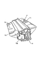
図1は、本発明の実施の形態に係るプロセスカートリッジを備えた画像形成装置(本実施の形態では、電子写真方式のレーザビームプリンタ)を示す概略構成図、図2は、本発明の実施の形態に係るプロセスカートリッジを示す概略断面図である。なお、図16に示した従来のプロセスカートリッジの構成部材と同一部材には同一符号を付して説明する。
【0014】
この画像形成装置(レーザビームプリンタ)Aは、電子写真画像形成プロセスによって像担持体としての感光ドラム7上に形成されたトナー像を記録媒体(用紙やOHPシートなど)2に転写して画像形成を行う。
【0015】
詳しくは、帯電手段としての帯電ローラ8によって回転している感光ドラム7に帯電を行ない、次いでこの感光ドラム7に露光装置1から入力される画像情報に応じたレーザ光を照射して感光ドラム7に画像情報に応じた静電潜像を形成する。露光装置1は、レーザダイオード1aから画像情報に応じて照射されるレーザ光を高速回転するポリゴンミラー1bで反射させ、レンズ1cと反射ミラー1dを介して感光ドラム7表面を走査露光する。
【0016】
そして、この静電潜像を現像装置9のトナー(現像剤)によって現像してトナー像を形成する。現像装置9は、図2に示すように、トナー容器11A内のトナーをトナー送り部材9bの回転によって現像ローラ9cへ送り出す。そして、固定磁石(不図示)を内蔵した現像ローラ9cを回転させるとともに、規制ブレード9dの弾性部材9d1によって摩擦帯電電荷を付与したトナー層を現像ローラ9cの表面に形成し、そのトナーを感光ドラム7の現像領域へ供給する。そして、そのトナーを感光ドラム7上の静電潜像へ転移させることによってトナー像を形成して可視像化する。なお、本実施の形態で使用した現像剤としてのトナーは、磁性粒子を樹脂中に分散した1成分磁性トナーである。
【0017】
そして、トナー像の形成と同期して、複数の給紙カセット3aにセットした所定サイズの用紙などの記録媒体2を、ピックアップローラ3b、搬送ローラ対3c,3d及びレジストローラ対3eなどによって、感光ドラム7と転写手段としての転写ローラ4間の転写ニップ部に搬送する。
【0018】
そして、感光ドラム7に形成されたトナー像を、転写バイアスが印加された転写ローラ4によって記録媒体2に転写する。その後、トナー像の転写を受けた記録媒体2を搬送ガイド3fで定着手段としての定着装置5へと搬送する。この定着装置5は、駆動ローラ5c及びヒータ5aを内蔵する定着ローラ5bを有しており、トナー像が転写された記録媒体2を駆動ローラ5cと定着ローラ5b間の定着ニップ部で挟持搬送して、通過する記録媒体2に熱及び圧力を印加して転写されたトナー像を定着する。
【0019】
そして、トナー像が定着された記録媒体2を、排出ローラ対3g,3h,3iで搬送して排出トレイ6へと排出する。この排出トレイ6は、画像形成装置本体14の上面に設けられている。なお、摺動可能なフラッパ3kを動作させ、排出ローラ対3mによってトナー像が定着された記録媒体2を画像形成装置本体14の側面から排出することもできる。
【0020】
そして、前記トナー像を記録媒体2に転写した後に、クリーニング器10のクリーニングブレード10aによって感光ドラム7上の残留トナーを除去して、次の画像形成動作に備える。
【0021】
本実施の形態の画像形成装置Aでは、上記の感光ドラム7、帯電ローラ8、現像装置9及びクリーニング器10は一体的にカートリッジ化されてプロセスカートリッジBとして構成されており、画像形成装置本体14に着脱自在に装着される。
【0022】
プロセスカートリッジBは、図2に示すように、トナーを収納したトナー容器11Aを有するトナー枠体11と、現像装置9を有する現像枠体12と、感光ドラム7、帯電ローラ8及びクリーニング器10、クリーニングブレード10aを有するクリーニング枠体13とを備えている。そして、このプロセスカートリッジBを、画像形成装置本体14に設けた装着手段としてのカートリッジ装着ガイド(不図示)に対して着脱可能に装着するものである。
【0023】
詳しくは、このカートリッジ装着ガイドは、図1に示すカバー35を開いて開状態とすることにより現れるカートリッジ装着スペースに設けられている。このカートリッジ装着ガイドには、図1に示す矢印X方向に傾斜する溝状のガイド部(図11、図12の16a,16c)が設けられており、プロセスカートリッジBの左右両端部に設けた位置決め用ガイド部材(図3、図5の13aR,13aL)をガイドする。
【0024】
このガイド部に沿ってプロセスカートリッジBを図1に示す矢印X方向に挿入し、カバー35を閉じることによってプロセスカートリッジBの画像形成装置本体14への装着が完了する。また、プロセスカートリッジBを画像形成装置本体14内から取り出すときには、上記した装着動作と逆の動作を行なう。
【0025】
また、プロセスカートリッジBには、画像情報に応じた光を露光装置1から感光ドラム7へ照射するための露光開口部1e、及び感光ドラム7を転写材2に対向するための転写開口部13nが設けてある。詳しくは、露光開口部1eはクリーニング枠体13に設けられており、転写開口部13nは現像枠体12とクリーニング枠体13との間に構成される。以下、本実施の形態におけるプロセスカートリッジBの詳細な構成について説明する。
【0026】
(プロセスカートリッジBのハウジングの構成)
本実施の形態に係るプロセスカートリッジBは、上述したようにトナー枠体11と現像枠体12及びクリーニング枠体13を結合してハウジングを構成している。
【0027】
図2に示すように、トナー枠体11には、トナー送り部材9bが回動可能に設けられている。現像枠体12には、現像ローラ9c及び規制ブレード9dが設けられており、現像ローラ9c近傍には、現像装置9内のトナーを循環させる撹拌部材9eが回動可能に設けられている。また、現像枠体12には、現像ローラ9cの長手方向と対向して、この現像ローラ9cと略平行にアンテナ棒9hが設けられている。更に、トナー枠体11には、プロセスカートリッジBを画像形成装置本体14から取り外したときに感光ドラム7を覆い、これを長時間光に晒されるあるいは異物との接触等から保護するドラムシャッタ部材18が設けられている。
【0028】
なお、図2において、9d1は規制ブレード9dの弾性部材、9d2は弾性部材9d1の保持部材、9iはスペーサコロ、9jは絶縁シート部材であり、これらについては後述する。
【0029】
トナー枠体11と現像枠体12は溶着(本実施の形態では超音波溶着)されることによって、一体的な現像ユニットD(図8参照)を構成している。また、クリーニング枠体13には、感光ドラム7、帯電ローラ8及びクリーニング器10の各部材を取り付けて、クリーニングユニットC(図9参照)が構成されている。
【0030】
そして、上記のクリーニングユニットCと現像ユニットDを丸いピン状の結合部材22により互いに回動可能に結合することによって、プロセスカートリッジBが構成されている。即ち、図8に示すように、現像枠体12の長手方向(現像ローラ9cの軸線方向)両側に形成したアーム部19の先端には、現像ローラ9cに平行に丸い形状の回動穴20が形成されている。
【0031】
一方、クリーニング枠体13の長手方向両側2箇所には、アーム部19を進入させるための凹部21が形成されている(図9参照)。そして、図8、図9のように、この凹部21に前記アーム部19を挿入し、結合部材22をクリーニング枠体13の取付け穴13eに圧入し、かつアーム部19端の回動穴20に嵌入して更に内側の穴13eに圧入して取り付けることにより、現像ユニットDとクリーニングユニットCは結合部材22を中心に回動可能に結合される。
【0032】
このとき、アーム部19の基体側に設けたダボ(不図示)に挿入して取り付けた圧縮コイルばね22aがクリーニング枠体13の凹部21の上壁に当り、この圧縮コイルばね22aによって現像枠体12を下方へ付勢することにより、現像ローラ9cが感光ドラム7に一定の付勢力によって当接される。
【0033】
(プロセスカートリッジB及び画像形成装置本体14のガイド手段の構成)
次に、プロセスカートリッジBを画像形成装置本体14に着脱する際のガイド手段について、図3〜図7を参照して説明する。図3は、プロセスカートリッジBの長手方向の一方から見た斜視図、図4は、プロセスカートリッジBの一方から見た側面図、図5は、プロセスカートリッジBの他方から見た側面図、図6は、プロセスカートリッジBの長手方向の他方から見た斜視図、図7は、プロセスカートリッジBの感光ドラム7側から見た斜視図である。
【0034】
クリーニング枠体13の両外側面には、図3〜図7に示すように、プロセスカートリッジBを画像形成装置本体14に着脱するときのガイドとなるガイド手段が設けられている。即ち、このガイド手段は、位置決め用ガイド部材としての円筒形ガイド13aR,13aLと、着脱時の姿勢保持手段たるガイド部材としての回り止めガイド13bRにより構成されている。
【0035】
図4に示すように、円筒形ガイド13aRは中空の円筒状部材であり、回り止めガイド13bRは円筒形ガイド13aRと一体成形であり、円筒形ガイド13aRの円周から一体でほぼ放射方向へ突出している。円筒形ガイド13aRには、取付けフランジ13aR1が一体に設けられている。このように、円筒形ガイド13aR、回り止めガイド13bR、取付けフランジ13aR1を有する右側ガイド部材13Rは、取付けフランジ13aR1の小ネジ用穴を挿通して各小ネジ13aR2をクリーニング枠体13にねじ込み固定されている。
【0036】
クリーニング枠体13に固定された右側ガイド部材13Rの回り止めガイド13bRは、現像枠体12に固定された現像ホルダ40の側方へ延出するように現像枠体12の側面側に配設されている。
【0037】
また、図10に示すように、フランジ29の内部側には、感光ドラム7に嵌入した平歯ギア7nを回転自在に支持する固定のドラム軸7aを備えており、クリーニング枠体13の穴13k1にドラム軸7aの拡径部7a2が嵌合している。そして、図5に示すように、クリーニング枠体13の側面に突出する位置決めピン13cに嵌合して回転止めされ、小ねじ13dでクリーニング枠体13に固定された平板状のフランジ29に外方(図5の紙面に直交して手前方向)へ向って円筒形ガイド13aLが突設されている。
【0038】
円筒形ガイド13aLとドラム軸7aは同軸上にあり、円筒形ガイド13aL、ドラム軸7a、フランジ29は、一体または一体的に金属材料、例えば鉄材で形成されている。
【0039】
なお、図9に示すように、平歯ギア7nは感光ドラム7の軸方向で、はす歯のドラムギア7bと反対側の端部に設けられている。この平歯ギア7nは、プロセスカートリッジBが画像形成装置本体14に装着された際に、画像形成装置本体14に設けられた転写ローラ4と同軸のギア(図示せず)と噛合して、転写ローラ4を回転させる駆動力をプロセスカートリッジBから伝達する。
【0040】
クリーニングユニットCの上面13iのプロセスカートリッジ装着方向(X方向)に対して直交する方向の左右の両端には、規制当接部13jがそれぞれ設けられている。なお、クリーニングユニットCの上面13iとは、プロセスカートリッジBを画像形成装置本体14に装着した際に、上方に位置する面である。
【0041】
規制当接部13jは、プロセスカートリッジBを画像形成装置本体14に装着した際に、プロセスカートリッジBの位置を規定するものである。即ち、プロセスカートリッジBを装置画像形成本体14に装着した際に、画像形成装置本体14に設けられた固設部材25(図11、図12参照)に規制当接部13jが当接することにより、プロセスカートリッジBの円筒形ガイド13aR,13aLを中心とする回動位置が規定される。
【0042】
次に、画像形成装置本体14側のガイド手段について述べる。画像形成装置本体14のカバー35を、支点35aを中心に図1において反時計回りに回動すると、画像形成装置本体14の上部が開放される(図11、図12参照)。このカバー35を開けた開口部から画像形成装置本体14の左右両側の内壁のプロセスカートリッジBの着脱方向から見て左側に図11、右側に図12に示すようにガイド部材16R,16Lがそれぞれ設けられている。
【0043】
ガイド部材16R,16Lには、プロセスカートリッジBの挿入方向の矢印Xから見て前下りになるように斜設したガイド部16a,16cと、このガイド部16a,16cにそれぞれつながりプロセスカートリッジBの円筒形ガイド13aR,13aLがちょうど嵌入する半円形の位置決め溝16b,16dをそれぞれ備えている。位置決め溝16b,16dは、周壁が円筒形をしている。この位置決め溝16b,16dの中心は、プロセスカートリッジBを画像形成装置本体14に装着時に、プロセスカートリッジBの円筒形ガイド13aR,13aLの中心と一致し、かつ感光ドラム7の中心線とも一致している。
【0044】
ガイド部16a,16cの幅は、プロセスカートリッジBの着脱方向から見て円筒形ガイド13aR,13aLが遊嵌する幅を有する。円筒形ガイド13aRの直径よりもそれぞれ狭い幅を持つ回り止めガイド13bRは当然緩く嵌まり込むが、円筒形ガイド13aR,13aL、回り止めガイド13bRはガイド部16aにより回動を制約され、プロセスカートリッジBは一定範囲の姿勢を保って装着される。
【0045】
そして、プロセスカートリッジBが画像形成装置本体14へ装着された状態においては、プロセスカートリッジBの円筒形ガイド13aR,13aLがそれぞれガイド部材13R,13Lの位置決め溝16b,16dに嵌合するとともに、プロセスカートリッジBのクリーニング枠体13先端左右の規制当接部13jが画像形成装置本体14の固設部材25に当接するようになっている。
【0046】
なお、プロセスカートリッジBは、円筒形ガイド13aR,13aLの中心を結ぶ中心線に対し、クリーニングユニットC側と現像ユニットD側ではこの中心線を水平に保つと、現像ユニットD側がクリーニングユニットC側よりも大きな一次モーメントを生ずるような重量配分になっている。
【0047】
プロセスカートリッジBを画像形成装置本体14に装着する際には、トナー枠体11の凹部17側及び下側のそれぞれのリブ11cを片手でつかみ、円筒形ガイド13aR,13aLを画像形成装置本体14のカートリッジ装着部のガイド部16a,16cへそれぞれ挿入し、続いて挿入方向から見てプロセスカートリッジBを前下りにして回り止めガイド13bRを画像形成装置本体14のガイド部16a,16cへ挿入する。
【0048】
すると、プロセスカートリッジBの円筒形ガイド13aR,13aL、回り止めガイド13bRは、画像形成装置本体14のガイド部16a,16cに沿って奥側へ進み、プロセスカートリッジBの円筒形ガイド13aR,13aLが画像形成装置本体14の位置決め溝16b,16dに達すると、この円筒形ガイド13aR,13aLは位置決め溝16b,16dの位置へプロセスカートリッジBの重力で着座する。これによって、位置決め溝16b,16dに対してプロセスカートリッジBの円筒形ガイド13aR,13aLは正確に位置が定まる。
【0049】
そして、円筒形ガイド13aR,13aLの中心を結ぶ中心線は感光ドラム7の中心線であるから、感光ドラム7は画像形成装置本体14に概略に位置が定まる。なお、最終的にはカップリングが結合した状態で、感光ドラム7は画像形成装置本体14に対する位置が決まる。
【0050】
この状態では、画像形成装置本体14の固設部材25とプロセスカートリッジBの規制当接部13j間には、僅かに隙間がある。ここで、プロセスカートリッジBを持っている手を離すと、プロセスカートリッジBはその円筒形ガイド13aR,13aLを中心にして現像ユニットD側が下り、クリーニングユニットC側が上昇し、プロセスカートリッジBの規制当接部13jは画像形成装置本体14の固設部材25に当接し、プロセスカートリッジBは画像形成装置本体14に対して正確に装着される。その後、カバー35を、図1において支点35aを中心に時計回りに回動して閉める。
【0051】
また、プロセスカートリッジBを画像形成装置本体14から取り外すのは、上記と逆で、画像形成装置本体14のカバー35を開いてプロセスカートリッジBの把手部をなす前述の上下のリブ11cに手を掛け持ち上げるようにすると、プロセスカートリッジBの円筒形ガイド13aR,13aLが画像形成装置本体14の位置決め溝16b,16dを中心に回動し、プロセスカートリッジBの規制当接部13jが画像形成装置本体14の固定部材25から離れる。
【0052】
そして、プロセスカートリッジBを更に引くと円筒形ガイド13aR,13aLが位置決め溝16b,16dから脱出して、画像形成装置本体14に固定したガイド部材16R,16Lのガイド部16a,16cへ移動し、そのまま、プロセスカートリッジBを引き上げると、プロセスカートリッジBの円筒形ガイド13aR,13aL、回り止めガイド13bR,13bLは画像形成装置本体14のガイド部16a,16c中を移動して上昇する。これによって、プロセスカートリッジBの姿勢が規制されて、プロセスカートリッジBは画像形成装置本体14の他の部分に当ることなく画像形成装置本体14外へ取り出される。
【0053】
(絶縁シート部材)
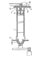
次に、本実施の形態の特徴である現像ローラ9cの両端部近傍に設けた絶縁シート部材9jについて、図13〜図15を参照して説明する。図13は、現像枠体を示す正面図、図14は、現像枠体を示す分解断面図、図15は、現像枠体を示す側面図である。
【0054】
プロセスカートリッジBの現像枠体12には現像ローラ9cが回転自在に支持されて設けられており、その長手方向両端部にはそれぞれスペーサコロ9iが装着されている。規制ブレード9dは、現像ローラ9cの長手方向に沿って当接しトナーを所定の層厚に規制する弾性部材9d1と、弾性部材9d1を保持し現像枠体12への固定部である保持部材9d2とで構成されている。保持部材9d2は導電性の部材によって形成されている。
【0055】
規制ブレード9dの弾性部材9d1は、現像ローラ9cを押圧して、現像ローラ9cが現像領域に担持搬送するトナー層の厚みを規制している。現像ローラ9cの長手方向両端部には現像剤掻き寄せブレード9lがそれぞれ配設されており、現像ローラ9c上のトナーが、飛散等でスペーサコロ9i方向に漏れ出すことを防いでいる。
【0056】
また、現像ローラ9cの長手方向両端近傍には、現像ローラ9cの外周面と所定隙間を持って磁石シール部材9mがそれぞれ配設されており、磁石シール部材9mの磁界作用によってトナーの現像枠体12外へのすり抜けや漏れ等を防止している。また、規制ブレード9dの保持部材9d2と磁石シール部材9mの間には、両者間の電気的な漏洩を防止するために、絶縁シート部材9jがそれぞれ挟み込まれている。
【0057】
絶縁シート部材9jは、磁石シール部材9mと現像ブレード9dの保持部材9d2に挟まれる位置に配設されており、現像剤掻き寄せブレード9lとともに現像枠体12に固着されている。そして、絶縁シート部材9jは、スペーサコロ9iに当接する位置まで延設されている。
【0058】
このように、絶縁シート部材9jはスペーサコロ9iの表面に当接しており、現像時に現像ローラ9cが回転すると、スペーサコロ9iは絶縁シート部材9jと接しながら回転する。よって、スペーサコロ9i上に飛散トナーが付着してもすぐに絶縁シート部材9jによって掻き取られ、トナーがスペーサコロ9i上に残留することはない。
【0059】
上記したように、本実施の形態におけるプロセスカートリッジBは、現像ローラ9cの長手方向両端部に設けたスペーサコロ9iに当接するようにして絶縁シート部材9jが配設されているので、スペーサコロ9i上に付着するトナーをこの絶縁シート部材9jにより掻きとることが可能となる。
【0060】
従って、プロセスカートリッジBを画像形成装置本体14に装着して画像形成を行う場合に、トナー飛散によってスペーサコロ9i上にトナーが付着することが防止されるので、現像ローラ9cと感光ドラム7との適切な隙間を安定して維持することができ、長期にわたって良好な現像を行うことができる。
【0061】
また、本実施の形態では、絶縁シート部材9jをスペーサコロ9iの表面に当接する位置まで延設する簡単な構成で、スペーサコロ9i上にトナーが付着することが防止することができるので、新たなトナー清掃部材を必要とせず、コストの低減が可能となる。
【0062】
また、上述した本実施の形態におけるプロセスカートリッジBを備えた画像形成装置は、単色画像を形成する画像形成装置の場合であったが、本発明に係るプロセスカートリッジは、現像手段を複数設け複数色の画像(例えば2色画像、3色画像あるいはフルカラー)を形成するプロセスカートリッジにも好適に適用することができる。
【0063】
また、現像手段による現像方法として、上述した本実施の形態では1成分現像法を用いたが、これ以外にも公知の2成分磁気ブラシ現像法、カスケード現像法、タッチダウン現像法、クラウド現像法等の種々の現像法を用いることができる。
【0064】
【発明の効果】
以上説明したように本発明の画像形成装置によれば、保持部材と磁気発生手段との間を電気的に絶縁する絶縁シート部材の少なくとも一部を、像担持体と現像剤担持体との間隔を一定に保持するスペーサコロに当接するようにして配設したことにより、スペーサコロ9i上に現像剤が付着しても絶縁シート部材によって除去することができるので、現像剤担持体と像担持体間の適切な隙間を安定して維持することができ、長期にわたって良好な現像を行うことができる。
【0065】
また、本発明のプロセスカートリッジによれば、保持部材と磁気発生手段との間を電気的に絶縁する絶縁シート部材の少なくとも一部を、像担持体と現像剤担持体との間隔を一定に保持するスペーサコロに当接するようにして配設したことにより、スペーサコロ9i上に現像剤が付着しても絶縁シート部材によって除去することができるので、現像剤担持体と像担持体間の適切な隙間を安定して維持することができ、長期にわたって良好な現像を行うことができる。
【図面の簡単な説明】
【図1】本発明の実施の形態に係るプロセスカートリッジを備えた画像形成装置を示す概略構成図。
【図2】本発明の実施の形態に係るプロセスカートリッジを示す側断面図。
【図3】本発明の実施の形態に係るプロセスカートリッジを示す斜視図。
【図4】本発明の実施の形態に係るプロセスカートリッジを示す側面図。
【図5】本発明の実施の形態に係るプロセスカートリッジを示す側面図。
【図6】本発明の実施の形態に係るプロセスカートリッジを示す斜視図。
【図7】本発明の実施の形態に係るプロセスカートリッジを示す斜視図。
【図8】本発明の実施の形態に係るプロセスカートリッジの現像ユニット、現像ローラユニット、トナー容器ユニットを示す分解斜視図。
【図9】本発明の実施の形態に係るプロセスカートリッジのクリーニングユニットを示す斜視図。
【図10】本発明の実施の形態における感光ドラムを示す断面図。
【図11】本発明の実施の形態における画像形成装置本体のプロセスカートリッジ装着部を示す斜視図。
【図12】本発明の実施の形態における画像形成装置本体のプロセスカートリッジ装着部を示す斜視図。
【図13】本発明の実施の形態における現像枠体を示す正面図。
【図14】本発明の実施の形態における現像枠体を示す分解断面図。
【図15】本発明の実施の形態における現像枠体を示す側面図。
【図16】従来例におけるプロセスカートリッジを示す側断面図。
【符号の説明】
1 露光装置
2 記録媒体
4 転写ローラ
5 定着装置
6 排紙トレイ
7 感光ドラム(像担持体)
8 帯電ローラ
9 現像装置
9c 現像ローラ(現像剤担持体)
9d 規制ブレード(現像剤層厚規制手段)
9d1 弾性部材
9d2 保持部材
9i スペーサコロ
9j 絶縁シート部材
9m 磁石シール部材(磁気発生手段)
10 クリーニング器
10a クリーニングブレード
11 トナー枠体
12 現像枠体
13 クリーニング枠体
14 画像形成装置本体
A 画像形成装置
B プロセスカートリッジ
C クリーニングユニット
D 現像ユニット[0001]
BACKGROUND OF THE INVENTION
The present invention has an image forming apparatus such as a copying machine, a printer, a facsimile, and the like that forms an image by using an electrophotographic system, and a photosensitive drum and at least a developing unit as an integral cartridge structure, and is detachable from the image forming apparatus. The present invention relates to a process cartridge that is freely mounted.
[0002]
[Prior art]
In an image forming apparatus using an electrophotographic system, it is necessary to change a photosensitive drum, supply and replace a developer, and adjust (clean) and replace other parts (such as a charger and a cleaning container) when the image forming apparatus is used for a long time. However, such maintenance work is practically difficult except for a service person having specialized knowledge.
[0003]
Therefore, in an image forming apparatus using an electrophotographic image forming process, the photosensitive drum and the process means acting on the photosensitive drum are integrally formed into a cartridge, and the cartridge can be attached to and detached from the image forming apparatus. The method is adopted. According to this process cartridge system, the maintenance of the apparatus can be performed by the user himself / herself without depending on the service person, so that the operability can be remarkably improved.
[0004]
FIG. 16 is a schematic sectional view showing a conventional process cartridge.
[0005]
The process cartridge B includes a developing
[0006]
In this case, in order to maintain an appropriate gap between the
[0007]
[Problems to be solved by the invention]
By the way, when the above-described conventional process cartridge B is mounted on the image forming apparatus to form an image, a small amount of toner scatters from the periphery of the developing
[0008]
When the scattered toner adheres to the peripheral surface of the
[0009]
In view of this, the present invention can prevent the scattered toner from adhering to the circumferential surfaces of the spacer rollers provided at both ends in the longitudinal direction of the developing roller, and maintain an appropriate gap between the developing roller and the photosensitive drum. An object is to provide an apparatus and a process cartridge.
[0010]
[Means for Solving the Problems]
In order to achieve the above object, the present invention according to claim 1 includes an image carrier and a developing unit that develops the electrostatic latent image formed on the image carrier and visualizes it as a developer image. In the image forming apparatus provided, the developing unit includes: A frame, In proximity to or in contact with the image carrier To the frame A developer that is rotatably supported and is magnetically supported on the surface by a magnetism generating member provided inside, and a developer is applied to the electrostatic latent image on the image carrier in the development region by applying a development bias. A developer carrying body that adheres to the developer carrying body, an elastic member that abuts along the longitudinal direction of the developer carrying body and regulates the layer thickness of the developer carried on the surface of the developer carrying body, and holds the elastic member And said Elasticity A developer layer thickness regulating means composed of a conductive holding member for bringing a member into contact with the developer carrier with a predetermined pressing force; and at least in the vicinity of both ends in the longitudinal direction of the developer carrier, A magnetism generating means disposed at a predetermined distance from the outer peripheral surface of the developer carrying member and magnetically sealing the leakage of the developer around the developer carrying member; The above Spacer rollers provided on both ends in the longitudinal direction of the surface of the developer carrier, and holding a constant distance between the image carrier and the developer carrier; A developer scraping blade that is provided at both ends in the longitudinal direction of the developer carrier and prevents the developer carried by the developer carrier from leaking in the spacer roller direction; and It is disposed so as to be sandwiched between the holding member of the developer layer thickness regulating means and the magnetism generating means at both longitudinal ends, and electrically insulates between the holding member and the magnetism generating means, At least some But The spacer roller When Contact And an insulating sheet member that removes the developer attached to the spacer rollers, and the insulating sheet member is fixed to the frame body together with the developer scraping blade. It is characterized by that.
[0011]
According to a second aspect of the present invention, the image bearing member and at least a developing unit that develops the electrostatic latent image formed on the image bearing member and visualizes it as a developer image are integrated. In the process cartridge having a simple cartridge configuration and detachably attached to the image forming apparatus, the developing unit includes: A frame, In proximity to or in contact with the image carrier To the frame A developer that is rotatably supported and is magnetically supported on the surface by a magnetism generating member provided inside, and a developer is applied to the electrostatic latent image on the image carrier in the development region by applying a development bias. A developer carrying body that adheres to the developer carrying body, an elastic member that abuts along the longitudinal direction of the developer carrying body and regulates the layer thickness of the developer carried on the surface of the developer carrying body, and holds the elastic member And said Elasticity A developer layer thickness regulating means composed of a conductive holding member for bringing a member into contact with the developer carrier with a predetermined pressing force; and at least in the vicinity of both ends in the longitudinal direction of the developer carrier, A magnetism generating means disposed at a predetermined distance from the outer peripheral surface of the developer carrying member and magnetically sealing the leakage of the developer around the developer carrying member; The above Spacer rollers provided on both ends in the longitudinal direction of the surface of the developer carrier, and holding a constant distance between the image carrier and the developer carrier; A developer scraping blade that is provided at both ends in the longitudinal direction of the developer carrier and prevents the developer carried by the developer carrier from leaking in the spacer roller direction; and It is disposed so as to be sandwiched between the holding member of the developer layer thickness regulating means and the magnetism generating means at both longitudinal ends, and electrically insulates between the holding member and the magnetism generating means, At least some But The spacer roller When Contact And an insulating sheet member that removes the developer attached to the spacer rollers, and the insulating sheet member is fixed to the frame body together with the developer scraping blade. It is characterized by that.
[0012]
DETAILED DESCRIPTION OF THE INVENTION
Hereinafter, the present invention will be described based on the illustrated embodiments.
[0013]
FIG. 1 is a schematic configuration diagram illustrating an image forming apparatus (in this embodiment, an electrophotographic laser beam printer) including a process cartridge according to an embodiment of the present invention, and FIG. 2 is a diagram illustrating an embodiment of the present invention. It is a schematic sectional drawing which shows the process cartridge which concerns on a form. The same members as those of the conventional process cartridge shown in FIG.
[0014]
This image forming apparatus (laser beam printer) A forms an image by transferring a toner image formed on a
[0015]
Specifically, the
[0016]
The electrostatic latent image is developed with toner (developer) in the developing
[0017]
In synchronism with the formation of the toner image, the
[0018]
Then, the toner image formed on the
[0019]
Then, the
[0020]
After the toner image is transferred to the
[0021]
In the image forming apparatus A of the present embodiment, the
[0022]
As shown in FIG. 2, the process cartridge B includes a
[0023]
Specifically, the cartridge mounting guide is provided in a cartridge mounting space that appears when the
[0024]
The process cartridge B is inserted along the guide portion in the direction of the arrow X shown in FIG. 1 and the
[0025]
Further, the process cartridge B has an
[0026]
(Configuration of housing of process cartridge B)
In the process cartridge B according to the present embodiment, as described above, the
[0027]
As shown in FIG. 2, the
[0028]
In FIG. 2, 9d1 is an elastic member of the
[0029]
The
[0030]
Then, the process cartridge B is configured by coupling the cleaning unit C and the developing unit D to each other by a round pin-shaped
[0031]
On the other hand, at two locations on both sides of the
[0032]
At this time, the
[0033]
(Configuration of guide means of process cartridge B and image forming apparatus main body 14)
Next, guide means for attaching / detaching the process cartridge B to / from the image forming apparatus
[0034]
As shown in FIGS. 3 to 7, guide means that serve as a guide when the process cartridge B is attached to and detached from the image forming apparatus
[0035]
As shown in FIG. 4, the cylindrical guide 13aR is a hollow cylindrical member, and the anti-rotation guide 13bR is integrally formed with the cylindrical guide 13aR, and integrally protrudes from the circumference of the cylindrical guide 13aR substantially in the radial direction. ing. A mounting flange 13aR1 is provided integrally with the cylindrical guide 13aR. As described above, the
[0036]
The detent guide 13bR of the
[0037]
As shown in FIG. 10, a fixed
[0038]
The cylindrical guide 13aL and the
[0039]
As shown in FIG. 9, the
[0040]
On both the left and right ends of the
[0041]
The
[0042]
Next, guide means on the image forming apparatus
[0043]
The
[0044]
The widths of the
[0045]
When the process cartridge B is mounted on the image forming apparatus
[0046]
In the process cartridge B, if the central line connecting the centers of the cylindrical guides 13aR and 13aL is kept horizontal on the cleaning unit C side and the developing unit D side, the developing unit D side is more than the cleaning unit C side. The weight distribution is such that a large first moment is generated.
[0047]
When the process cartridge B is mounted on the image forming apparatus
[0048]
Then, the cylindrical guides 13aR and 13aL and the rotation prevention guide 13bR of the process cartridge B proceed to the back side along the
[0049]
Since the center line connecting the centers of the cylindrical guides 13aR and 13aL is the center line of the
[0050]
In this state, there is a slight gap between the fixed
[0051]
The process cartridge B is removed from the image forming apparatus
[0052]
When the process cartridge B is further pulled, the cylindrical guides 13aR and 13aL escape from the
[0053]
(Absolute Edge Material)
Next, an insulating film provided near both ends of the developing
[0054]
A developing
[0055]
The elastic member 9d1 of the
[0056]
Further,
[0057]
Absolute Edge The
[0058]
Like this Edge The
[0059]
As described above, the process cartridge B in the present embodiment is completely disconnected so as to contact the
[0060]
Accordingly, when the process cartridge B is mounted on the image forming apparatus
[0061]
In this embodiment, the absolute Edge Since the
[0062]
The image forming apparatus provided with the process cartridge B in the present embodiment described above is a case of an image forming apparatus that forms a single color image. However, the process cartridge according to the present invention includes a plurality of developing units and a plurality of colors The present invention can also be suitably applied to a process cartridge that forms an image (for example, a two-color image, a three-color image, or a full color).
[0063]
Further, as the developing method by the developing means, the one-component developing method is used in the above-described embodiment, but other known two-component magnetic brush developing methods, cascade developing methods, touch-down developing methods, cloud developing methods are also used. Various development methods such as these can be used.
[0064]
【The invention's effect】
As described above, according to the image forming apparatus of the present invention, the insulating member that electrically insulates between the holding member and the magnetism generating means. Edge By disposing at least a part of the support member in contact with a spacer roller that keeps the distance between the image carrier and the developer carrier constant, even if the developer adheres to the
[0065]
In addition, according to the process cartridge of the present invention, the insulation between the holding member and the magnetism generating means is electrically insulated. Edge By disposing at least a part of the support member in contact with a spacer roller that keeps the distance between the image carrier and the developer carrier constant, even if the developer adheres to the
[Brief description of the drawings]
FIG. 1 is a schematic configuration diagram illustrating an image forming apparatus including a process cartridge according to an embodiment of the present invention.
FIG. 2 is a side sectional view showing a process cartridge according to an embodiment of the present invention.
FIG. 3 is a perspective view showing a process cartridge according to an embodiment of the present invention.
FIG. 4 is a side view showing a process cartridge according to the embodiment of the present invention.
FIG. 5 is a side view showing a process cartridge according to the embodiment of the present invention.
FIG. 6 is a perspective view showing a process cartridge according to the embodiment of the invention.
FIG. 7 is a perspective view showing a process cartridge according to the embodiment of the invention.
FIG. 8 is an exploded perspective view showing a developing unit, a developing roller unit, and a toner container unit of the process cartridge according to the embodiment of the invention.
FIG. 9 is a perspective view showing a cleaning unit for a process cartridge according to an embodiment of the present invention.
FIG. 10 is a cross-sectional view showing a photosensitive drum in an embodiment of the present invention.
FIG. 11 is a perspective view showing a process cartridge mounting portion of the image forming apparatus main body according to the embodiment of the present invention.
FIG. 12 is a perspective view showing a process cartridge mounting portion of the main body of the image forming apparatus according to the embodiment of the present invention.
FIG. 13 is a front view showing a developing frame in the embodiment of the present invention.
FIG. 14 is an exploded cross-sectional view showing a developing frame in the embodiment of the present invention.
FIG. 15 is a side view showing a developing device frame according to the embodiment of the present invention.
FIG. 16 is a side sectional view showing a process cartridge in a conventional example.
[Explanation of symbols]
1 Exposure equipment
2 recording media
4 Transfer roller
5 Fixing device
6 Output tray
7 Photosensitive drum (image carrier)
8 Charging roller
9 Development device
9c Development roller (developer carrier)
9d regulating blade (developer layer thickness regulating means)
9d1 elastic member
9d2 holding member
9i Spacer roller
9j Edge Material
9m magnet seal member (magnetic generation means)
10 Cleaning device
10a Cleaning blade
11 Toner frame
12 Development frame
13 Cleaning frame
14 Image forming apparatus body
A Image forming apparatus
B Process cartridge
C Cleaning unit
D Development unit
Claims (2)
前記現像手段は、枠体と、
前記像担持体と近接又は当接するようにして、前記枠体に回転自在に支持され、磁性を有する現像剤を内部に設けた磁気発生部材によって表面に磁気的に担持して現像バイアスの印加により現像領域にて前記像担持体上の静電潜像に現像剤を付着させる現像剤担持体と、
前記現像剤担持体の長手方向に沿って当接し、前記現像剤担持体表面に担持される現像剤の層厚を規制する弾性部材と、前記弾性部材を保持して前記弾性部材を前記現像剤担持体に所定の押圧力で当接させる導電性の保持部材とで構成される現像剤層厚規制手段と、
前記現像剤担持体の少なくともその長手方向両端部近傍で、前記現像剤担持体の外周面と所定間隔を持って配設され、前記現像剤担持体の周囲に現像剤が漏れるのを磁気的にシールする磁気発生手段と、
前記現像剤担持体表面の長手方向両端側に設けられ、前記像担持体と前記現像剤担持体との間隔を一定に保持するスペーサコロと、
前記現像剤担持体の長手方向両端部にそれぞれ設けられ、前記現像剤担持体が担持する現像剤が、前記スペーサコロ方向に漏れ出すことを抑える現像剤掻き寄せブレードと、
前記現像剤担持体の長手方向両端部で前記現像剤層厚規制手段の前記保持部材と前記磁気発生手段とに挟まれるように配設され、前記保持部材と前記磁気発生手段との間を電気的に絶縁し、少なくとも一部が、前記スペーサコロと当接して、前記スペーサコロに付着した現像剤を除去する絶縁シート部材と、を有し、
前記絶縁シート部材は、前記現像剤掻き寄せブレードと共に前記枠体に固定される、
ことを特徴とする画像形成装置。In an image forming apparatus comprising: an image carrier; and a developing unit that develops an electrostatic latent image formed on the image carrier and visualizes it as a developer image.
The developing means includes a frame,
By applying a developing bias by magnetically supporting the surface of the image carrier by a magnetism generating member that is rotatably supported by the frame so as to be close to or in contact with the image carrier and provided with magnetism. A developer carrier for attaching a developer to the electrostatic latent image on the image carrier in a development region;
An elastic member that contacts along the longitudinal direction of the developer carrying member and regulates a layer thickness of the developer carried on the surface of the developer carrying member; and holds the elastic member to hold the elastic member to the developer A developer layer thickness regulating means composed of a conductive holding member that is brought into contact with the carrier with a predetermined pressing force;
At least in the vicinity of both ends in the longitudinal direction of the developer carrying member, the developer carrying member is disposed with a predetermined distance from the outer peripheral surface of the developer carrying member, and magnetically leaks the developer around the developer carrying member. Magnetic generating means for sealing ;
Provided in the longitudinal direction both ends of the developer carrying member surface, and spacer rollers for holding an interval between the image bearing member and said developer carrying member at a constant,
A developer scraping blade that is provided at each of both ends in the longitudinal direction of the developer carrier and suppresses leakage of the developer carried by the developer carrier in the spacer roller direction;
The developer carrying member is disposed so as to be sandwiched between the holding member of the developer layer thickness regulating means and the magnetism generating means at both ends in the longitudinal direction of the developer carrying member. insulates at least partly, the spacer roller and to contact, has an insulating sheet member to remove the developer adhered to the spacer rollers,
The insulating sheet member is fixed to the frame body together with the developer scraping blade.
An image forming apparatus.
前記現像手段は、枠体と、
前記像担持体と近接又は当接するようにして、前記枠体に回転自在に支持され、磁性を有する現像剤を内部に設けた磁気発生部材によって表面に磁気的に担持して現像バイアスの印加により現像領域にて前記像担持体上の静電潜像に現像剤を付着させる現像剤担持体と、
前記現像剤担持体の長手方向に沿って当接し、前記現像剤担持体表面に担持される現像剤の層厚を規制する弾性部材と、前記弾性部材を保持して前記弾性部材を前記現像剤担持体に所定の押圧力で当接させる導電性の保持部材とで構成される現像剤層厚規制手段と、
前記現像剤担持体の少なくともその長手方向両端部近傍で、前記現像剤担持体の外周面と所定間隔を持って配設され、前記現像剤担持体の周囲に現像剤が漏れるのを磁気的にシールする磁気発生手段と、
前記現像剤担持体表面の長手方向両端側に設けられ、前記像担持体と前記現像剤担持体との間隔を一定に保持するスペーサコロと、
前記現像剤担持体の長手方向両端部にそれぞれ設けられ、前記現像剤担持体が担持する現像剤が、前記スペーサコロ方向に漏れ出すことを抑える現像剤掻き寄せブレードと、
前記現像剤担持体の長手方向両端部で前記現像剤層厚規制手段の前記保持部材と前記磁気発生手段とに挟まれるように配設され、前記保持部材と前記磁気発生手段との間を電気的に絶縁し、少なくとも一部が、前記スペーサコロと当接して、前記スペーサコロに付着した現像剤を除去する絶縁シート部材と、を有し、
前記絶縁シート部材は、前記現像剤掻き寄せブレードと共に前記枠体に固定される、
ことを特徴とするプロセスカートリッジ。At least an image carrier and a developing unit that develops the electrostatic latent image formed on the image carrier and visualizes it as a developer image has an integral cartridge configuration and is detachable from the image forming apparatus In the process cartridge attached to
The developing means includes a frame,
By applying a developing bias by magnetically supporting the surface of the image carrier by a magnetism generating member that is rotatably supported by the frame so as to be close to or in contact with the image carrier and provided with magnetism. A developer carrier for attaching a developer to the electrostatic latent image on the image carrier in a development region;
An elastic member that contacts along the longitudinal direction of the developer carrying member and regulates a layer thickness of the developer carried on the surface of the developer carrying member; and holds the elastic member to hold the elastic member to the developer A developer layer thickness regulating means composed of a conductive holding member that is brought into contact with the carrier with a predetermined pressing force;
At least in the vicinity of both ends in the longitudinal direction of the developer carrying member, the developer carrying member is disposed with a predetermined distance from the outer peripheral surface of the developer carrying member, and magnetically leaks the developer around the developer carrying member. Magnetic generating means for sealing ;
Provided in the longitudinal direction both ends of the developer carrying member surface, and spacer rollers for holding an interval between the image bearing member and said developer carrying member at a constant,
A developer scraping blade that is provided at each of both ends in the longitudinal direction of the developer carrier and suppresses leakage of the developer carried by the developer carrier in the spacer roller direction;
The developer carrying member is disposed so as to be sandwiched between the holding member of the developer layer thickness regulating means and the magnetism generating means at both ends in the longitudinal direction of the developer carrying member. insulates at least partly, the spacer roller and to contact, has an insulating sheet member to remove the developer adhered to the spacer rollers,
The insulating sheet member is fixed to the frame body together with the developer scraping blade.
A process cartridge characterized by that.
Priority Applications (2)
| Application Number | Priority Date | Filing Date | Title |
|---|---|---|---|
| JP2001034155A JP4745511B2 (en) | 2001-02-09 | 2001-02-09 | Image forming apparatus and process cartridge |
| US10/066,635 US6606469B2 (en) | 2001-02-09 | 2002-02-06 | Developing apparatus mounted on image forming apparatus |
Applications Claiming Priority (1)
| Application Number | Priority Date | Filing Date | Title |
|---|---|---|---|
| JP2001034155A JP4745511B2 (en) | 2001-02-09 | 2001-02-09 | Image forming apparatus and process cartridge |
Publications (3)
| Publication Number | Publication Date |
|---|---|
| JP2002236419A JP2002236419A (en) | 2002-08-23 |
| JP2002236419A5 JP2002236419A5 (en) | 2008-03-21 |
| JP4745511B2 true JP4745511B2 (en) | 2011-08-10 |
Family
ID=18897814
Family Applications (1)
| Application Number | Title | Priority Date | Filing Date |
|---|---|---|---|
| JP2001034155A Expired - Fee Related JP4745511B2 (en) | 2001-02-09 | 2001-02-09 | Image forming apparatus and process cartridge |
Country Status (2)
| Country | Link |
|---|---|
| US (1) | US6606469B2 (en) |
| JP (1) | JP4745511B2 (en) |
Families Citing this family (15)
| Publication number | Priority date | Publication date | Assignee | Title |
|---|---|---|---|---|
| US20030214747A1 (en) * | 2002-05-14 | 2003-11-20 | Debasis Baral | Servo writing method for hard disk drives |
| JP2004144803A (en) | 2002-10-22 | 2004-05-20 | Canon Inc | Developing apparatus and process cartridge |
| JP4261872B2 (en) * | 2002-10-29 | 2009-04-30 | キヤノン株式会社 | Development device |
| JP4366067B2 (en) | 2002-11-07 | 2009-11-18 | キヤノン株式会社 | Developing device, process cartridge, and image forming apparatus |
| US7324775B2 (en) * | 2004-03-08 | 2008-01-29 | Seiko Epson Corporation | Image forming apparatus having developing device with sealing members and method of manufacture |
| JP4448122B2 (en) * | 2006-11-15 | 2010-04-07 | キヤノン株式会社 | Developing device and process cartridge |
| JP4721471B2 (en) | 2009-03-23 | 2011-07-13 | キヤノン株式会社 | Electrophotographic image forming apparatus |
| JP4605821B2 (en) * | 2009-03-23 | 2011-01-05 | キヤノン株式会社 | Electrophotographic image forming apparatus |
| JP4569977B1 (en) | 2009-03-23 | 2010-10-27 | キヤノン株式会社 | Electrophotographic image forming apparatus |
| JP4569978B1 (en) * | 2009-03-23 | 2010-10-27 | キヤノン株式会社 | Color electrophotographic image forming apparatus |
| JP4562208B1 (en) * | 2009-03-23 | 2010-10-13 | キヤノン株式会社 | Color electrophotographic image forming apparatus |
| JP4846033B2 (en) * | 2009-03-26 | 2011-12-28 | キヤノン株式会社 | Electrophotographic image forming apparatus |
| JP6253300B2 (en) | 2013-08-09 | 2017-12-27 | キヤノン株式会社 | Developing device and process cartridge |
| JP6261280B2 (en) | 2013-08-09 | 2018-01-17 | キヤノン株式会社 | Development device |
| JP6131800B2 (en) * | 2013-09-20 | 2017-05-24 | ブラザー工業株式会社 | cartridge |
Family Cites Families (10)
| Publication number | Priority date | Publication date | Assignee | Title |
|---|---|---|---|---|
| JPS5920246U (en) * | 1982-07-28 | 1984-02-07 | コニカ株式会社 | recording device |
| JP2646393B2 (en) * | 1989-05-31 | 1997-08-27 | キヤノン株式会社 | Developing device |
| EP0585882B1 (en) * | 1992-08-31 | 1997-10-29 | Kabushiki Kaisha Toshiba | Developing device and cleaning device used in electrophotographic apparatus |
| JP3267470B2 (en) * | 1995-06-30 | 2002-03-18 | キヤノン株式会社 | Process cartridge |
| JP3372747B2 (en) * | 1996-02-09 | 2003-02-04 | キヤノン株式会社 | Developing device |
| JP3352329B2 (en) * | 1996-07-26 | 2002-12-03 | キヤノン株式会社 | Developing device and process cartridge having the same |
| JP3837815B2 (en) * | 1997-02-27 | 2006-10-25 | ブラザー工業株式会社 | Developing device and image forming apparatus |
| JP3542473B2 (en) * | 1997-10-30 | 2004-07-14 | キヤノン株式会社 | Developing device, process cartridge and image forming device |
| JP4235269B2 (en) * | 1997-10-30 | 2009-03-11 | キヤノン株式会社 | Developing device, process cartridge, and image forming apparatus |
| JP3403094B2 (en) * | 1998-10-28 | 2003-05-06 | キヤノン株式会社 | Developing device, process cartridge, and electrophotographic image forming device |
-
2001
- 2001-02-09 JP JP2001034155A patent/JP4745511B2/en not_active Expired - Fee Related
-
2002
- 2002-02-06 US US10/066,635 patent/US6606469B2/en not_active Expired - Fee Related
Also Published As
| Publication number | Publication date |
|---|---|
| JP2002236419A (en) | 2002-08-23 |
| US6606469B2 (en) | 2003-08-12 |
| US20020110383A1 (en) | 2002-08-15 |
Similar Documents
| Publication | Publication Date | Title |
|---|---|---|
| JP3472108B2 (en) | Process cartridge and electrophotographic image forming apparatus | |
| JP4125007B2 (en) | Process cartridge and electrophotographic image forming apparatus | |
| JP4745511B2 (en) | Image forming apparatus and process cartridge | |
| JP3684195B2 (en) | Process cartridge and electrophotographic image forming apparatus | |
| JP2004125870A (en) | Reproduction method for process cartridge | |
| JP3554164B2 (en) | Process cartridge, electrophotographic image forming apparatus and seal member | |
| EP1209538B1 (en) | Electric contact member and developing device, process cartridge, and electrophotographic image-forming apparatus using the electric contact member | |
| JP2003208074A (en) | Process cartridge and electrophotographic image forming device | |
| JP4630615B2 (en) | Process cartridge and process cartridge assembly method | |
| KR100338203B1 (en) | Developing apparatus | |
| JP2000315006A (en) | Developing device, process cartridge, electrophotographic image forming device, and power feed component | |
| JP2002196647A (en) | Process cartridge and image forming device | |
| JP2001255741A (en) | Partition member, sealing parts, developing device and process cartridge | |
| JP3542564B2 (en) | Process cartridge remanufacturing method | |
| JP2001194977A (en) | Process cartridge and image forming device | |
| JPH05297649A (en) | Process cartridge and image forming device | |
| JP3848124B2 (en) | Process cartridge and electrophotographic image forming apparatus | |
| JP3542509B2 (en) | Magnetic seal member, developing device, process cartridge, and electrophotographic image forming device | |
| JPH09222786A (en) | Developing device, process cartridge, and image forming device | |
| JPH11184353A (en) | Process cartridge and electrophotographic image forming device | |
| JPH0792885A (en) | Process cartridge and image forming device | |
| JP2002108098A (en) | Process cartridge and electrophotographic image forming device | |
| JPH07104635A (en) | Process cartridge and image forming device | |
| JP2004101671A (en) | Developing apparatus, electrophotographic image forming apparatus, and bushing member | |
| JPH0720665A (en) | Process cartridge and image forming device |
Legal Events
| Date | Code | Title | Description |
|---|---|---|---|
| A521 | Request for written amendment filed |
Free format text: JAPANESE INTERMEDIATE CODE: A523 Effective date: 20080205 |
|
| A621 | Written request for application examination |
Free format text: JAPANESE INTERMEDIATE CODE: A621 Effective date: 20080205 |
|
| A977 | Report on retrieval |
Free format text: JAPANESE INTERMEDIATE CODE: A971007 Effective date: 20101013 |
|
| A131 | Notification of reasons for refusal |
Free format text: JAPANESE INTERMEDIATE CODE: A131 Effective date: 20101019 |
|
| A521 | Request for written amendment filed |
Free format text: JAPANESE INTERMEDIATE CODE: A523 Effective date: 20101216 |
|
| TRDD | Decision of grant or rejection written | ||
| A01 | Written decision to grant a patent or to grant a registration (utility model) |
Free format text: JAPANESE INTERMEDIATE CODE: A01 Effective date: 20110510 |
|
| A01 | Written decision to grant a patent or to grant a registration (utility model) |
Free format text: JAPANESE INTERMEDIATE CODE: A01 |
|
| A61 | First payment of annual fees (during grant procedure) |
Free format text: JAPANESE INTERMEDIATE CODE: A61 Effective date: 20110512 |
|
| FPAY | Renewal fee payment (event date is renewal date of database) |
Free format text: PAYMENT UNTIL: 20140520 Year of fee payment: 3 |
|
| R150 | Certificate of patent or registration of utility model |
Free format text: JAPANESE INTERMEDIATE CODE: R150 |
|
| LAPS | Cancellation because of no payment of annual fees |