EP0789172A2 - Hydraulische Servoeinrichtung für Automatikgetriebe - Google Patents
Hydraulische Servoeinrichtung für Automatikgetriebe Download PDFInfo
- Publication number
- EP0789172A2 EP0789172A2 EP96119369A EP96119369A EP0789172A2 EP 0789172 A2 EP0789172 A2 EP 0789172A2 EP 96119369 A EP96119369 A EP 96119369A EP 96119369 A EP96119369 A EP 96119369A EP 0789172 A2 EP0789172 A2 EP 0789172A2
- Authority
- EP
- European Patent Office
- Prior art keywords
- hydraulic servo
- rod
- gear stage
- automatic transmission
- band
- Prior art date
- Legal status (The legal status is an assumption and is not a legal conclusion. Google has not performed a legal analysis and makes no representation as to the accuracy of the status listed.)
- Withdrawn
Links
- 230000005540 biological transmission Effects 0.000 title claims abstract description 33
- 230000000903 blocking effect Effects 0.000 claims description 4
- 238000010276 construction Methods 0.000 description 20
- 230000004044 response Effects 0.000 description 14
- XDDAORKBJWWYJS-UHFFFAOYSA-N glyphosate Chemical compound OC(=O)CNCP(O)(O)=O XDDAORKBJWWYJS-UHFFFAOYSA-N 0.000 description 6
- 230000008859 change Effects 0.000 description 4
- 238000010586 diagram Methods 0.000 description 4
- 230000009467 reduction Effects 0.000 description 4
- 230000000694 effects Effects 0.000 description 3
- 230000035939 shock Effects 0.000 description 3
- 238000006243 chemical reaction Methods 0.000 description 2
- 238000006073 displacement reaction Methods 0.000 description 2
- 230000007246 mechanism Effects 0.000 description 2
- 238000002360 preparation method Methods 0.000 description 2
- 239000000969 carrier Substances 0.000 description 1
- 229910052729 chemical element Inorganic materials 0.000 description 1
- 230000006835 compression Effects 0.000 description 1
- 238000007906 compression Methods 0.000 description 1
- 238000001514 detection method Methods 0.000 description 1
- 230000002542 deteriorative effect Effects 0.000 description 1
- 230000006872 improvement Effects 0.000 description 1
- 230000004048 modification Effects 0.000 description 1
- 238000012986 modification Methods 0.000 description 1
- 235000002020 sage Nutrition 0.000 description 1
Images


Classifications
-
- F—MECHANICAL ENGINEERING; LIGHTING; HEATING; WEAPONS; BLASTING
- F16—ENGINEERING ELEMENTS AND UNITS; GENERAL MEASURES FOR PRODUCING AND MAINTAINING EFFECTIVE FUNCTIONING OF MACHINES OR INSTALLATIONS; THERMAL INSULATION IN GENERAL
- F16H—GEARING
- F16H63/00—Control outputs from the control unit to change-speed- or reversing-gearings for conveying rotary motion or to other devices than the final output mechanism
- F16H63/02—Final output mechanisms therefor; Actuating means for the final output mechanisms
- F16H63/30—Constructional features of the final output mechanisms
- F16H63/3003—Band brake actuating mechanisms
Definitions
- the present invention relates to a band brake for an automatic transmission and, more particularly, to a hydraulic servo-mechanism for fastening the brake band on a drum so as to apply it.
- the band brake exemplifies one mode of the engaging element for fixing a specific speed change element on a transmission case so as to change a gear stage to be established.
- the hydraulic servo-mechanism for fastening the brake band of the band brake on the drum applies/releases the brake by moving its rod between two positions, i.e., an apply position and a release position.
- This hydraulic servo-mechanism is disclosed in U.S. Patent 4,787,494.
- the aforementioned band brake as arranged in the case of the automatic transmission, is always held in an oil-lubricated state together with other elements in the case, so that at the brake-releasing time the oil existing in the gap between the brake band and the drum is dragged by the rotation of the drum to cause a dragging loss.
- the clearance between the band and the drum is enlarged at the brake releasing time to such a level as to cause no dragging resistance. If this is done, the rod of the hydraulic servo for applying the brake has to be displaced by a large stroke at the brake applying time to deteriorate the response for the brake application.
- a first object of the present invention to provide a hydraulic servo-mechanism for an automatic transmission, which is enabled to reduce the dragging loss at a brake releasing time without deteriorating the response at the brake applying time, by making it possible to set the operational positions of a hydraulic servo selectively.
- a second object of the present invention is to optimize the setting of the operational positions of the hydraulic servo for the application thereby to prevent the drop in the application response at a shifting time, by determining the selective setting of the operational positions of the hydraulic servo in the shifting order of the gear stages of the transmission.
- a third object of the present invention to make the reduction in the dragging loss the more effective for the improvement in the mileage by setting the operational position of the hydraulic servo, as making the reduction in the dragging loss at the brake releasing time, to the higher gear stage.
- a fourth object of the present invention is to shift the rod of the hydraulic servo reliably to each of the set positions to be selected, merely by supplying the oil pressures oppositely to the hydraulic servo.
- a fifth object of the present invention is to reduce the application shocks of the band brake while achieving the above-specified individual objects.
- a sixth object of the present invention is to effect the shift of the rod of the hydraulic servo to the retracted position by a simple circuit construction in accordance with the gear stages of the transmission.
- a seventh object of the present invention to prevent the drop in the application response at the skip shift, too, by making it possible to set the operational positions of the hydraulic servo selectively in accordance with the skip shift.
- the brake band has an elasticity in its expanding direction, and a satisfactory clearance may not always be established all over the circumference of the drum by the band due to a deformation or the like of the band even if the brake band is released by setting the operational positions of the hydraulic servo. It is, therefore, an eighth object of the present invention to make the reduction in the dragging loss more effective by holding the clearance satisfactory at the brake releasing time.
- a ninth object of the present invention is to prevent the interference between the band and the drum, as might otherwise be caused by the vibrations or the like at the time of releasing the band brake.
- a hydraulic servo-mechanism for an automatic transmission which mechanism comprises such a band brake as an engaging element as applies a band to a drum by a hydraulic servo, wherein the hydraulic servo includes a rod to be selectively set to an apply position for applying the band brake, a standby position in which the rod is retracted by a predetermined extent in a release direction from the apply position, and a retracted position in which the rod is further retracted in the release direction from the standby position to release the band brake.
- the automatic transmission achieves at least a first gear stage by applying the band brake, a second gear stage close to the first gear stage, and a third gear stage interposing the second gear stage between itself and the first gear stage, and the rod of the hydraulic servo is set to the apply position for establishing the first gear stage, the standby position at the second gear stage, and the retracted position at the third gear stage.
- the third gear stage is higher than the first and second gear stages.
- the hydraulic servo has an apply oil chamber to be supplied with the oil pressure for pushing the rod in an apply direction, and a return oil chamber to be supplied with an oil pressure for pushing in the release direction, and the rod is set to the apply position by supplying the oil pressure to the apply oil chamber, the standby position by releasing the oil pressure from the return oil chamber and the apply oil chamber, and the retracted position by supplying the oil pressure to the return oil chamber.
- the hydraulic servo includes: a first piston fixed immovably on the rod and fitted movably in the cylinder of the hydraulic servo for defining the return oil chamber with itself and the cylinder; a second piston supported by the rod slidably in the axial direction only by a predetermined extent and fitted movably in the cylinder for defining the apply oil chamber between itself and the cylinder; a separate spring for separating the first piston and the second piston axially from each other; and a return spring for urging the second piston in the release direction.
- the oil pressure to be supplied to the return oil chamber is one for another hydraulic servo acting as an engaging element to be applied for establishing the third gear stage.
- the third gear stage is higher than the first and second gear stages, and the return oil passage and the another hydraulic servo acting as the engaging element to be applied for establishing the third gear stage are connected through an oil passage in which is arranged a valve for blocking the oil pas sage when the throttle opening of an engine connected to the automatic transmission exceeds a predetermined value.
- the case of the automatic transmission has a support face for supporting the outer circumference of the band, which is retrained at its one end side by an anchor pin and expanded by its own elasticity, in the retracted position of the rod over a predetermined range thereby to restrict the expansion of the band.
- the support face supports the band in the expanded state for establishing a predetermined gap between an apply side bracket of the band and the leading end portion of the rod when in the retracted position of the rod.
- Figs. 1 to 3 show a first embodiment of the present invention.
- this hydraulic servo-mechanism is constructed to include: a drum 2 composing an engagement element of a band brake, and a band 3 to be fastened on the drum 2; a hydraulic servo 1 constructing an operation mechanism therefor; and a circuit for controlling the hydraulic servo 1.
- the drum 2 of the band brake is so connected to a suitable component that the individual components, e.g., the sun gears, ring gears and carriers of a plurality of planetary gears of an automatic transmission gear train may be fixed for a speed change to an automatic transmission case 9 so as to act as the reaction components.
- the band 3 is arranged around substantially all the circumference of the drum 2 and includes an anchor side bracket 31 having a angular section and attached to one end of the outer circumference of the band 3, and an apply side bracket 32 having a similar angular section and attached to the other end of the outer circumference.
- an anchor pin 91 as anchored at the automatic transmission case 9, is applied to the sectional crest of the anchor side bracket 31, and the hydraulic servo 1, as fixed on the automatic transmission case 9, is positioned to confront the sectional crest of the apply side bracket 32.
- the hydraulic servo 1 is made separate from the automatic transmission case 9 in the present embodiment and is constructed to include: a cylinder 10 mounted on the case 9 by suitable means; first and second pistons 12 and 13 arranged in the cylinder 10; and a rod 11 inserted into the two pistons.
- the cylinder 10 is formed into a bottomed cylindrical shape, and a stepped bore is formed to have a smaller diameter at the bottom side and a larger diameter at the open end side.
- the first piston 12 is slidably fitted in the smaller-diameter bore, and the second piston 13 is slidably fitted in the larger-diameter bore.
- the axis of the cylinder 10 is fixed in the tangential direction of the drum 2.
- the open end side is closed oil-tight by a plug 19 which is fitted in the larger-diameter bore.
- a separate spring 14 which is biased by a predetermined initial load.
- a return spring which is biased by a predetermined initial load.
- the rod 11 of the hydraulic servo 1 is formed into a stepped cylinder having larger/smaller diameters and is slidably supported by the cylinder 10 through the two pistons 12 and 13 by fitting the larger-diameter in the hole of the cylinder bottom wall and by fitting the smaller-diameter portion in the center bore of the first piston 12 and the center bore of the second piston 13.
- the first piston 12 is axially immovably fixed on the rod 11 by having its one end face in abutment against the stepped portion of the rod 11 and its other end face in abutment against a washer 16 fixed on the rod 11.
- the second piston 13 is slidably fitted on the smaller-diameter of the rod 11 and is given such a predetermined stroke within a range to abut against either a snap ring 17, which is fitted in the groove of the end portion of the smaller-diameter portion of the rod 11, or the aforementioned washer 16, that the snap ring 17 and the washer 16 may be employed as stoppers.
- the end of the larger-diameter portion of the rod 11 is formed into a spherical shape to abut against the crest of the apply side bracket 32.
- the smaller-diameter bore of the cylinder 10 and a return oil chamber R R , as defined by the first piston 12, are connected by an oil passage L R , as formed in the cylinder bottom wall, by way of an oil passage r with a supply circuit L for supplying the oil pressure to the hydraulic servo of another engaging element A.
- the larger-diameter bore of the cylinder 10 and an apply oil chamber R A , as defined by the plug 19 and the second piston 13, is connected through a port L A , of the cylinder circumference by way of an oil passage a with the not-shown oil pressure supply circuit for the hydraulic servo 1.
- the larger-diameter of the cylinder 10 and the return spring arranging space, as defined by the first and second pistons 12 and 13, are vented to the space in the transmission case 9 by a breather hole 18 formed in the circumferential wall of the cylinder 10.
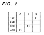
- the individual gear stages 1ST, 2ND, 3RD and 4TH of 1st to 4th speeds are achieved by supplying/releasing the oil pressure to the hydraulic servos corresponding to the individual engaging elements under the control of the not-shown hydraulic control system including the aforementioned supply circuit, to applying (as indicated by symbols ⁇ ) and releasing (as indicated by no sign) the individual engaging elements A, B and C, as tabulated in Fig. 2.
- the other engaging element correspond in the present embodiment to the engaging element A to be applied for achieving the 4th speed (4TH)
- the band brake to which is applied the present invention, corresponds to the engaging element C to be applied for achieving the 1st speed (1ST).
- the engaging element A is applied when an apply pressure (P A ) is supplied from the supply circuit L to the hydraulic servo 4 of the engaging element A, as shown in Fig. 1, to achieve the 4th speed (4TH).
- This oil pressure is also supplied by way of the oil passage 4 and the release oil passage L R to the return oil chamber R R of the hydraulic servo 1 so that the first piston 12 is pushed back by that pressure while compressing the separate spring 14 thereby to push back the rod 11 fixed thereon to the shown retracted position.
- the band 3 is radially enlarged following the retraction of the rod 11 by its own expanding force thereby to enlarge a clearance G from the drum 2 to a width (e.g., about 1 mm) sufficient for establishing no dragging resistance of the oil.
- a width e.g., about 1 mm
- the apply pressure of the hydraulic servo 4 is released, and the oil pressure, as supplied to the return oil chamber R R of the hydraulic servo 1, is also released via the release oil passage L R .
- the first piston 12 is released from its received pressure and is pushed out by the load of the separate spring 14 so that the rod 11 fixed thereon is returned to a standby position.
- the band 3 is radially reduced by the push of the rod against its own expanding force to reduce the clearance G to the value (e.g., about 0.5 mm) corresponding to the released state of the prior art so that it comes to the standby position for the shift to the 1st speed.
- the oil pressure is not originally supplied to the supply circuit L so that the first piston is pushed to the standby position by the load of the separate spring 14.
- the state as shown in the uppermost stage of Fig. 3, illustrates the retracted position of the rod 11, and the oil pressure is supplied (as indicated by downward arrow in Fig. 3) only to the return oil chamber R R .
- both the first and second pistons 12 and 13 are in the most retracted position with respect to the band, and the rod 11 is also in the retracted position with respect to the second piston 13.
- the separate spring 14 is also compressed.
- This state is the aforementioned retracted position, as indicated by S R in Fig. 3.
- the second piston 13 advances while compressing the return spring 15 until the band comes into engagement with the drum to stop the advance of the rod 11.
- the rod 11, the first piston 12 and the second piston 13 are displaced exclusively in their positions while leaving all their relative positional relations and the compressed state of the separate spring 14 similar to those of the standby state.
- the band comes into contact with the drum to eliminate the clearance G (as shown in Fig. 1) thereby to stop the advance of the rod 11, the second piston 13 then continues its further advance while compressing the separate spring 14, too.
- the reaction load by the compression of the separate spring 14 through the first piston 12 is applied to the rod 11 so that the force, as damped by the spring elasticity of the spring 14, is applied to the band thereby to provide an effect to damp the shocks at the beginning of the brake application.
- the automatic transmission is enabled to achieve the 1st speed, i.e., the first gear stage to be established by applying the band brake, the 2nd speed, i.e., the second gear stage close to the first gear stage, and the 4th speed, i.e., the third gear stage interposing the 2nd speed between itself and the 1st speed and higher than the 1st and 2nd speeds.
- the rod 11 of the hydraulic servo is set to the apply position for establishing the 1st sped, to the standby position at the 2nd speed, and to the retracted position at the 4th speed.
- the hydraulic servo 1 is constructed to have the apply oil chamber R A to be supplied with the oil pressure for pushing the rod 11 in the apply direction, and the return oil chamber R R to be fed with the oil pressure for pushing the same in the release direction.
- the rod 11 is set to the apply position by supplying the oil pressure to the apply oil chamber R A , to the standby position by releasing the oil pressure from the return oil chamber R R and the apply oil chamber R A , and to the retracted position by supplying the oil pressure to the return oil chamber R R .
- the hydraulic servo 1 is constructed to include: the first piston 12 fixed immovably on the rod 11 and fitted movably in the cylinder 10 of the hydraulic servo 1; the second piston 13 supported by the rod 11 to slide axially by a predetermined extend and fitted movably in the cylinder for defining the apply oil chamber R A with the cylinder 10; the separate spring 14 for separating those pistons in the axial direction from each other; and the return spring 15 for urging the second piston 13 in the release direction.
- the oil pressure to be supplied to the return oil chamber R R is that of the other hydraulic servo 4 for the engaging element A to be applied for achieving the 4th speed.
- the selection can be made between the standby position, in which the rod 11 is not relatively retracted, and the retracted position, in which the rod 11 is largely retracted, so that the rod is set in advance in the standby position when the band brake may probably be applied, to cause no drop in the application response.
- the dragging loss can be reduced by setting the rod in the retracted position in which the rod is located at the back of the standby position.
- the shift is highly probably made to the 1st speed to apply the brake, and at the 3rd or 4th speed, the shift is made to the 1st speed ordinarily through the 2nd speed.
- the state of high probability of application can be easily discriminated without any use of special detection means, so that the drop in the application response can be prevented without fail.
- the running frequency is high, and the influence upon the mileage due to the dragging loss is also high so that the mileage can be effectively improved by setting the rod 11 at the release position at the high-speed stage.
- the position of the rod 11 is changed so that the hydraulic servo-mechanism can be given a compact construction by the simple circuit construction.
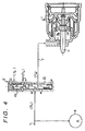
- Fig. 4 shows a second mode of embodiment of the present invention.
- This embodiment is similar to the foregoing first embodiment in that the rod is retracted at the 4th speed but is different in that the rod is returned to the standby position for making preparations for the kickdown of the driver of the vehicle.
- a change-over valve 5 is disposed in the oil passage r.
- This change-over valve 5 is a spring return type valve, as constructed to include: a spool 51 for switching the connection of the release oil passage r with the drain by providing/blocking the communication of the supply circuit L with the release oil passage r; and a plunger 52 for causing the spool 51 to switch, as described above.
- the plunger 52 can be supplied with a 2-range (or second range) pressure (P 2 ) of the hydraulic circuit to set the hydraulic servo 1 in the standby position at the 2nd speed establishing time, and the spool 51 can be supplied irrespective of its position with a throttle pressure (P th )
- the throttle pressure (P th ) is outputted from the not-shown throttle valve of the hydraulic circuit so that the spool 51 of the change-over valve 5 is switched to the position, as indicated at the righthand half of Fig. 4, to close the supply circuit L and to connect the release oil passage 4 to the drain.
- the oil pressure of the return oil chamber R R is released so that the first piston 12 is pushed out by the load of the separate spring 14 to bring the rod 11 into the standby position.
- the 4th speed (4TH) or the third gear stage is set at a higher side than the 1st speed (1ST) or the first gear stage and the 2nd speed (2ND) or the second gear stage, and the return oil chamber R R is connected via the oil passage 4 to the other hydraulic servo 4 for the engaging ele ment A to be applied for establishing the 3rd gear stage (4TH).
- this oil passage 4 there is arranged the valve 5 for blocking the oil passage 4 when the throttle opening exceeds a predetermined value.
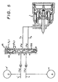
- Fig. 5 shows a third mode of embodiment of the present invention.
- This embodiment is similar to the foregoing second embodiment in that the rod is returned to the standby position to make preparations for the kick-down operation but is difference from any of the foregoing embodiments in that the rod is also retracted at the 3rd speed.
- both the supply circuits L and L' of the engaging elements A and B are switched according to the aforementioned gist of the present invention.
- two check valves as shown, are provided for preventing the communication between the two hydraulic servos 4 and 4'.
- the time period for setting the standby position for causing the dragging loss can be limited to the minimum, and a brake application can be achieved in quick response to a shift skipping an intermediate gear stage such as the kick-down shift.
- the 4th speed (4TH) and the 3rd speed (3RD) correspond to the third gear stage of the present invention.
- the present invention is applied to the single-wound band brake but could be applied to the structure in which the band is doubly wound on the drum.
- the retraction stroke required for the rod of the hydraulic servo is about two times as large as that of the single-wound band brake in order to establish the predetermined clearance between the drum and the band. Therefore, the effect of the rod retraction by applying the present invention becomes far more prominent.
- the rod in the unapplied state of the band brake, the rod can be selectively set to the standby position, in which it is less retracted, and the retracted position in which it is more retracted.
- the rod is set in advance in the standby position when the probability of application of the band brake is high, the application response is not dropped.
- the rod is set to the retracted position in which it is more retracted than the standby position when the probability of the application is low, the dragging loss can be reduced.
- the rod position in accordance with the application probability, the dragging loss at the releasing time can be reduced as much as possible without lowering the application response.
- the speed change may probably be made to the first gear stage at the time of establishing the second gear stage close to the first gear stage, and the shift is ordinarily made to the first gear stage through the second gear stage at the time of establishing the third gear stage.
- the state of high probability of application can be easily discriminated by causing the set position of the rod of the hydraulic servo to each gear stage, and the reduction of the application response can be reliably prevented by holding the rod in the standby position at the time of establishing the second gear stage.
- the mileage can be effectively improved by setting the rod to the released position at a high gear stage in which the influence of the dragging loss upon the mileage is serious.
- the rod setting position can be altered merely by supplying the oil pressure selectively in the opposite direction to the hydraulic servo, so that hydraulic servo can be given a simple and compact construction.
- the pushing force to be applied to the rod of the hydraulic servo in the brake applying direction can be damped to the brake applying force by the separate spring so that the application shocks can be reduced without any special control of the oil pressure to be fed to the hydraulic servo.
- the rod can be set to the retracted position by the simple circuit construction.
- the band by supporting the band on the anchor pin and the case by its own expanding force at the time of releasing the band brake, the band can be held, even if deformed, at a uniform clearance all over the circumference from the drum.
- the predetermined gap is established between the apply side bracket and the leading end portion of the rod of the hydraulic servo so that the band is supported on the anchor pin and the case by the sufficient holding force of its own expanding force without being obstructed by the leading end portion of the rod, thereby to cause no interference between the band and the drum by the vibrations or the like.
Landscapes
- Engineering & Computer Science (AREA)
- General Engineering & Computer Science (AREA)
- Mechanical Engineering (AREA)
- Braking Arrangements (AREA)
- Gear-Shifting Mechanisms (AREA)
- Actuator (AREA)
Applications Claiming Priority (2)
| Application Number | Priority Date | Filing Date | Title |
|---|---|---|---|
| JP46940/96 | 1996-02-09 | ||
| JP8046940A JPH09217765A (ja) | 1996-02-09 | 1996-02-09 | 自動変速機の油圧サーボ装置 |
Publications (2)
| Publication Number | Publication Date |
|---|---|
| EP0789172A2 true EP0789172A2 (de) | 1997-08-13 |
| EP0789172A3 EP0789172A3 (de) | 1998-06-17 |
Family
ID=12761321
Family Applications (1)
| Application Number | Title | Priority Date | Filing Date |
|---|---|---|---|
| EP96119369A Withdrawn EP0789172A3 (de) | 1996-02-09 | 1996-12-03 | Hydraulische Servoeinrichtung für Automatikgetriebe |
Country Status (3)
| Country | Link |
|---|---|
| US (1) | US5881858A (de) |
| EP (1) | EP0789172A3 (de) |
| JP (1) | JPH09217765A (de) |
Cited By (1)
| Publication number | Priority date | Publication date | Assignee | Title |
|---|---|---|---|---|
| CN103154553A (zh) * | 2010-09-23 | 2013-06-12 | 舍弗勒技术股份两合公司 | 用于行星齿轮变速器的缠绕式制动装置和具有缠绕式制动装置的行星齿轮变速器 |
Families Citing this family (3)
| Publication number | Priority date | Publication date | Assignee | Title |
|---|---|---|---|---|
| JP4019554B2 (ja) | 1998-08-03 | 2007-12-12 | トヨタ自動車株式会社 | 燃料電池セパレータ用多連凹凸板の製造方法 |
| US6357560B1 (en) * | 2000-03-21 | 2002-03-19 | Ford Global Tech., Inc. | Servo assembly for operating a brake band in an automatic transmission vehicle |
| US7066305B2 (en) * | 2000-12-08 | 2006-06-27 | Borgwarner Inc. | Brake bands for an automatic transmission and method for controlling a gear shift in automatic transmission and feedback loop control system |
Citations (1)
| Publication number | Priority date | Publication date | Assignee | Title |
|---|---|---|---|---|
| US4787494A (en) | 1983-03-31 | 1988-11-29 | Aisin Seiki Kabushiki Kaisha | Hydraulic operating unit of friction engaging apparatus for transmissions |
Family Cites Families (17)
| Publication number | Priority date | Publication date | Assignee | Title |
|---|---|---|---|---|
| US2227245A (en) * | 1932-04-28 | 1940-12-31 | Bendix Aviat Corp | Brake |
| US2193305A (en) * | 1937-08-21 | 1940-03-12 | Gen Motors Corp | Brake and clutch capacity control |
| US2513192A (en) * | 1948-03-18 | 1950-06-27 | Packard Motor Car Co | Multiple piston hydraulic motor for planetary gear brakes |
| US2769307A (en) * | 1950-07-14 | 1956-11-06 | Studebaker Packard Corp | Hydraulically operated servo-motor |
| US2633712A (en) * | 1951-02-16 | 1953-04-07 | Chrysler Corp | Servo cylinder |
| DE1198216B (de) * | 1957-07-26 | 1965-08-05 | Daimler Benz Ag | Schaltvorrichtung fuer insbesondere in Kraftfahrzeugen verwendbare Geschwindigkeitswechselgetriebe, die als durch OEldruck mittels Steuerorgane kraftschluessig schaltbare Umlaufraedergetriebe ausgebildet sind |
| US2901888A (en) * | 1957-09-20 | 1959-09-01 | Int Harvester Co | Multi-piston servo-motor |
| US3353637A (en) * | 1965-10-22 | 1967-11-21 | Gen Motors Corp | Servo motor |
| GB1336710A (en) * | 1970-11-05 | 1973-11-07 | Automotive Prod Co Ltd | Fluid pressure operable actuators |
| JPS6114697Y2 (de) * | 1980-06-04 | 1986-05-08 | ||
| US4456100A (en) * | 1981-08-04 | 1984-06-26 | Kabushiki Kaisha Daikin Seisakusho | Band brake mechanism for an automatic transmission of an automobile |
| JPS6084452A (ja) * | 1983-10-14 | 1985-05-13 | Nissan Motor Co Ltd | アキユムレ−タ内蔵油圧サ−ボ装置 |
| JPH0663556B2 (ja) * | 1985-09-30 | 1994-08-22 | アイシン・エィ・ダブリュ株式会社 | 4輪駆動車の自動変速機 |
| US4930373A (en) * | 1987-12-04 | 1990-06-05 | Toyota Jidosha Kabushiki Kaisha | Brake system for automatic transmission |
| JP3103568B2 (ja) * | 1989-06-29 | 2000-10-30 | アイシン・エィ・ダブリュ株式会社 | 自動変速機における油圧制御装置 |
| US5588928A (en) * | 1995-05-08 | 1996-12-31 | Koivunen; Erkki A. | Self-synchronizing brake band actuating system for automatic change speed transmissions |
| US5711403A (en) * | 1996-11-04 | 1998-01-27 | Ford Global Technologies, Inc. | Rapid apply servo for a brake band of an automatic transmission |
-
1996
- 1996-02-09 JP JP8046940A patent/JPH09217765A/ja active Pending
- 1996-12-03 EP EP96119369A patent/EP0789172A3/de not_active Withdrawn
- 1996-12-27 US US08/777,179 patent/US5881858A/en not_active Expired - Lifetime
Patent Citations (1)
| Publication number | Priority date | Publication date | Assignee | Title |
|---|---|---|---|---|
| US4787494A (en) | 1983-03-31 | 1988-11-29 | Aisin Seiki Kabushiki Kaisha | Hydraulic operating unit of friction engaging apparatus for transmissions |
Cited By (2)
| Publication number | Priority date | Publication date | Assignee | Title |
|---|---|---|---|---|
| CN103154553A (zh) * | 2010-09-23 | 2013-06-12 | 舍弗勒技术股份两合公司 | 用于行星齿轮变速器的缠绕式制动装置和具有缠绕式制动装置的行星齿轮变速器 |
| CN103154553B (zh) * | 2010-09-23 | 2016-10-05 | 舍弗勒技术股份两合公司 | 用于行星齿轮变速器的缠绕式制动装置及行星齿轮变速器 |
Also Published As
| Publication number | Publication date |
|---|---|
| EP0789172A3 (de) | 1998-06-17 |
| JPH09217765A (ja) | 1997-08-19 |
| US5881858A (en) | 1999-03-16 |
Similar Documents
| Publication | Publication Date | Title |
|---|---|---|
| KR100293877B1 (ko) | 자동변속기용회전클러치장치 | |
| US6270444B1 (en) | Shift control apparatus for automatic transmission | |
| EP2122203B1 (de) | Hydraulische steuervorrichtung und hydraulisches steuerverfahren für ein automatikgetriebe | |
| US4547178A (en) | Control system for an automatic transmission for a vehicle | |
| US4930373A (en) | Brake system for automatic transmission | |
| US6099429A (en) | Method and systems for improving the operation of transmission for motor vehicles | |
| EP0138201B1 (de) | Hydraulische Servovorrichtung mit eingebautem Speicher | |
| EP0577174B1 (de) | Einrichtung zur Kraftübertragung | |
| US5881858A (en) | Hydraulic servo-mechanism for an automatic transmission | |
| EP0330408A2 (de) | Hydraulische Steuervorrichtung für automatische Getriebe | |
| KR20020063809A (ko) | 자동 변속기의 예비충전 제어 시스템 | |
| US5411451A (en) | Control system for controlling the pressure of the oncoming servo hydraulic pressure based on a predicted time to sync from output shaft acceleration in automatic transmission | |
| US5138906A (en) | Shift control system, and process for automatic transmissions | |
| US5403248A (en) | Control system for changing servo timings of hydraulic pressure based on a torque input in automatic transmission | |
| JPS6081550A (ja) | 自動変速機の油圧制御装置 | |
| US4676349A (en) | Fluid pressure control system having a pressure cutback device | |
| EP1188967A3 (de) | Schaltsteuerung für ein automatisches Getriebe | |
| US6220402B1 (en) | Hydraulic servo apparatus for automatic transmission | |
| US5492028A (en) | Trimmer valve with flow retention | |
| JP2646863B2 (ja) | 変速機の油圧制御装置 | |
| JP3659442B2 (ja) | 油圧サーボ装置 | |
| JP3543651B2 (ja) | 自動変速機の変速制御装置 | |
| JPH0582511B2 (de) | ||
| KR100220058B1 (ko) | 자동차용 4속 자동변속기의 유압 제어 시스템 | |
| JPH05272631A (ja) | 自動変速機の変速制御装置 |
Legal Events
| Date | Code | Title | Description |
|---|---|---|---|
| PUAI | Public reference made under article 153(3) epc to a published international application that has entered the european phase |
Free format text: ORIGINAL CODE: 0009012 |
|
| 17P | Request for examination filed |
Effective date: 19961231 |
|
| AK | Designated contracting states |
Kind code of ref document: A2 Designated state(s): DE GB |
|
| PUAL | Search report despatched |
Free format text: ORIGINAL CODE: 0009013 |
|
| RHK1 | Main classification (correction) |
Ipc: F16H 63/30 |
|
| AK | Designated contracting states |
Kind code of ref document: A3 Designated state(s): DE GB |
|
| 17Q | First examination report despatched |
Effective date: 20000717 |
|
| GRAH | Despatch of communication of intention to grant a patent |
Free format text: ORIGINAL CODE: EPIDOS IGRA |
|
| RTI1 | Title (correction) |
Free format text: AUTOMATIC TRANSMISSION WITH HYDRAULIC SERVO DEVICE |
|
| STAA | Information on the status of an ep patent application or granted ep patent |
Free format text: STATUS: THE APPLICATION IS DEEMED TO BE WITHDRAWN |
|
| 18D | Application deemed to be withdrawn |
Effective date: 20030603 |