EP0788976B1 - Behälter und hitzebeständiger Behälterverschluss - Google Patents
Behälter und hitzebeständiger Behälterverschluss Download PDFInfo
- Publication number
- EP0788976B1 EP0788976B1 EP97101824A EP97101824A EP0788976B1 EP 0788976 B1 EP0788976 B1 EP 0788976B1 EP 97101824 A EP97101824 A EP 97101824A EP 97101824 A EP97101824 A EP 97101824A EP 0788976 B1 EP0788976 B1 EP 0788976B1
- Authority
- EP
- European Patent Office
- Prior art keywords
- container
- tube
- ridge
- heat
- intermediate tube
- Prior art date
- Legal status (The legal status is an assumption and is not a legal conclusion. Google has not performed a legal analysis and makes no representation as to the accuracy of the status listed.)
- Expired - Lifetime
Links
Images


Classifications
-
- B—PERFORMING OPERATIONS; TRANSPORTING
- B65—CONVEYING; PACKING; STORING; HANDLING THIN OR FILAMENTARY MATERIAL
- B65D—CONTAINERS FOR STORAGE OR TRANSPORT OF ARTICLES OR MATERIALS, e.g. BAGS, BARRELS, BOTTLES, BOXES, CANS, CARTONS, CRATES, DRUMS, JARS, TANKS, HOPPERS, FORWARDING CONTAINERS; ACCESSORIES, CLOSURES, OR FITTINGS THEREFOR; PACKAGING ELEMENTS; PACKAGES
- B65D41/00—Caps, e.g. crown caps or crown seals, i.e. members having parts arranged for engagement with the external periphery of a neck or wall defining a pouring opening or discharge aperture; Protective cap-like covers for closure members, e.g. decorative covers of metal foil or paper
- B65D41/32—Caps or cap-like covers with lines of weakness, tearing-strips, tags, or like opening or removal devices, e.g. to facilitate formation of pouring openings
- B65D41/46—Snap-on caps or cap-like covers
- B65D41/48—Snap-on caps or cap-like covers non-metallic, e.g. made of paper or plastics
- B65D41/485—Snap-on caps or cap-like covers non-metallic, e.g. made of paper or plastics with integral internal sealing means
-
- B—PERFORMING OPERATIONS; TRANSPORTING
- B65—CONVEYING; PACKING; STORING; HANDLING THIN OR FILAMENTARY MATERIAL
- B65D—CONTAINERS FOR STORAGE OR TRANSPORT OF ARTICLES OR MATERIALS, e.g. BAGS, BARRELS, BOTTLES, BOXES, CANS, CARTONS, CRATES, DRUMS, JARS, TANKS, HOPPERS, FORWARDING CONTAINERS; ACCESSORIES, CLOSURES, OR FITTINGS THEREFOR; PACKAGING ELEMENTS; PACKAGES
- B65D47/00—Closures with filling and discharging, or with discharging, devices
- B65D47/04—Closures with discharging devices other than pumps
- B65D47/06—Closures with discharging devices other than pumps with pouring spouts or tubes; with discharge nozzles or passages
- B65D47/08—Closures with discharging devices other than pumps with pouring spouts or tubes; with discharge nozzles or passages having articulated or hinged closures
- B65D47/0857—Closures with discharging devices other than pumps with pouring spouts or tubes; with discharge nozzles or passages having articulated or hinged closures made separately from the base element provided with the spout or discharge passage
-
- B—PERFORMING OPERATIONS; TRANSPORTING
- B65—CONVEYING; PACKING; STORING; HANDLING THIN OR FILAMENTARY MATERIAL
- B65D—CONTAINERS FOR STORAGE OR TRANSPORT OF ARTICLES OR MATERIALS, e.g. BAGS, BARRELS, BOTTLES, BOXES, CANS, CARTONS, CRATES, DRUMS, JARS, TANKS, HOPPERS, FORWARDING CONTAINERS; ACCESSORIES, CLOSURES, OR FITTINGS THEREFOR; PACKAGING ELEMENTS; PACKAGES
- B65D47/00—Closures with filling and discharging, or with discharging, devices
- B65D47/04—Closures with discharging devices other than pumps
- B65D47/06—Closures with discharging devices other than pumps with pouring spouts or tubes; with discharge nozzles or passages
- B65D47/10—Closures with discharging devices other than pumps with pouring spouts or tubes; with discharge nozzles or passages having frangible closures
- B65D47/103—Membranes with a tearing element
Definitions
- the present invention relates to a container for containing juice, alcoholic drink, soup or the like that is heated when filled in the container, and a heat-resistant cap for use with the container.
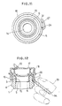
- Fig. 13 denoted by reference numeral 51 is a container illustrated as, by way of example, a bottle.
- the container 51 has a mouth 52 provided with an annular recess 53 formed in an outer circumferential surface of its upper portion and an annular boss 54 formed below the annular recess 53.
- Denoted by 55 is an intermediate stopper made of synthetic resin, e.g., polyethylene, and comprising an inner tube 56, an intermediate tube 57 and an upper wall 58.
- a mouth wall 60 having an endless rippable groove 59 formed therein is provided at the center.
- the intermediate stopper 55 also comprises a ripping member 61, a lower support portion 62, a pouring tube 63 and a latching portion 64.
- Denoted by 65 is an annular ridge engaging the annular recess 53.
- denoted by 66 is an outer lid made of highly heat-resistant synthetic resin, e.g., polypropylene, and comprising an outer tube 67 and a lid member 68 formed integrally with each other through a hinge 69.
- the outer tube 67 has a lower end 70 positioned to rest on an upper end of the lower support portion 62, and also has an annular engagement portion 71 formed on an inner circumferential surface of its upper portion to project radially inward.
- the engagement portion 71 is engaged in vertical relation with the latching portion 64 annularly formed above the upper wall 58 of the intermediate stopper 55.
- the lid member 68 is held in place such that a locked portion 72 formed in a part of an inner circumferential surface of the lid member is lightly locked in vertical relation by a locking portion 73 formed in an upper part of the engagement portion 71 when the lid member is closed.
- denoted by 74 is an annular intermediate leg coming into close contact with the pouring tube 63.
- the container and the heat-resistant cap for use with the container are suitably employed to contain liquid goods as mentioned above which are heated when filled in the container.
- the outer tube 67 made of heat-resistant synthetic resin and held in pressure contact with the intermediate tube 57 serves to prevent the intermediate tube 57 from reducing elasticity, i.e., losing a proper elastic deformation, due to heat transmitted through the mouth 52 from a heated liquid (not shown) filled in the container 51, and hence to compensate for a reduction in degree of sealing.
- the container 51 is prevented from lowering a degree of sealing by the presence of the outer tube 67.
- the heat-resistant cap When the liquid commodity in the container 51 is used up and the container 51 is recovered for recycling of resources, it is required to separate the container 51 and the heat-resistant cap from each other. Stated otherwise, the heat-resistant cap must be removed from the container mouth 52. However, the heat-resistant cap cannot be easily removed from the container mouth 52 because the ridge 65 of the intermediate tube 57 is tightly engaged in vertical relation with the recess 53 of the mouth 52. Also, even in an attempt to remove the heat-resistant cap by using an uncapping tool such as a cap opener, the use of an uncapping tool such as a cap opener will be in vain because an access to a lower end of the lower support portion 62 is blocked off by the boss 54 of the container mouth 52.
- the present invention has been made with a view of solving the problem stated above, and its object is to provide a container and a heat-resistant cap for use with the container, which heat-resistant cap is of hit-capping type that can be easily fitted to the container by simple hitting when capped over a mouth of the container, and can also be very easily removed from the container mouth, and which container is suitable for recycling of resources.
- the lower end of the outer tube is located in a position corresponding to the upper edge of the ridge of the intermediate tube, and the embrittled line is formed in the inner circumferential surface of the intermediate tube in a position contiguous to the upper edge of the ridge.
- the lower end of the outer tube is located in a position corresponding to the upper edge of the ridge of the intermediate tube, and the embrittled line is formed in the inner circumferential surface of the intermediate tube in a position contiguous to the lower edge of the ridge.
- the lower end of the outer tube is located in a position corresponding to the ridge of the intermediate tube, and the embrittled line is formed in the inner circumferential surface of the intermediate tube in a position contiguous to the lower edge of the ridge.
- the embrittled portion is formed in the form of a slit.
- the lower end of the outer tube is located in a position corresponding to substantially the lower edge of the ridge of the intermediate tube, and a part of the intermediate tube below an upper end of the lower support portion is formed to be dislocated radially outward of the remaining part thereof to form an embrittled line in the dislocated position.
- the ridge is held in pressure contact with the recess in the vertical direction by the lower end of the outer tube.
- the ridge is located in a position above a bottom portion of the recess.
- the outer tube and the lid member are joined to each other through a hinge.
- the lower support portion includes a tab provided contiguous to or in the vicinity of the embrittled portion.
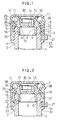
- Fig. 1 is cross-sectional view, partly omitted, of a container and a heat-resistant cap for use with the container, the view showing a first embodiment of the present invention and a state where the cap is fitted to the container.
- Fig. 2 is cross-sectional view similar to Fig. 1, the view showing a second embodiment of the present invention.
- Fig. 3 is cross-sectional view similar to Fig. 1, the view showing a third embodiment of the present invention.
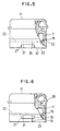
- Fig. 4 is a side view, partly sectioned, of the heat -resistant cap shown in Fig. 1.
- Fig. 5 is a side view, partly sectioned, of a heat-resistant cap shown in Fig. 3.
- Fig. 6 is a side view, partly sectioned, of a heat-resistant cap, the view showing a fourth embodiment of the present invention.
- Fig. 7 is a side view, partly sectioned, of a heat-resistant cap, the view showing a fifth embodiment of the present invention.
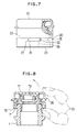
- Fig. 8 is a view showing a state where the heat-resistant cap shown in Fig. 1 is being removed from the container.
- Fig. 9 is a view showing a state where a heat-resistant cap shown in Fig. 2 is being removed from a container.
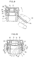
- Fig. 10 is cross-sectional view, partly omitted, of a container and a heat-resistant cap for use with the container, the view showing a sixth embodiment of the present invention and a state where the cap is fitted to the container.
- Fig. 11 is a bottom view of the heat-resistant cap shown in Fig. 10.
- Fig. 12 is a view showing a state where the heat-resistant cap shown in Fig. 10 is being removed from the container.
- Fig. 13 is cross-sectional view, partly omitted, of a conventional container and a conventional heat-resistant cap for use with the container.
- the container 1 has a mouth 2 provided in its outer circumferential surface with an annular recess 3 and an annular boss 4 formed in the order named from above with a spacing therebetween.
- Denoted by 5 is a stopper fitted over the mouth 2 and made of synthetic resin, e.g., polyethylene.
- the stopper 5 has a gripping portion 9 comprising an inner tube 6, an intermediate tube 7 and an upper wall 8. The gripping portion 9 grips the mouth 2 in such a manner that the inner tube 6, the intermediate tube 7 and the upper wall 8 are held in pressure contact with inner, outer and top surfaces of the mouth 2, respectively, thereby keeping the stopper 5 fitted over the mouth 2.
- Denoted by 10 is a pouring tube extending upward from the upper wall 8, and a mouth wall 14 having an endless rippable groove 12 formed therein is provided integrally with the upper wall 8 and within the pouring tube 10.
- the mouth wall 14 includes a ripping member 13 in the form of a pull ring provided inside the rippable groove 12.
- the intermediate tube 7 has an annular ridge 15 formed on its inner circumferential surface. When the heat-resistant cap is capped over the mouth 2 of the container by hitting, the annular ridge 15 is engaged with the annular recess 3 formed in the outer circumferential surface of the mouth 2 in its upper end portion.
- Denoted by 11 is a latching portion formed above the upper wall 8 to extend radially outward and engaged with an engagement portion 19 of an outer lid 18, described later, for latching the same.
- denoted by 18 is an outer lid made of synthetic resin, e.g., polypropylene, having a softening temperature against heat that is higher than not only the softening temperature of the synthetic resin as material of the stopper 5, but also the boiling point of water, and having hardness higher than the material of the stopper 5.
- the outer lid 18 comprises an outer tube 16 held in pressure contact with an outer circumferential surface of the intermediate tube 7 and a lid member 17.
- the outer tube 16 and the lid member 17 are integrally formed with each other through a hinge 26.
- the outer tube 16 has an annular engagement portion 19 formed on an inner circumferential surface of its upper part and, as seen from the drawing, the engagement portion 19 is engaged in vertical relation with the latching portion 11 annularly formed above the upper wall 8 of the intermediate stopper 5.
- the outer tube 16 has a lower end 20 located around the intermediate tube 7 in a position corresponding to any one of upper and lower edges and a middle point of the ridge 15 on the inner circumferential surface of the intermediate tube 7. More specifically, the lower end 20 of the outer tube 16 is positioned corresponding to the upper edge of the ridge 15 in the first and second embodiments shown in Figs. 1 and 2, while it is positioned corresponding to substantially the middle point of the ridge 15 in the third embodiment shown in Fig. 3.
- the lower end 20 of the outer tube 16 located in any of the above positions can serve to urge the ridge 15 toward the mouth 2 for pressure contact therewith.
- Denoted by 28 is a locked portion and 29 is a locking portion, the former 28 being lightly locked in vertical relation by the latter 29 when the lid member 17 is closed.
- the intermediate tube 7 has an embrittled line 22 formed therein contiguous to any one of the upper and lower edges of the ridge 15.
- the embrittled line 22 is formed as a thin-walled portion, for example, and may be formed entirely or partly over the circumference of the intermediate tube 7. In the first embodiment shown in Fig. 1, the embrittled line 22 is formed contiguous to the upper edge of the ridge 15, while in the second and third embodiments shown in Figs. 2 and 3, it is formed contiguous to the lower edge of the ridge 15. Note that the embrittled line 22 may be in the form of perforations, successive holes or notches, or combinations thereof other than the thin-walled portion.
- denoted by 30 is an annular intermediate leg formed on an inner surface of the lid member 17 and coming into close contact with the pouring tube 10 when the outer lid 18 is closed.
- an embrittled portion formed as a thin-walled portion, for example, to extend from a lower end 23 of the intermediate tube 7 to the embrittled line 22.
- the embrittled portion 24 may be in the form of perforations, successive holes or notches, or combinations thereof other than the thin-walled portion.
- the embrittled portion 24 may be in the form of a slit as shown in Fig. 6.
- the intermediate tube 7 also includes a tab 27 provided on its outer circumferential surface near the embrittled portion 22. When the tab 27 is pulled, a part of the intermediate tube is ripped off along the embrittled portion 24 and the embrittled line 22.
- 31 is a connecting piece formed to be easily rippable
- 32 is a secured portion ofthe connecting piece 31.
- the outer tube 16 of the outer lid 18, which is made of synthetic resin having a softening temperature against heat that is higher than not only the softening temperature of the material of the intermediate tube 7, but also the boiling point of water, and having hardness higher than the material of the intermediatetube 7, is held in pressure contact with the outer circumferential surface of the intermediate tube 7, such a reduction in strength of the pressure contact of the intermediate tube 7 is compensated by the pressure contact of the outer tube 16. As a result, a reduction in degree of sealing can be kept within a practically allowable range.
- a cap of another embodiment such as shown in Fig. 10 also operates in the same manner as described above.
- Denoted by 21 is a lower support portion.
- the embrittled portion 24 of the intermediate tube 7 and then the embrittled line 22 connecting to the former are ripped up.
- the embrittled line 22 is formed contiguous to selected one of the upper and lower edges of the ridge 15, the intermediate tube 7 is ripped up circumferentially at the upper or lower edge of th e ridge 15.
- the lower end 20 of the outer tube 16 is not extended to reach the lower end 23 of the intermediate tube 7, but it is terminated in a position adjacent to the ridge 15.
- the outer tube 16 can serve to press the ridge 15 inward on one hand, and allows the intermediate tube 16 to be ripped up along the embrittled line 22 in spite of the presence of itself on the other hand.
- the intermediate tube 16 may be ripped up completely when the embrittled line 22 is formed all over the circumference thereof, or partly when it is formed over a part of the circumference thereof.
- the embrittled line 22 is formed contiguous to the upper edge of the ridge 15
- forces urging the ridge 15 into the pressure contact state are weakened by partly ripping up the intermediate tube 7 along the embrittled line, or are completely eliminated by ripping up same all over the circumference thereof.
- the heat-resistant cap can be easily removed from the mouth by placing a finger 33 against the ripped-up edge of the intermediate tube 7 and pushing it upward, as shown in Fig. 8.
- the heat-resistant cap can be easily removed from the mouth by placing an uncapping tool 34 such as a cap opener against the ripped-up edge of the intermediate tube 7 and pushing it upward, as shown in Fig. 9.
- an uncapping tool 34 such as a cap opener against the ripped-up edge of the intermediate tube 7 and pushing it upward, as shown in Fig. 9.
- the ripping-up can be more easily started by the presence of the tab 27 provided contiguous to or in the vicinity of the embrittled portion 24 as shown in Figs. 4 to 7. In other words, by gripping the tab 27 and pulling it outward, ripping forces can be easily applied to the embrittled portion 24.
- the cap when removing the heat-resistant cap from the container, the cap can be removed by placing the finger 33 or the uncapping tool such as a cap opener in contact with the outer lid 18 having higher hardness, i.e., rigidity, than the stopper 5, because the latching portion 11 of the stopper 5 is so tightly engaged with the engagement portion 19 of the outer tube 16 in its upper portion that the stopper 5 and the outer tube 16 are integrally fitted to each other over a wide circumferential region. Therefore, in comparison with the case of applying forces to a part of the relatively soft stopper 5 through direct dispersion of the forces due to a partial elastic deformation of the stopper 5 is less, thus enabling flexible and easy removal of the cap.
- the uncapping tool such as a cap opener
- a container and a heat-resistant cap for use with the container, shown in Fig. 10, according to a sixth embodiment of the present invention will be described below.
- a part of the intermediate tube 7 below an upper end of its lower support portion 21 is formed to be dislocated radially outward of the remaining part thereof,and the lower end 20 of the outer tube 16 is positioned substantially at the same level as the ridge 15.
- the outer circumferential surface of the mouth 2 includes a slope 35 extended from the recess 3 to the boss 4.
- the ridge 15 of the intermediate tube 7 is located midway the recess 3 in the vertical direction and is held in pressure contact with the recess 3 in a position above a bottom portion 25 of the recess 3.
- the container and the heat-resistant cap for use with the container which are constructed as described above, operate essentially in the same manner as with the other embodiments shown in Figs. 1 to 9.
- a liquid commodity filled in the container 1 can be used by opening the lid member 17, pulling the ripping member 13 and ripping off the mouth wall 14 along the rippable groove 12.
- the tab 27 is pulled so as to rip up the intermediate tube 7 along the embrittled portion 24 and then the embrittled line 22.
- the ripping-up causes the lower ends of the intermediate tube 7 and the outer tube 16 to appear substantially at the same level, as shown in Fig. 12.
- the heat-resistant cap can be easily removed from the container 1 by placing the uncapping tool 34 such as a cap opener against the lower ends of the intermediate tube 7 and the outer tube 16.
- the uncapping tool 34 such as a cap opener
- the cap can also be easily removed from the container 1 by applying forces directly with the finger 33.
- the heat-resistant cap of this embodiment since the part of the intermediate tube 7 below the upper end of the lower support portion 21 is formed to be dislocated radially outward of the remaining part thereof, ripping forces are concentrated on the outwardly dislocated portion when applied to rip up the intermediate tube 7 along the embrittled line 22, so that the intermediate tube 7 can be easily ripped up along the embrittled line 22. Also, since the ridge 15 of the intermediate tube 7 is located midway the recess 3 in the vertical direction, the heat-resistant cap can be more easily removed from the container 1 when uncapped.
- the heat-resistant cap when the heat-resistant cap is fitted to the mouth 2 of the container 1 filled with a heated liquid commodity, a reduction in degree of sealing due to heat of the liquid commodity transmitted through the mouth 2 can be kept within a practically allowable range. Also, when the container 1 is recovered for recycling of resources, the heat-resistant cap can be very easily removed from the mouth 2 of the container 1 by such a simple operation as ripping up the intermediate tube 7 along the embrittled portion 24 and then the embrittled line 22 connecting to the former.
- the heat-resistant cap can be very easily removed by the finger 33 without using the uncapping tool 34 such as a cap opener.
- the heat-resistant cap can be very easily removed by using the uncapping tool 34 such as a cap opener.
- the outer tube 16 can satisfactorily bring the ridge 15 of the intermediate tube 7 into pressure contact with the mouth 2, and the heat-resistant cap can be very easily removed by using the uncapping tool 34 such as a cap opener.
- the embrittled portion 24 is in the form of a slit, it is very easy to start ripping up the intermediate tube 7 along the embrittled line 22.
- the heat-resistant cap can be more easily removed from the mouth 2.
- the tab 27 is provided contiguous to or in the vicinity of the embrittled portion 24, the part of the intermediate tube 7 below the upper end of the lower support portion 21 can be easily ripped away along the embrittled line 22 by gripping the tab 27, although the intermediate tube 7 has a less grippable portion and is more hard to grip by the presence of the outer tube 16 held in pressure contact with the intermediate tube 7.
Landscapes
- Engineering & Computer Science (AREA)
- Mechanical Engineering (AREA)
- Closures For Containers (AREA)
- Packages (AREA)
- Details Of Rigid Or Semi-Rigid Containers (AREA)
Claims (10)
- Behälter und wärmebeständige Kappe zur Verwendung mit dem Behälter, aufweisend eine Eintiefung (3) und einen Vorsprung (4), die in und auf einer Außenumfangsfläche eines Mundstücks (2) eines Behälters (1) so gebildet sind, dass sie sich über den Umfang unter vertikalem Abstand untereinander erstrecken; einen Anschlag (5), der aus Kunstharz hergestellt ist und über dem Mundstück (2) angebracht ist; einen Griffabschnitt (9), der in dem Anschlag (5) vorgesehen ist, und ein Innenrohr (6), ein Zwischenrohr (7) und eine obere Wand (8) umfasst, die im Presskontakt mit Innen-, Außen- und Oberseiten des Mundstücks (2) gehalten sind; ein Gießrohr (10), das sich, ausgehend von der oberen Wand (8) und einem Verriegelungsabschnitt (11), erstreckt, der so gebildet ist, dass er sich radial auswärts von dem Gießabschnitt (10) erstreckt; eine Mundstückwand (14), die integral mit der oberen Wand (8) in dem Gießrohr (10) zum Verschließen des Mundstücks (2) vorgesehen ist, und ein Reißelement (13) in Form eines Zugrings umfasst, der über eine Oberseite der Mundstückwand (14) in einer Ringnut (12) von dieser gebildet ist, um die Mundstückwand (14) von der oberen Wand (8) entlang der Ringnut (12) zu trennen; eine Rippe (15), die auf der Außenumfangsfläche des Zwischenrohrs (7) vorgesehen ist und im Druckkontakt mit der Eintiefung (3) gehalten ist; einen Außendeckel (18) mit einem Außenrohr (16), der im Presskontakt mit einem Teil einer Außenumfangsfläche des Zwischenrohrs (7) gehalten ist, und mit einem Deckelelement (17), wobei der Außendeckel (18) aus Kunstharz hergestellt ist, der eine Erweichungstemperatur aufweist, die höher ist als sowohl die Erweichungstemperatur des Kunstharzes des Anschlags (5) als auch der Siedepunkt von Wasser, und mit einer höheren Härte als das Kunstharz des Anschlags (5); einen Eingriffabschnitt (19), der auf dem Außendeckel (18) vorgesehen ist und sich in vertikaler Beziehung zu dem Verriegelungsabschnitt (11) im Eingriff befindet; ein unteres Ende (20) des äußeren Rohrs (16), das um das Zwischenrohr (7) in einer Position entsprechend von einem der oberen und unteren Ränder und einem mittleren Bereich der Rippe (15) angeordnet ist; einen unteren Stützabschnitt (21), der in dem Zwischenrohr (7) zum Abstützen des unteren Endes (20) des Außenrohrs (16) vorgesehen ist; eine Versprödungslinie (22), die sich über den Umfang einer Innenumfangsfläche des Zwischenrohrs (7) in einer Position erstreckend gebildet ist, die sich an einen ausgewählten der oberen und unteren Ränder der Rippe (15) anschließt; und einen Versprödungsabschnitt (24), der so gebildet ist, dass er sich, ausgehend von einem unteren Ende (23) des Zwischenrohrs (7), zu der Versprödungslinie (22) erstreckt.
- Behälter und wärmebeständige Kappe zur Verwendung mit dem Behälter nach Anspruch 1, wobei das untere Ende (20) des Außenrohrs (16) in einer Position entsprechend dem oberen Rand der Rippe (15) des Zwischenrohrs (7) zu liegen kommt, und wobei die Versprödungslinie (22) in der Innenumfangsfläche des Zwischenrohrs (7) in einer Position gebildet ist, die sich an den oberen Rand der Rippe (15) anschließt.
- Behälter und wärmebeständige Kappe zur Verwendung mit dem Behälter nach Anspruch 1, wobei das untere Ende (20) des äußeren Rohrs (16) in einer Position entsprechend dem oberen Rand der Rippe (15) des Zwischenrohrs (7) zu liegen kommt, und wobei die Versprödungslinie (22) in der Innenumfangsfläche des Zwischenrohrs (7) in einer Position gebildet ist, die sich an den unteren Rand der Rippe (15) anschließt.
- Behälter und wärmebeständige Kappe zur Verwendung mit dem Behälter nach Anspruch 1, wobei das untere Ende (20) des Außenrohrs (16) in einer Position entsprechend der Rippe (15) des Zwischenrohrs (7) zu liegen kommt, und wobei die Versprödungslinie (22) in der Innenumfangsfläche des Zwischenrohrs (7) in einer Position zu liegen kommt, die sich an den unteren Rand der Rippe (15) anschließt.
- Behälter und wärmebeständige Kappe zur Verwendung mit dem Behälter nach einem der Ansprüche 1 bis 3, wobei der Versprödungsabschnitt (24) in Form eines Schlitzes gebildet ist.
- Behälter und wärmebeständige Kappe zur Verwendung mit dem Behälter nach Anspruch 1, wobei das untere Ende (20) des Außenrohrs (16) in einer Position entsprechend im Wesentlichen dem unteren Rand der Rippe (15) des Zwischenrohrs (7) zu liegen kommt, und wobei das Zwischenrohr (7) unterhalb eines oberen Endes des unteren Stützabschnitts (21) so gebildet ist, dass es radial auswärts von dem restlichen Teil von ihm zu liegen kommt, um eine Versprödungslinie (22) in der versetzten Position zu bilden.
- Behälter und wärmebeständige Kappe zur Verwendung mit dem Behälter nach Anspruch 6, wobei die Rippe (15) im Presskontakt mit der Eintiefung (3) in der vertikalen Richtung durch das untere Ende (20) des Außenrohrs (16) gehalten ist.
- Behälter und wärmebeständige Kappe zur Verwendung mit dem Behälter nach Anspruch 7, wobei die Rippe (15) in einer Position über einem Bodenabschnitt (25) der Eintiefung (3) zu liegen kommt.
- Behälter und wärmebeständige Kappe zur Verwendung mit dem Behälter nach einem der Ansprüche 1 bis 8, wobei das Außenrohr (16) und das Deckelelement (17) miteinander über ein Gelenk (26) verbunden sind.
- Behälter und wärmebeständige Kappe zur Verwendung mit dem Behälter nach einem der Ansprüche 1 bis 9, wobei der untere Stützabschnitt (21) eine Zunge (27) umfasst, die anschließend an den Versprödungsabschnitt (24) oder in dessen Bereich vorgesehen ist.
Applications Claiming Priority (6)
| Application Number | Priority Date | Filing Date | Title |
|---|---|---|---|
| JP02268696A JP4069263B2 (ja) | 1996-02-08 | 1996-02-08 | 耐熱キャップ |
| JP2268696 | 1996-02-08 | ||
| JP22686/96 | 1996-02-08 | ||
| JP15110396 | 1996-06-12 | ||
| JP151103/96 | 1996-06-12 | ||
| JP15110396A JP3873174B2 (ja) | 1996-06-12 | 1996-06-12 | 容器に使用されるキャップ |
Publications (2)
| Publication Number | Publication Date |
|---|---|
| EP0788976A1 EP0788976A1 (de) | 1997-08-13 |
| EP0788976B1 true EP0788976B1 (de) | 2001-12-05 |
Family
ID=26359944
Family Applications (1)
| Application Number | Title | Priority Date | Filing Date |
|---|---|---|---|
| EP97101824A Expired - Lifetime EP0788976B1 (de) | 1996-02-08 | 1997-02-05 | Behälter und hitzebeständiger Behälterverschluss |
Country Status (3)
| Country | Link |
|---|---|
| EP (1) | EP0788976B1 (de) |
| AT (1) | ATE210054T1 (de) |
| DE (1) | DE69708718T2 (de) |
Families Citing this family (3)
| Publication number | Priority date | Publication date | Assignee | Title |
|---|---|---|---|---|
| AU760708B2 (en) * | 1998-11-27 | 2003-05-22 | Wellman Industrial Plastics Co Pty Limited | A closure |
| DE102006001322A1 (de) * | 2006-01-09 | 2007-07-12 | Bericap Gmbh & Co. Kg | Verschlußkappe mit Schnappscharnier und modifiziertem Schnapprand |
| GB201716075D0 (en) * | 2017-10-02 | 2017-11-15 | Obrist Closures Switzerland | A closure |
Family Cites Families (2)
| Publication number | Priority date | Publication date | Assignee | Title |
|---|---|---|---|---|
| CH669575A5 (de) * | 1985-08-20 | 1989-03-31 | Alfatechnic Ag | |
| US4815618A (en) * | 1988-04-25 | 1989-03-28 | Sunbeam Plastics Corporation | Tamper indicating dispenser closure |
-
1997
- 1997-02-05 AT AT97101824T patent/ATE210054T1/de not_active IP Right Cessation
- 1997-02-05 DE DE69708718T patent/DE69708718T2/de not_active Expired - Fee Related
- 1997-02-05 EP EP97101824A patent/EP0788976B1/de not_active Expired - Lifetime
Also Published As
| Publication number | Publication date |
|---|---|
| ATE210054T1 (de) | 2001-12-15 |
| EP0788976A1 (de) | 1997-08-13 |
| DE69708718D1 (de) | 2002-01-17 |
| DE69708718T2 (de) | 2002-09-05 |
Similar Documents
| Publication | Publication Date | Title |
|---|---|---|
| US5810207A (en) | Container and heat-resistant cap for use with same | |
| US5048709A (en) | Straw-containing cover attachment and assembly for a beverage container | |
| CA2266118C (en) | Valved bottle cap | |
| US4917258A (en) | Snap-on lid for opened soft drink cans | |
| US8360256B2 (en) | Storage and drinking container having cap and retaining ring | |
| US5957316A (en) | Valved bottle cap | |
| US20050189313A1 (en) | Easy open container closure | |
| EP0214799B1 (de) | Behälterverschluss | |
| US6241114B1 (en) | Closure cap for drink can | |
| US5123555A (en) | Container cap having external bead | |
| GB2264110A (en) | Resealable bottle cap with push-pull closure | |
| US4482070A (en) | Safety closure cap for bottles | |
| US3142403A (en) | Reusable sealing caps | |
| US7007816B2 (en) | Cap with angled upper skirt | |
| EP0788976B1 (de) | Behälter und hitzebeständiger Behälterverschluss | |
| US4562932A (en) | Cap closure for a container with pharmaceutical contents | |
| JPH0440268B2 (de) | ||
| US20010037989A1 (en) | Cap with angled upper skirt | |
| RU102208U1 (ru) | Крышка-пробка для бутылки (варианты) | |
| US3288320A (en) | Reusable bottle cap | |
| KR20080009250A (ko) | 병뚜껑 분실방지구조가 구비된 용기 | |
| KR200435197Y1 (ko) | 병뚜껑 분실방지구조가 구비된 용기 | |
| JPH1095450A (ja) | 容器及びこれに用いる耐熱キャップ | |
| JP3056655U (ja) | セフティーキャップ | |
| KR900000680Y1 (ko) | 합성수지제의 유리 탁주병 뚜껑 |
Legal Events
| Date | Code | Title | Description |
|---|---|---|---|
| PUAI | Public reference made under article 153(3) epc to a published international application that has entered the european phase |
Free format text: ORIGINAL CODE: 0009012 |
|
| AK | Designated contracting states |
Kind code of ref document: A1 Designated state(s): AT BE CH DE DK ES FR GB IT LI NL PT SE |
|
| 17P | Request for examination filed |
Effective date: 19971006 |
|
| 17Q | First examination report despatched |
Effective date: 19990805 |
|
| GRAG | Despatch of communication of intention to grant |
Free format text: ORIGINAL CODE: EPIDOS AGRA |
|
| GRAG | Despatch of communication of intention to grant |
Free format text: ORIGINAL CODE: EPIDOS AGRA |
|
| GRAG | Despatch of communication of intention to grant |
Free format text: ORIGINAL CODE: EPIDOS AGRA |
|
| GRAH | Despatch of communication of intention to grant a patent |
Free format text: ORIGINAL CODE: EPIDOS IGRA |
|
| GRAH | Despatch of communication of intention to grant a patent |
Free format text: ORIGINAL CODE: EPIDOS IGRA |
|
| GRAA | (expected) grant |
Free format text: ORIGINAL CODE: 0009210 |
|
| AK | Designated contracting states |
Kind code of ref document: B1 Designated state(s): AT BE CH DE DK ES FR GB IT LI NL PT SE |
|
| REF | Corresponds to: |
Ref document number: 210054 Country of ref document: AT Date of ref document: 20011215 Kind code of ref document: T |
|
| REG | Reference to a national code |
Ref country code: CH Ref legal event code: NV Representative=s name: KIRKER & CIE SA Ref country code: CH Ref legal event code: EP |
|
| REG | Reference to a national code |
Ref country code: GB Ref legal event code: IF02 |
|
| REF | Corresponds to: |
Ref document number: 69708718 Country of ref document: DE Date of ref document: 20020117 |
|
| ET | Fr: translation filed | ||
| PG25 | Lapsed in a contracting state [announced via postgrant information from national office to epo] |
Ref country code: SE Free format text: LAPSE BECAUSE OF FAILURE TO SUBMIT A TRANSLATION OF THE DESCRIPTION OR TO PAY THE FEE WITHIN THE PRESCRIBED TIME-LIMIT Effective date: 20020305 Ref country code: PT Free format text: LAPSE BECAUSE OF FAILURE TO SUBMIT A TRANSLATION OF THE DESCRIPTION OR TO PAY THE FEE WITHIN THE PRESCRIBED TIME-LIMIT Effective date: 20020305 Ref country code: DK Free format text: LAPSE BECAUSE OF FAILURE TO SUBMIT A TRANSLATION OF THE DESCRIPTION OR TO PAY THE FEE WITHIN THE PRESCRIBED TIME-LIMIT Effective date: 20020305 |
|
| PG25 | Lapsed in a contracting state [announced via postgrant information from national office to epo] |
Ref country code: ES Free format text: LAPSE BECAUSE OF FAILURE TO SUBMIT A TRANSLATION OF THE DESCRIPTION OR TO PAY THE FEE WITHIN THE PRESCRIBED TIME-LIMIT Effective date: 20020627 |
|
| PLBE | No opposition filed within time limit |
Free format text: ORIGINAL CODE: 0009261 |
|
| STAA | Information on the status of an ep patent application or granted ep patent |
Free format text: STATUS: NO OPPOSITION FILED WITHIN TIME LIMIT |
|
| 26N | No opposition filed | ||
| PGFP | Annual fee paid to national office [announced via postgrant information from national office to epo] |
Ref country code: NL Payment date: 20060215 Year of fee payment: 10 Ref country code: FR Payment date: 20060215 Year of fee payment: 10 |
|
| PGFP | Annual fee paid to national office [announced via postgrant information from national office to epo] |
Ref country code: AT Payment date: 20060220 Year of fee payment: 10 |
|
| PGFP | Annual fee paid to national office [announced via postgrant information from national office to epo] |
Ref country code: CH Payment date: 20060221 Year of fee payment: 10 Ref country code: BE Payment date: 20060221 Year of fee payment: 10 |
|
| PGFP | Annual fee paid to national office [announced via postgrant information from national office to epo] |
Ref country code: IT Payment date: 20060228 Year of fee payment: 10 |
|
| PGFP | Annual fee paid to national office [announced via postgrant information from national office to epo] |
Ref country code: DE Payment date: 20060427 Year of fee payment: 10 |
|
| PG25 | Lapsed in a contracting state [announced via postgrant information from national office to epo] |
Ref country code: LI Free format text: LAPSE BECAUSE OF NON-PAYMENT OF DUE FEES Effective date: 20070228 Ref country code: CH Free format text: LAPSE BECAUSE OF NON-PAYMENT OF DUE FEES Effective date: 20070228 |
|
| REG | Reference to a national code |
Ref country code: CH Ref legal event code: PL |
|
| GBPC | Gb: european patent ceased through non-payment of renewal fee |
Effective date: 20070205 |
|
| NLV4 | Nl: lapsed or anulled due to non-payment of the annual fee |
Effective date: 20070901 |
|
| PG25 | Lapsed in a contracting state [announced via postgrant information from national office to epo] |
Ref country code: AT Free format text: LAPSE BECAUSE OF NON-PAYMENT OF DUE FEES Effective date: 20070205 |
|
| REG | Reference to a national code |
Ref country code: FR Ref legal event code: ST Effective date: 20071030 |
|
| BERE | Be: lapsed |
Owner name: *MIKASA INDUSTRY CO. LTD Effective date: 20070228 |
|
| PG25 | Lapsed in a contracting state [announced via postgrant information from national office to epo] |
Ref country code: BE Free format text: LAPSE BECAUSE OF NON-PAYMENT OF DUE FEES Effective date: 20070228 |
|
| PG25 | Lapsed in a contracting state [announced via postgrant information from national office to epo] |
Ref country code: NL Free format text: LAPSE BECAUSE OF NON-PAYMENT OF DUE FEES Effective date: 20070901 Ref country code: DE Free format text: LAPSE BECAUSE OF NON-PAYMENT OF DUE FEES Effective date: 20070901 |
|
| PG25 | Lapsed in a contracting state [announced via postgrant information from national office to epo] |
Ref country code: GB Free format text: LAPSE BECAUSE OF NON-PAYMENT OF DUE FEES Effective date: 20070205 Ref country code: FR Free format text: LAPSE BECAUSE OF NON-PAYMENT OF DUE FEES Effective date: 20070228 |
|
| PGFP | Annual fee paid to national office [announced via postgrant information from national office to epo] |
Ref country code: GB Payment date: 20060221 Year of fee payment: 10 |
|
| PG25 | Lapsed in a contracting state [announced via postgrant information from national office to epo] |
Ref country code: IT Free format text: LAPSE BECAUSE OF NON-PAYMENT OF DUE FEES Effective date: 20070205 |