EP0787944A1 - Compact lamp holder - Google Patents
Compact lamp holder Download PDFInfo
- Publication number
- EP0787944A1 EP0787944A1 EP97100720A EP97100720A EP0787944A1 EP 0787944 A1 EP0787944 A1 EP 0787944A1 EP 97100720 A EP97100720 A EP 97100720A EP 97100720 A EP97100720 A EP 97100720A EP 0787944 A1 EP0787944 A1 EP 0787944A1
- Authority
- EP
- European Patent Office
- Prior art keywords
- socket
- housing
- wiring
- socket according
- socket housing
- Prior art date
- Legal status (The legal status is an assumption and is not a legal conclusion. Google has not performed a legal analysis and makes no representation as to the accuracy of the status listed.)
- Granted
Links
Images
Classifications
-
- F—MECHANICAL ENGINEERING; LIGHTING; HEATING; WEAPONS; BLASTING
- F21—LIGHTING
- F21V—FUNCTIONAL FEATURES OR DETAILS OF LIGHTING DEVICES OR SYSTEMS THEREOF; STRUCTURAL COMBINATIONS OF LIGHTING DEVICES WITH OTHER ARTICLES, NOT OTHERWISE PROVIDED FOR
- F21V19/00—Fastening of light sources or lamp holders
- F21V19/0075—Fastening of light sources or lamp holders of tubular light sources, e.g. ring-shaped fluorescent light sources
- F21V19/008—Fastening of light sources or lamp holders of tubular light sources, e.g. ring-shaped fluorescent light sources of straight tubular light sources, e.g. straight fluorescent tubes, soffit lamps
Definitions
- the invention relates to a socket for connecting electrical equipment with the features of the preamble of claim 1.
- Luminaires for fluorescent lamps are usually delivered to the respective customer as pre-wired and prefabricated units without fluorescent lamps.
- the sockets provided to accommodate the fluorescent lamp nevertheless take up the space otherwise occupied by the fluorescent lamp during packaging and transport.
- the lamp holder which is disclosed in DE 295 05 451 U1 has been proposed for luminaires with a built-in housing.
- Said attachment housings are housings which are provided at the ends of a fluorescent lamp and are open on one side and are held firmly on the lamp and accommodate the respective end of the fluorescent lamp.
- a socket for the holder and for the electrical connection of the fluorescent lamp is arranged in the attachment housing.
- the add-on housings serve to limit the visible length of the fluorescent lamp to a grid that is customary in the case of ceiling paneling and to make the excess lengths that arise in particular from the sockets disappear behind the ceiling cladding mentioned.
- the rear wall carrying the socket is held in the housing in a longitudinally displaceable manner.
- the rear wall can be moved so far towards the lamp-side opening of the attachment housing that the socket is accessible from the side.
- the space requirement of such a socket is determined by the volume of the attachment housing.
- the socket housing which is particularly suitable for insulation displacement technology, can be attached to a lamp element in different positions.
- the first position referred to as the use position, is used for operational mounting and power supply, for example of a fluorescent lamp.
- the additionally provided holding means makes it possible to connect the socket to the lamp element or another support in a different position.
- This position is used for the automatic insertion and connection of cables, for example when prewiring a luminaire.
- This position can also be used as a transport position in which the holder lies flat on a carrier, for example. In this lying position, the socket is easily accessible even in otherwise confined spaces. In addition, it is housed in a space-saving manner with regard to the packaging and transport of the preassembled luminaire.
- the socket is protected from damage in this position, in which it does not protrude from a lamp body but preferably lies flat on it.
- connection means designed as insulation displacement contacts are accessible from a housing side (rear side) that faces away from the housing side (front side), from which the in the socket housing accessible electrical contact means are accessible.
- the line connection means are then pointing away from the connection side Openings.
- these openings are covered anyway by further elements of the lamp or by cover elements, caps or the like.
- a particularly space-saving position for wiring and transport results if the use position differs from the second position by a rotation of preferably 90 °. It is advantageous if the rotation or swivel axis for this movement is aligned transversely to the longitudinal axis of a fluorescent lamp to be connected, for example, and is at a distance from it.
- the position of use and the second position are defined in such a way that the lines connected to the socket are neither pulled nor compressed when the socket is transferred into its position of use.
- This can be achieved, for example, by the lines leading to the mount in the region of the pivot axis provided for pivoting the mount. This is irrespective of whether the frame is guided by means of a hinge or is designed without a hinge.
- a stop means provided on the socket which is preferably arranged in the area of the insulation displacement contacts serving as line connection means, serves as an abutment for deriving the forces that occur during wiring in insulation displacement technology.
- the abutment is preferably an abutment rib in contact with a suitable base with an arcuate flat abutment surface. Such a rib stiffens the housing and transmits the forces to the required extent.
- the rib may have a branch or bifurcation for support.
- the socket housing is pivotally mounted on a base.
- a hinge is used which, in conjunction with a stop means effective between the base and the socket housing, forms the holding means for holding the socket in the second position (wiring position).
- locking means are preferably provided on the base, which cooperate with the socket housing and lock it in the position of use as soon as the socket housing is pivoted into it.
- the latching means which are designed, for example, as latching lugs and are provided on the base, can additionally serve to secure the connected lines in their contacted position.
- the base can also be designed as a component or section of a lighting element. This reduces the number of components required for a luminaire.
- the socket housing must have a relatively high heat resistance due to the self-heating of fluorescent lamps, a lower-cost material with lower heat resistance can be used as the base. This can reduce the overall cost of heat-resistant plastic per socket.
- the socket is preferably designed in such a way that current or voltage-carrying parts present on it are held securely against contact. This may make further masking measures unnecessary.
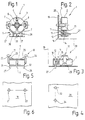
- a socket 1 which is used to connect tubular or rod-shaped fluorescent lamps.
- the socket 1 has a socket housing 2, on the front of which a rotatably mounted insert 3 is arranged.
- This insert which is approximately circular in its outer contour, has a slot 4 through which connecting pins of a fluorescent lamp (not shown further) can be inserted into the socket housing 2.
- the insert 3 is held by a pin 6 extending axially into the housing interior from a rear wall 5 of the socket housing 2, the slot 4 extending diametrically through the pin 6.
- resilient contacts 7, 8 are arranged, which serve as connection means for the fluorescent lamp and are visible in FIG. 1 through openings provided in the insert 3.
- the contacts extend into a line connection section 9 which is formed in one piece on the socket housing 2 and has two parallel grooves 11, 12 which are open towards the rear of the socket housing 2, as can be seen from FIG. 2.
- latching fingers 17, 18 extending parallel to one another at a distance from the rear of the socket housing 2 are formed, which can be brought into engagement with latching openings 21, 22 provided in a carrier 19.
- the locking fingers 17, 18 each extend for stiffening and better mounting over a side surface of the socket housing 2 and are otherwise designed so that they can spring to one another without damage.
- the latching fingers 17, 18 have contact surfaces 23, 24 aligned essentially parallel to the rear of the socket housing 2, which, when they are latched to the carrier 19 shown in FIG. 6, lie flat against the rear thereof.
- counterholders 25, 26 are also provided, which extend from the rear of the socket housing 2 onto the carrier 19.
- the counterholders 25, 26 exceed the width of the locking fingers 23, 24 considerably in order to avoid wobbling or tipping of the holder 1 when it is attached to the carrier 19.
- connection area 9 of the socket housing 2 additional locking fingers 27, 28 are formed, which serve as holding means for fastening and mounting the socket 1 in a second position, also referred to as the wiring position, on a support 29.
- the carrier 29 is arranged at right angles to the carrier 19, which is only schematically indicated in FIG. 3.
- the latching fingers 27, 28 extend substantially at right angles to the connection side of the socket housing 2 and, in contrast to the latching fingers 27, 28, have inclined contact surfaces 31, 32.
- the inclined position of the contact surfaces 31, 32 with respect to the longitudinal extent of the respective latching fingers 27, 28 enables the socket housing 2 to be releasably latched to the carrier 29.
- latch openings 33, 34 are formed in the carrier 29, the diameter and spacing of which, to avoid confusion, deviate from the diameter and the spacing of the latch openings 21, 22 in the carrier 19 (FIG. 6).
- an abutment rib 35 is also formed, which extends in an arc directly over the connection area 9 immediately following the insert 3.
- the abutment rib 35 is bifurcated and has an extension 36 running directly at the insulation displacement contact 16.
- the contact rib 35 and the extension 36 are provided with a flat contact surface 37 for supporting the socket housing 2 on the support 29.
- sockets 1 When prefabricating a lamp, sockets 1, as shown in FIG. 3, are attached to a lamp element serving as a support 29. In this position, the insulation displacement contacts 15, 16 are easily accessible. A wiring head or finger of an automatic wiring system can now press lines, not shown, from above into the slots of the insulation displacement contacts 15, 16 and lay the lines accordingly. When the lines are pressed in, the abutment rib 35 and the extension 36 are supported with the contact surface 37 on the support 29 and form a fixed abutment which keeps the socket housing 2 free of wobbles.
- the lamp is now made ready for shipment, the sockets remaining in the position shown in FIG. 3. Only at the installation site is the holder 1 released, for example by hand, from the carrier 29, the latching fingers 27, 28 due to the inclined position of the contact surfaces 31, 32 slide out relatively easily from the locking openings 33, 34.
- the socket 1 is now pivoted by approximately 90 ° into the position shown in FIGS. 1 and 2, the pivot axis described being transverse to the longitudinal extension of the fluorescent tube to be assembled later.
- the pivot axis lies in the vicinity of the insulation displacement contacts 15, 16, so that no special loads occur on the lines already connected.
- the rotated socket 1 is latched to the carrier 19 by the latching fingers 23, 24 being pushed into the latching openings 21, 22 shown in FIG. 6.
- the carrier 19 can be both an element of the preassembled lamp and an element or a cover cap at the installation location, for example a piece of furniture. In the latter cases, the version 1 offers not only easy wiring, but also considerable volume savings and improved handling during transport.
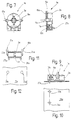
- FIGS. 7, 8, 9 and 11 A modified embodiment of the socket 1 is shown in FIGS. 7, 8, 9 and 11. Parts that are identical in construction and / or function to those in version 1 are provided with the same reference symbols, supplemented by the letter "a". In the version 1a, as shown in FIG. 8 in particular, there are no separate counterholders. Otherwise, versions 1 and 1a match.
- the wiring position shown in FIG. 9 coincides with the wiring position of the socket 1, and wiring and transport take place in the same way.
- the rear wall 5a lies flat against the carrier 19a.
- the carrier 19a thus covers the grooves 11a, 12a. Due to the large area of the Rear wall 5a on the carrier 19a is also obtained a rigid attachment of the socket 1a.
- the illustrated embodiment of the holder 1a can be modified by providing eyelets formed on the housing 2a instead of the latching fingers 17a, 18a, which are connected to the carrier 19a by means of screws, rivets or similar fastening means, the holder being otherwise unchanged.
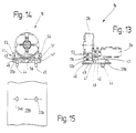
- FIGS. 13 and 14 A further modified embodiment is shown in FIGS. 13 and 14 as a version 1b.
- version 1b corresponds to the versions 1, 1a already described, the same reference numerals provided with a "b" for identification purposes are used. In this respect, the above description also applies to version 1b.
- the socket housing 2b is pivotally mounted on a base 42 via a hinge means 41.
- the one-piece base 42 has a section 43 lying flat on the support 29b, which is held on the support 29b with locking pins 44, 45. In their function, the locking pins 44, 45 correspond to the locking fingers 17, 18 in the exemplary embodiments described above.
- the extensions 46, 47 are designed as vertical wall sections, each of which has an opening 48 (only visible in FIG. 13 for the extension 46). These openings 48 serve to receive pins 49, 51, which are provided on the housing 2b and are aligned with one another and which together with the openings 48 define the hinge means 41.
- the extensions 46, 47 have sections that extend vertically upward as latching tongues 53, 54, which engage behind corresponding projections provided on the socket housing 2b when the socket housing 2b is in the position of use shown in solid lines in FIG. 13. In this position, the latching tongues 53, 54 also overlap the grooves 11b, 12b, which serve to receive connecting lines, and thus secure lines located in the grooves 11b, 12b.
- the base 42 has an abutment surface 56 formed by two mutually parallel ribs, on which the abutment rib 35b in the wiring position of the socket housing 2b shown in phantom in FIG. 13 lies on.
- the fastening means for holding the socket 1b in the position of use is formed by a cooperation of the locking pins 44, 45, the hinge means 41 and the locking tongues 53, 54.
- the holding means for holding the socket in the wiring position is formed by the cooperation of the locking pins 44, 45 of the base, the hinge means 41 and the contact surface 56 on the section 43 of the base 42. The wiring position is maintained during packaging and shipping. Only when the luminaire is installed is the lampholder housing 2b erected and thus transferred to the use position.
- a socket provided for use in an automatic wiring system in particular for fluorescent lamps, can be installed in two different positions, for which purpose it has corresponding fastening means and additional holding means.
- a first position defined by the holding means serves to fix the socket in a wiring position, while the other fastening means are used for Keep the socket in the use position.
- the position of use and wiring preferably differ by a rotation of 90 ° around a transverse axis.
- such a socket enables space-saving transport, in which the socket is protected and accommodated on a carrier in a space-saving manner.
Abstract
Description
Gegenstand der Erfindung ist eine Fassung zum Anschluß elektrischer Betriebsmittel mit den Merkmalen des Oberbegriffs des Patentanspruches 1.The invention relates to a socket for connecting electrical equipment with the features of the preamble of
Der Einsatz automatischer Verdrahtungssysteme zur automatischen Vorverdrahtung von anschlußfertigen Leuchteneinheiten erfordert, daß anzuschließende Kontakte für einen an der Verdrahtungseinrichtung vorgesehenen Verlegefinger oder -kopf zugänglich sind. Von seiten der Möbelhersteller, Designer oder anderer, mit dem Leuchtenentwurf befaßter Personenkreise kommt darüber hinaus die Forderung nach einer Verkleinerung von Lampen, Leuchten und deren Bestandteilen. Insbesondere Fassungen für Leuchtstofflampen sind, soweit sie in einen für die automatische Verdrahtungstechnik zugänglichen Anschlußbereich und in einen Anschlußbereich für die Leuchtstofflampe unterteilt sind, relativ voluminös. Sie schränken deshalb die Entwurfsfreiheit ein.The use of automatic wiring systems for the automatic pre-wiring of ready-to-connect lighting units requires that the contacts to be connected are accessible to a laying finger or head provided on the wiring device. On the part of furniture manufacturers, designers or other people involved in the design of luminaires, there is also a demand for the downsizing of lamps, luminaires and their components. In particular, sockets for fluorescent lamps are relatively voluminous insofar as they are divided into a connection area that is accessible for automatic wiring technology and a connection area for the fluorescent lamp. They therefore restrict freedom of design.
Leuchten für Leuchtstofflampen werden als vorverdrahtete und vorgefertigte Einheiten vom Hersteller meist ohne Leuchtstofflampen an den jeweiligen Abnehmer ausgeliefert. Die zur Aufnahme der Leuchtstofflampe vorgesehenen Fassungen beanspruchen bei der Verpackung und beim Transport jedoch dennoch den ansonsten von der Leuchtstofflampe in Anspruch genommenen Raum.Luminaires for fluorescent lamps are usually delivered to the respective customer as pre-wired and prefabricated units without fluorescent lamps. However, the sockets provided to accommodate the fluorescent lamp nevertheless take up the space otherwise occupied by the fluorescent lamp during packaging and transport.
Aus der mit der automatischen Verdrahtungstechnik zusammenhängenden Problematik heraus ist für Leuchten mit Einbaugehäuse die aus dem DE 295 05 451 U1 hervorgehende Lampenfassung vorgeschlagen worden. Die genannten Anbaugehäuse sind bei den Enden einer Leuchtstofflampe vorgesehene, einseitig offene Gehäuse, die an der Leuchte fest gehalten sind und das jeweilige Ende der Leuchtstofflampe aufnehmen. Eine Fassung zur Halterung und zum elektrischen Anschluß der Leuchtstofflampe ist in dem Anbaugehäuse angeordnet. Die Anbaugehäuse dienen dabei dazu, die sichtbare Länge der Leuchtstofflampe auf ein bei Deckenvertäfelungen übliches Raster zu begrenzen und die insbesondere durch die Fassungen entstehenden Überlängen hinter der genannten Deckenverkleidung verschwinden zu lassen. Um die Fassungen automatisch verdrahten zu können, ist die die Fassung tragende Rückwand längsverschiebbar in dem Gehäuse gehalten. Die Rückwand kann dabei so weit auf die lampenseitige Öffnung des Anbaugehäuses zu verschoben werden, daß die Fassung von der Seite her zugänglich ist. Dort befinden sich Leitereinstecköffnungen zum Anschluß von Leitungen.Out of the problem associated with the automatic wiring technology, the lamp holder which is disclosed in DE 295 05 451 U1 has been proposed for luminaires with a built-in housing. Said attachment housings are housings which are provided at the ends of a fluorescent lamp and are open on one side and are held firmly on the lamp and accommodate the respective end of the fluorescent lamp. A socket for the holder and for the electrical connection of the fluorescent lamp is arranged in the attachment housing. The add-on housings serve to limit the visible length of the fluorescent lamp to a grid that is customary in the case of ceiling paneling and to make the excess lengths that arise in particular from the sockets disappear behind the ceiling cladding mentioned. In order to be able to wire the sockets automatically, the rear wall carrying the socket is held in the housing in a longitudinally displaceable manner. The rear wall can be moved so far towards the lamp-side opening of the attachment housing that the socket is accessible from the side. There are conductor insertion openings for connecting cables.
Der Platzbedarf einer solchen Fassung wird durch das Volumen des Anbaugehäuses bestimmt.The space requirement of such a socket is determined by the volume of the attachment housing.
Dagegen ist es Aufgabe der Erfindung, eine Fassung zu schaffen, die auch bei beengten Platzverhältnissen automatisch verdrahtet werden kann, so daß eine Vorverdrahtung und dennoch ein platzsparender Transport möglich ist.In contrast, it is an object of the invention to provide a socket that can be automatically wired even in confined spaces, so that pre-wiring and yet a space-saving transport is possible.
Diese Aufgabe wird durch eine Fassung mit den Merkmalen des Patentanspruches 1 gelöst.This object is achieved by a version with the features of
Das insbesondere für die Schneidklemmtechnik geeignete Fassungsgehäuse kann in unterschiedlichen Positionen an einem Leuchtenelement befestigt werden. Die erste, als Gebrauchsposition bezeichnete Position dient der betriebsmäßigen Halterung und Stromversorgung bspw. einer Leuchtstofflampe. Das zusätzlich vorgesehene Halterungsmittel ermöglicht es, die Fassung in einer davon verschiedenen Position mit dem Leuchtenelement oder einem anderweitigen Träger zu verbinden. Diese Position dient dem automatischen Einführen und Anschließen von Leitungen, bspw. bei der Vorverdrahtung einer Leuchte. Diese Position kann zugleich als Transportposition verwendet werden, in der die Fassung bspw. flach auf einem Träger liegt. In dieser Liegeposition ist die Fassung auch bei ansonsten beengten Platzverhältnissen gut zugänglich. Darüber hinaus ist sie im Hinblick auf die Verpackung und den Transport der vormontierten Leuchte platzsparend untergebracht. Die Fassung ist in dieser Position, in der sie nicht von einem Leuchtenkörper wegsteht sondern vorzugsweise flach auf diesem liegt, vor Beschädigung geschützt.The socket housing, which is particularly suitable for insulation displacement technology, can be attached to a lamp element in different positions. The first position, referred to as the use position, is used for operational mounting and power supply, for example of a fluorescent lamp. The additionally provided holding means makes it possible to connect the socket to the lamp element or another support in a different position. This position is used for the automatic insertion and connection of cables, for example when prewiring a luminaire. This position can also be used as a transport position in which the holder lies flat on a carrier, for example. In this lying position, the socket is easily accessible even in otherwise confined spaces. In addition, it is housed in a space-saving manner with regard to the packaging and transport of the preassembled luminaire. The socket is protected from damage in this position, in which it does not protrude from a lamp body but preferably lies flat on it.
Gute Zugänglichkeit bei der Verdrahtung und ein mechanischer und elektrischer Schutz der Anschlüsse wird überdies erhalten, wenn bspw. als Schneidklemmkontakte ausgebildete Leitungsanschlußmittel von einer Gehäuseseite (Rückseite) her zugänglich sind, die von der Gehäuseseite (Vorderseite) abgewandt ist, von der die in dem Fassungsgehäuse berührungssicher gehaltenen elektrischen Kontaktmittel her zugänglich sind. Die Leitungsanschlußmittel liegen dann in von der Anschlußseite her wegweisenden Öffnungen. Im Falle von Fassungen für Leuchtstofflampen sind diese Öffnungen ohnehin durch weitere Elemente der Leuchte oder durch Abdeckelemente, Kappen oder dergleichen, abgedeckt.Good accessibility in the wiring and mechanical and electrical protection of the connections is moreover obtained if, for example, line connection means designed as insulation displacement contacts are accessible from a housing side (rear side) that faces away from the housing side (front side), from which the in the socket housing accessible electrical contact means are accessible. The line connection means are then pointing away from the connection side Openings. In the case of sockets for fluorescent lamps, these openings are covered anyway by further elements of the lamp or by cover elements, caps or the like.
Eine besonders platzsparende Position zur Verdrahtung und zum Transport ergibt sich, wenn sich die Gebrauchsposition von der zweiten Position um eine Drehung von vorzugsweise 90° unterscheidet. Dabei ist es vorteilhaft, wenn die Dreh- oder Schwenkachse für diese Bewegung quer zu der Längsachse einer bspw. anzuschließenden Leuchtstofflampe ausgerichtet ist sowie im Abstand zu dieser verläuft.A particularly space-saving position for wiring and transport results if the use position differs from the second position by a rotation of preferably 90 °. It is advantageous if the rotation or swivel axis for this movement is aligned transversely to the longitudinal axis of a fluorescent lamp to be connected, for example, and is at a distance from it.
Bei einer zu bevorzugenden Lösung sind die Gebrauchsposition und die zweite, auch als Verdrahtungs- und/oder Transportposition bezeichnete, Position so festgelegt, daß die an die Fassung angeschlossenen Leitungen beim Überführen der Fassung in ihre Gebrauchsposition weder gezogen noch gestaucht werden. Dies kann bspw. dadurch erreicht werden, daß die Leitungen im Bereich der zum Verschwenken der Fassung vorgesehenen Schwenkachse zu der Fassung führen. Dies ist unabhängig davon, ob die Fassung mittels eines Scharnieres geführt oder scharnierlos ausgebildet ist. Ein an der Fassung vorgesehenes Anschlagmittel, das vorzugsweise im Bereich der als Leitungsanschlußmittel dienenden Schneidklemmkontakte angeordnet ist, dient als Widerlager zur Ableitung der beim Verdrahten in Schneidklemmtechnik auftretenden Kräfte. Das Widerlager ist vorzugsweise eine mit einer geeigneten Unterlage in Berührung stehende Anlagerippe mit einer bogenförmigen ebenen Anlagefläche. Eine solche Rippe steift das Gehäuse aus und überträgt die Kräfte in dem erforderlichen Maße. Zur Unterstützung kann die Rippe eine Verzweigung oder Gabelung aufweisen.In a preferred solution, the position of use and the second position, also referred to as the wiring and / or transport position, are defined in such a way that the lines connected to the socket are neither pulled nor compressed when the socket is transferred into its position of use. This can be achieved, for example, by the lines leading to the mount in the region of the pivot axis provided for pivoting the mount. This is irrespective of whether the frame is guided by means of a hinge or is designed without a hinge. A stop means provided on the socket, which is preferably arranged in the area of the insulation displacement contacts serving as line connection means, serves as an abutment for deriving the forces that occur during wiring in insulation displacement technology. The abutment is preferably an abutment rib in contact with a suitable base with an arcuate flat abutment surface. Such a rib stiffens the housing and transmits the forces to the required extent. The rib may have a branch or bifurcation for support.
Bei einer besonders einfach zu handhabenden Variante der Fassung ist das Fassungsgehäuse auf einem Sockel schwenkbar gelagert. Dazu dient ein Scharnier, das in Verbindung mit einem zwischen Sockel und Fassungsgehäuse wirksamen Anschlagmittel das Halterungsmittel zum Halten der Fassung in der zweiten Position (Verdrahtungsposition) bildet. Zur Arretierung in der Gebrauchsposition sind an dem Sockel vorzugsweise Rastmittel vorgesehen, die mit dem Fassungsgehäuse zusammenwirken und dieses in Gebrauchsposition arretieren, sobald das Fassungsgehäuse in diese geschwenkt ist. Die bspw. als Rastnasen ausgebildeten Rastmittel, die an dem Sockel vorgesehen sind, können dabei zusätzlich zur Sicherung der angeschlossenen Leitungen in ihrer kontaktierten Lage dienen.In a particularly easy-to-use variant of the socket, the socket housing is pivotally mounted on a base. For this purpose, a hinge is used which, in conjunction with a stop means effective between the base and the socket housing, forms the holding means for holding the socket in the second position (wiring position). For locking in the use position, locking means are preferably provided on the base, which cooperate with the socket housing and lock it in the position of use as soon as the socket housing is pivoted into it. The latching means, which are designed, for example, as latching lugs and are provided on the base, can additionally serve to secure the connected lines in their contacted position.
Bedarfsweise kann der Sockel auch als Bestandteil oder Abschnitt eines Leuchtenelementes ausgebildet sein. Dies reduziert die Anzahl der für eine Leuchte erforderlichen Bauelemente.If necessary, the base can also be designed as a component or section of a lighting element. This reduces the number of components required for a luminaire.
Während das Fassungsgehäuse wegen der Eigenerwärmung von Leuchtstofflampen eine relativ hohe Wärmebeständigkeit aufweisen muß, kann als Sockel ein kostengünstigeres Material mit niedrigerer Wärmebeständigkeit verwendet werden. Damit läßt sich insgesamt der Aufwand von wärmebeständigem Kunststoff pro Fassung reduzieren.While the socket housing must have a relatively high heat resistance due to the self-heating of fluorescent lamps, a lower-cost material with lower heat resistance can be used as the base. This can reduce the overall cost of heat-resistant plastic per socket.
Die Fassung ist vorzugsweise so ausgebildet, daß daran vorhandene strom- oder spannungsführende Teile berührungssicher gehalten sind. Dies erübrigt gegebenenfalls weitere Abdeckmaßnahmen.The socket is preferably designed in such a way that current or voltage-carrying parts present on it are held securely against contact. This may make further masking measures unnecessary.
In der Zeichnung sind Ausführungsbeispiele der Erfindung dargestellt. Es zeigen:
- Fig. 1
- eine in Gebrauchsposition sowie in einer zweiten Position mit einem Leuchtenelement verbindbare Fassung für Leuchtstofflampen, in einer Vorderansicht mit Blickrichtung auf ihre Seite zum Anschluß der Lampen, in schematisierter Darstellung,
- Fig. 2
- die Fassung nach Fig. 1, die auf einem Träger in Gebrauchsposition befestigt ist, in einer schematisierten Seitenansicht,
- Fig. 3
- die Fassung nach den Fig. 1 und 2, die auf einem Träger in Verdrahtungsposition befestigt ist, in schematisierter Seitenansicht,
- Fig. 4
- den die Fassung nach Fig. 3 in Verdrahtungsposition haltenden Träger in Draufsicht,
- Fig. 5
- die Fassung nach Fig. 1 in Draufsicht,
- Fig. 6
- den die Fassung nach Fig. 2 in Gebrauchsposition haltenden Träger in Draufsicht,
- Fig. 7 u. Fig. 8
- eine abgewandelte Ausführungsform der Fassung, in Gebrauchsposition, in Vorder- und Seitenansicht,
- Fig. 9
- die Fassung nach den Fig. 7 und 8 in Verdrahtungsposition, montiert auf einen Träger, in Seitenansicht,
- Fig. 10
- den Träger nach Fig. 9 in Draufsicht,
- Fig. 11
- die Fassung nach Fig. 7 in Draufsicht,
- Fig. 12
- einen Träger zur Halterung der Fassung nach Fig. 8 in Gebrauchsposition, in einer ausschnittsweisen Draufsicht,
- Fig. 13
- eine abgewandelte Ausführungsform der Fassung mit einem mittels eines Scharnieres von einem Sockel getragenen Fassungsgehäuse, montiert auf einen Träger, in Seitenansicht und in schematisierter Darstellung,
- Fig. 14
- die Fassung nach Fig. 13 in Gebrauchsposition und in einer schematisierten Vorderansicht und
- Fig. 15
- den Träger nach Fig. 13 in einer ausschnittsweisen Draufsicht.
- Fig. 1
- a socket for fluorescent lamps which can be connected in the use position and in a second position with a lamp element, in a front view looking towards its side for connecting the lamps, in a schematic representation,
- Fig. 2
- 1, which is attached to a carrier in the use position, in a schematic side view,
- Fig. 3
- 1 and 2, which is attached to a carrier in the wiring position, in a schematic side view,
- Fig. 4
- 3 in top view holding the holder in the wiring position,
- Fig. 5
- 1 in top view,
- Fig. 6
- the support holding the socket of FIG. 2 in the use position in plan view,
- Fig. 7 u. Fig. 8
- a modified embodiment of the socket, in the use position, in front and side view,
- Fig. 9
- 7 and 8 in the wiring position, mounted on a carrier, in side view,
- Fig. 10
- 9 in top view,
- Fig. 11
- 7 in top view,
- Fig. 12
- 8 in the use position, in a partial plan view,
- Fig. 13
- 1 shows a modified embodiment of the holder with a holder housing carried by a hinge from a base, mounted on a carrier, in a side view and in a schematic representation,
- Fig. 14
- 13 in the use position and in a schematic front view and
- Fig. 15
- the carrier of FIG. 13 in a partial plan view.
In den Fig. 1 und 2 ist eine Fassung 1 dargestellt, die dem Anschluß von rohr- oder stabförmigen Leuchtstofflampen dient. Die Fassung 1 weist ein Fassungsgehäuse 2 auf, an dessen Vorderseite ein drehbar gelagerter Einsatz 3 angeordnet ist. Dieser in seiner Außenkontur etwa kreisförmige Einsatz weist einen Schlitz 4 auf, durch den Anschlußstifte einer nicht weiter dargestellten Leuchtstofflampe in das Fassungsgehäuse 2 eingeführt werden können. Der Einsatz 3 ist von einem sich von einer Rückwand 5 des Fassungsgehäuses 2 axial in das Gehäuseinnere hinein erstreckenden Zapfen 6 gehalten, wobei sich der Schlitz 4 diametral durch den Zapfen 6 erstreckt.1 and 2, a
In einem von dem Fassungsgehäuse 2 umschlossenen Innenraum sind federnd ausgebildete Kontakte 7, 8 angeordnet, die als Anschlußmittel für die Leuchtstofflampe dienen und in Fig. 1 durch in dem Einsatz 3 vorgesehene Öffnungen hindurch sichtbar sind. Die Kontakte erstrecken sich bis in einen einstückig an dem Fassungsgehäuse 2 ausgebildeten Leitungsanschlußabschnitt 9, der zwei parallele, zur Rückseite des Fassungsgehäuses 2 hin offene Nuten 11, 12 aufweist, wie aus Fig. 2 hervorgeht.In an interior space enclosed by the
Seitlich gegeneinander versetzt, d.h. in Fig. 2 rechts unten links, sind innerhalb der Nuten 11, 12 jeweils zwei parallele geschlitzte Querwände vorgesehen, die jeweils ein zueinander paralleles Wandpaar 13, 14 bilden. Zwischen den Wänden des in der Nut 11 sitzenden Wandpaares 13 ist ein endseitig an dem Kontakt 8 ausgebildeter Schneidklemmkontakt 15 berührungssicher gehalten. Entsprechend ist ein an dem Kontakt 7 endseitig ausgebildeter Schneidklemmkontakt 16 zwischen den Wänden des in der Nut 12 sitzenden Wandpaares 14 gehalten.Staggered laterally, i.e. In Fig. 2 bottom right, two parallel slotted transverse walls are provided within the
Zur Halterung der Fassung 1 in der dargestellten Verdrahtungsposition sind an dem Fassungsgehäuse 2, wie insbesondere aus Fig. 5 hervorgeht, zwei, sich im Abstand parallel zueinander von der Rückseite des Fassungsgehäuses 2 weg erstreckende, Rastfinger 17, 18 ausgebildet, die mit in einem Träger 19 vorgesehenen Rastöffnungen 21, 22 in Eingriff bringbar sind. Die Rastfinger 17, 18 erstrecken sich dabei zur Aussteifung und besseren Halterung jeweils über eine Seitenfläche des Fassungsgehäuses 2 und sind im übrigen so ausgebildet, daß sie ohne Beschädigung aufeinander zu federn können. Die Rastfinger 17, 18 weisen im wesentlichen parallel zu der Rückseite des Fassungsgehäuses 2 ausgerichtete Anlageflächen 23, 24 auf, die, wenn sie mit dem in Fig. 6 dargestellten Träger 19 verrastet sind, flach an dessen Rückseite anliegen. Zur spielfreien Arretierung des Fassungsgehäuses 2 auf dem Träger 19 sind außerdem Gegenhalter 25, 26 vorgesehen, die sich von der Rückseite des Fassungsgehäuses 2 auf den Träger 19 zu erstrecken. Die Gegenhalter 25, 26 übersteigen in ihrer Breite die Breite der Rastfinger 23, 24 erheblich, um ein Wackeln oder Kippen der Fassung 1 zu vermeiden, wenn diese an dem Träger 19 befestigt ist.To hold the
In dem Anschlußbereich 9 des Fassungsgehäuses 2 sind zusätzliche Rastfinger 27, 28 ausgebildet, die als Halterungsmittel zur Befestigung und Lagerung der Fassung 1 in einer zweiten, auch als Verdrahtungsposition bezeichneten, Position auf einem Träger 29 dienen. Der Träger 29 ist zu dem in Fig. 3 lediglich schematisch angedeuteten Träger 19 im rechten Winkel angeordnet.In the
Die Rastfinger 27, 28 erstrecken sich im wesentlichen rechtwinklig zu der Anschlußseite des Fassungsgehäuses 2 und weisen im Gegensatz zu den Rastfingern 27, 28 schrägstehende Anlageflächen 31, 32 auf. Die Schrägstellung der Anlageflächen 31, 32 in Bezug auf die Längserstreckung des jeweiligen Rastfingers 27, 28 ermöglicht ein lösbares Verrasten des Fassungsgehäuses 2 mit dem Träger 29.The latching
Zur Aufnahme der federnd ausgebildeten Rastfinger 27, 28 sind in dem Träger 29 Rastöffnungen 33, 34 ausgebildet, deren Durchmesser und Abstand zur Vermeidung von Verwechslungen von dem Durchmesser und dem Abstand der Rastöffnungen 21, 22 in dem Träger 19 (Fig. 6) abweicht.To accommodate the resilient latching
In dem Anschlußbereich 9 des Fassungsgehäuses 2 ist außerdem eine Anlagerippe 35 ausgebildet, die sich unmittelbar im Anschluß an den Einsatz 3 bogenförmig über den Anschlußbereich 9 erstreckt. Die Anlagerippe 35 ist gegabelt und weist einen unmittelbar bei dem Schneidklemmkontakt 16 verlaufenden Fortsatz 36 auf. Die Anlagerippe 35 und der Fortsatz 36 sind mit einer planen Anlagefläche 37 zum Abstützen des Fassungsgehäuses 2 an dem Träger 29 versehen.In the
Die insoweit beschriebene Fassung 1 wird folgendermaßen verwendet:
Bei der Vorfertigung einer Leuchte werden Fassungen 1, wie in Fig. 3 dargestellt, auf einem als Träger 29 dienenden Leuchtenelement befestigt. In dieser Lage sind die Schneidklemmkontakte 15, 16 gut zugänglich. Ein Verdrahtungskopf oder -finger eines automatischen Verdrahtungssystemes kann nun nicht weiter dargestellte Leitungen von oben her in die Schlitze der Schneidklemmkontakte 15, 16 einpressen und die Leitungen entsprechend verlegen. Beim Eindrücken der Leitungen stützen sich die Anlagerippe 35 und der Fortsatz 36 mit der Anlagefläche 37 auf dem Träger 29 ab und bilden ein festes Widerlager, das das Fassungsgehäuse 2 wackelfrei hält.When prefabricating a lamp,
Die Leuchte wird nun versandfertig gemacht, wobei die Fassungen in der in Fig. 3 dargestellten Position verbleiben. Erst am Einbauort wird die Fassung 1 bspw. von Hand von dem Träger 29 gelöst, wobei die Rastfinger 27, 28 aufgrund der Schrägstellung der Anlageflächen 31, 32 relativ leicht aus den Rastöffnungen 33, 34 herausgleiten. Die Fassung 1 wird nun um etwa 90° in die in den Fig. 1 und 2 dargestellte Lage verschwenkt, wobei die dabei beschriebene Schwenkachse quer zur Längserstreckung der später zu montierenden Leuchtstoffröhre liegt. Die Schwenkachse liegt dabei in der Nähe der Schneidklemmkontakte 15, 16, so daß hier keine besonderen Belastungen an den bereits angeschlossenen Leitungen auftreten.The lamp is now made ready for shipment, the sockets remaining in the position shown in FIG. 3. Only at the installation site is the
Die gedrehte Fassung 1 wird mit dem Träger 19 verrastet, indem die Rastfinger 23, 24 in die, aus Fig. 6 hervorgehenden, Rastöffnungen 21, 22 eingeschoben werden. In dieser Lage sind die ohnehin berührungssicher in dem Fassungsgehäuse 2 gehaltenen Schneidklemmkontakte 15, 16 dem Träger 19 zugewandt und somit nochmals abgedeckt. Der Träger 19 kann dabei sowohl ein Element der vormontierten Leuchte als auch ein am Einbauort, bspw. einem Möbelstück, vorhandenes Element oder eine Abdeckkappe sein. In den letztgenannten Fällen bietet die Fassung 1 neben der leichten Verdrahtbarkeit eine erhebliche Volumeneinsparung und verbesserte Handhabung beim Transport.The rotated
Eine abgewandelte Ausführungsform der Fassung 1 ist in den Fig. 7, 8, 9 und 11 dargestellt. Teile, die mit denen der Fassung 1 bau- und/oder funktionsgleich sind, sind mit gleichen Bezugszeichen, ergänzt durch den Buchstaben "a", versehen. Bei der Fassung 1a fehlen, wie insbesondere aus Fig. 8 hervorgeht, gesonderte Gegenhalter. Ansonsten stimmen die Fassungen 1 und 1a überein. Die in Fig. 9 dargestellte Verdrahtungsstellung stimmt mit der Verdrahtungsstellung der Fassung 1 überein und Verdrahtung und Transport laufen auf gleiche Weise ab.A modified embodiment of the
In Gebrauchsstellung liegt jedoch die Rückwand 5a flach an dem Träger 19a an. Der Träger 19a deckt damit die Nuten 11a, 12a ab. Durch die großflächige Anlage der Rückwand 5a an dem Träger 19a wird überdies eine steife Befestigung der Fassung 1a erhalten.In the position of use, however, the
Die dargestellte Ausführungsform der Fassung 1a kann abgewandelt werden, indem anstelle der Rastfinger 17a, 18a an dem Gehäuse 2a angeformte Ösen vorgesehen werden, die mittels Schrauben, Nieten oder dergleichen Befestigungsmittel mit dem Träger 19a verbunden werden, wobei die Fassung ansonsten unverändert ist.The illustrated embodiment of the
Eine darüber hinaus abgewandelte Ausführungsform ist in den Fig. 13 und 14 als Fassung 1b dargestellt. Soweit die Fassung 1b mit den bereits beschriebenen Fassungen 1, 1a übereinstimmt, werden gleiche, zur Kenntlichmachung mit einem "b" versehene Bezugszeichen verwendet. Die vorstehende Beschreibung gilt insoweit auch für die Fassung 1b.A further modified embodiment is shown in FIGS. 13 and 14 as a
Das Fassungsgehäuse 2b ist über ein Scharniermittel 41 an einem Sockel 42 schwenkbar gelagert. Der einstückig ausgebildete Sockel 42 weist einen flach auf dem Träger 29b liegenden Abschnitt 43 auf, der mit Rastzapfen 44, 45 an dem Träger 29b gehalten ist. In ihrer Funktion entsprechen die Rastzapfen 44, 45 den Rastfingern 17, 18 bei den vorstehend beschriebenen Ausführungsbeispielen. Von dem Abschnitt 43 erstrecken sich zwei im Abstand parallel zueinander gehaltene Fortsätze 46, 47 in Richtung von den Rastzapfen 44, 45 weg. Die Fortsätze 46, 47 sind als vertikale Wandabschnitte ausgebildet, die jeweils eine Öffnung 48 (sichtbar lediglich in Fig. 13 für den Fortsatz 46) vorgesehen sind. Diese Öffnungen 48 dienen der Aufnahme von an dem Gehäuse 2b vorgesehenen, miteinander fluchtenden Zapfen 49, 51, die gemeinsam mit den Öffnungen 48 das Scharniermittel 41 definieren.The
Endseitig sind die Fortsätze 46, 47 mit sich vertikal nach oben erstreckenden Abschnitten als Rastzungen 53, 54 ausgebildet, die entsprechende, an dem Fassungsgehäuse 2b vorgesehene Vorsprünge hintergreifen, wenn das Fassungsgehäuse 2b in der in Fig. 13 mit durchgezogenen Linien dargestellten Gebrauchsstellung befindlich ist. In dieser Stellung überschneiden die Rastzungen 53, 54 auch die Nuten 11b, 12b, die der Aufnahme von Anschlußleitungen dienen, und sichern damit in den Nuten 11b, 12b befindliche Leitungen.At the end, the
Um bei der Verdrahtung eine feste Anlage für das Fassungsgehäuse 2b an dem Sockel 42 zu schaffen, weist der Sockel 42 eine von zwei zueinander parallelen Rippen gebildete Anlagefläche 56 auf, auf der die Anlagerippe 35b in der in Fig. 13 strichpunktiert dargestellten Verdrahtungsposition des Fassungsgehäuses 2b aufliegt.In order to create a firm contact for the
Bei dieser Ausführungsform wird das Befestigungsmittel zur Halterung der Fassung 1b in Gebrauchsposition durch ein Zusammenwirken der Rastzapfen 44, 45, des Scharniermittels 41 und der Rastzungen 53, 54 gebildet. Das Halterungsmittel zur Halterung der Fassung in Verdrahtungsposition wird durch Zusammenwirken der Rastzapfen 44, 45 des Sockels, des Scharniermittels 41 und der Anlagefläche 56 an dem Abschnitt 43 des Sockels 42 gebildet. Die Verdrahtungsposition wird beim Verpacken und beim Versand beibehalten. Erst bei der Installation der Leuchte wird das Fassungsgehäuse 2b aufgerichtet und somit in Gebrauchsstellung überführt.In this embodiment, the fastening means for holding the
Eine für den Einsatz bei einem automatischen Verdrahtungssystem vorgesehene Fassung, insbesondere für Leuchtstofflampen, kann in zwei voneinander unterschiedlichen Positionen montiert werden, wozu sie entsprechende Befestigungsmittel und zusätzliche Halterungsmittel aufweist. Eine erste von dem Halterungsmittel definierte Lage dient der Festlegung der Fassung in einer Verdrahtungsposition, während die übrigen Befestigungsmittel zum Halten der Fassung in Gebrauchsposition dienen. Gebrauchs- und Verdrahtungsposition unterscheiden sich vorzugsweise durch eine Drehung um 90° um eine Querachse. Eine derartige Fassung ermöglicht neben der automatischen Verdrahtung einen platzsparenden Transport, bei dem die Fassung geschützt und platzsparend an einem Träger untergebracht ist.A socket provided for use in an automatic wiring system, in particular for fluorescent lamps, can be installed in two different positions, for which purpose it has corresponding fastening means and additional holding means. A first position defined by the holding means serves to fix the socket in a wiring position, while the other fastening means are used for Keep the socket in the use position. The position of use and wiring preferably differ by a rotation of 90 ° around a transverse axis. In addition to the automatic wiring, such a socket enables space-saving transport, in which the socket is protected and accommodated on a carrier in a space-saving manner.
Claims (16)
mit einem Fassungsgehäuse, das zur mechanischen Halterung und zur elektrischen Kontaktierung des Betriebsmittels eingerichtet ist, und
mit einem Befestigungsmittel zur Halterung der Fassung in einer Gebrauchsposition, in der das Betriebsmittel gehalten und kontaktiert ist,
dadurch gekennzeichnet,
daß die Fassung (1) außerdem ein Halterungsmittel (27, 28) zur Halterung der Fassung (1) in einer in von der Gebrauchsposition verschiedenen zweiten Position zur Verdrahtung und zum raumsparenden Transport aufweist.Socket for connecting electrical equipment, especially fluorescent lamps,
with a socket housing that is set up for mechanical mounting and electrical contacting of the equipment, and
with a fastening means for holding the socket in a position of use in which the equipment is held and contacted,
characterized,
that the socket (1) also has a holding means (27, 28) for holding the socket (1) in a different position from the position of use for wiring and space-saving transport.
Applications Claiming Priority (2)
| Application Number | Priority Date | Filing Date | Title |
|---|---|---|---|
| DE19603375A DE19603375C2 (en) | 1996-01-31 | 1996-01-31 | Space-saving frame |
| DE19603375 | 1996-01-31 |
Publications (2)
| Publication Number | Publication Date |
|---|---|
| EP0787944A1 true EP0787944A1 (en) | 1997-08-06 |
| EP0787944B1 EP0787944B1 (en) | 2003-03-05 |
Family
ID=7784100
Family Applications (1)
| Application Number | Title | Priority Date | Filing Date |
|---|---|---|---|
| EP97100720A Expired - Lifetime EP0787944B1 (en) | 1996-01-31 | 1997-01-17 | Compact lamp holder |
Country Status (4)
| Country | Link |
|---|---|
| EP (1) | EP0787944B1 (en) |
| AT (1) | ATE233880T1 (en) |
| DE (2) | DE19603375C2 (en) |
| ES (1) | ES2189894T3 (en) |
Cited By (1)
| Publication number | Priority date | Publication date | Assignee | Title |
|---|---|---|---|---|
| DE19819182A1 (en) * | 1998-04-29 | 1999-11-04 | Walter Holzer | Compact light that is safe to touch |
Families Citing this family (3)
| Publication number | Priority date | Publication date | Assignee | Title |
|---|---|---|---|---|
| DE19745762C1 (en) | 1997-10-16 | 1999-08-26 | Vossloh Schwabe Gmbh | Fluorescent lamp holder with improved pin support |
| CN101877296B (en) * | 2010-07-06 | 2012-09-05 | 浙江深度光电科技有限公司 | Automatic riveting device of energy-saving light |
| DE102019107785A1 (en) * | 2019-03-26 | 2020-10-01 | Alfred Pracht Lichttechnik Gmbh | lamp |
Citations (5)
| Publication number | Priority date | Publication date | Assignee | Title |
|---|---|---|---|---|
| GB607051A (en) * | 1946-01-24 | 1948-08-25 | F W Thorpe Ltd | Improvements in fittings for tubular electric discharge lamps |
| US3080476A (en) * | 1960-02-25 | 1963-03-05 | John C Virden Company | Fluorescent lighting fixture |
| DE3423357A1 (en) * | 1984-06-25 | 1986-01-02 | Licentia Patent-Verwaltungs-Gmbh, 6000 Frankfurt | Holder arrangement for fluorescent lamps |
| US5148086A (en) * | 1990-07-06 | 1992-09-15 | Valmont Industries, Inc. | Means for securing insulation displacement terminals to leads extending from a fluorescent light ballast |
| DE29505451U1 (en) | 1995-03-31 | 1995-06-01 | Broekelmann Jaeger & Busse | Attachment housing for a lamp holder in luminaire housings |
-
1996
- 1996-01-31 DE DE19603375A patent/DE19603375C2/en not_active Expired - Fee Related
-
1997
- 1997-01-17 EP EP97100720A patent/EP0787944B1/en not_active Expired - Lifetime
- 1997-01-17 DE DE59709417T patent/DE59709417D1/en not_active Expired - Lifetime
- 1997-01-17 AT AT97100720T patent/ATE233880T1/en active
- 1997-01-17 ES ES97100720T patent/ES2189894T3/en not_active Expired - Lifetime
Patent Citations (5)
| Publication number | Priority date | Publication date | Assignee | Title |
|---|---|---|---|---|
| GB607051A (en) * | 1946-01-24 | 1948-08-25 | F W Thorpe Ltd | Improvements in fittings for tubular electric discharge lamps |
| US3080476A (en) * | 1960-02-25 | 1963-03-05 | John C Virden Company | Fluorescent lighting fixture |
| DE3423357A1 (en) * | 1984-06-25 | 1986-01-02 | Licentia Patent-Verwaltungs-Gmbh, 6000 Frankfurt | Holder arrangement for fluorescent lamps |
| US5148086A (en) * | 1990-07-06 | 1992-09-15 | Valmont Industries, Inc. | Means for securing insulation displacement terminals to leads extending from a fluorescent light ballast |
| DE29505451U1 (en) | 1995-03-31 | 1995-06-01 | Broekelmann Jaeger & Busse | Attachment housing for a lamp holder in luminaire housings |
Cited By (1)
| Publication number | Priority date | Publication date | Assignee | Title |
|---|---|---|---|---|
| DE19819182A1 (en) * | 1998-04-29 | 1999-11-04 | Walter Holzer | Compact light that is safe to touch |
Also Published As
| Publication number | Publication date |
|---|---|
| DE59709417D1 (en) | 2003-04-10 |
| ATE233880T1 (en) | 2003-03-15 |
| EP0787944B1 (en) | 2003-03-05 |
| DE19603375A1 (en) | 1997-08-07 |
| ES2189894T3 (en) | 2003-07-16 |
| DE19603375C2 (en) | 1997-12-04 |
Similar Documents
| Publication | Publication Date | Title |
|---|---|---|
| EP2650594B1 (en) | Light with lamp | |
| DE102019000410B4 (en) | Lamp and adapter for lamp | |
| DE4432509A1 (en) | Electrical installation device, especially for cable ducts | |
| EP0012234B1 (en) | Fluorescent lighting fixture | |
| EP0787944B1 (en) | Compact lamp holder | |
| EP1150399B1 (en) | Multipolar electrical connector | |
| EP1460734A2 (en) | Conductor rail adapter | |
| EP2650595B1 (en) | Light strip with luminaire | |
| EP0825688B1 (en) | Electronic ballast for rail mounted lamps | |
| EP0788188B1 (en) | Insulation displacement socket | |
| EP0833547B1 (en) | Light signalling device | |
| EP0802586A2 (en) | Sockel, especially for rod-shaped fluorescent tubes | |
| EP0392198B1 (en) | Elongated light fixture | |
| DE19615372C2 (en) | Mounting box with a lamp holder for two-pin fluorescent lamps or the like | |
| DE10158633A1 (en) | Fixing device for light sources in vehicle lights has holder body that can be inserted into lamp bearer with electrical conductors to supply, adapter for cable group or reflector holder | |
| DE3226394C2 (en) | ||
| EP1351347A1 (en) | Socket for electrical installation | |
| DE102012107907A1 (en) | Lamp module for fluorescent lamp, has socket or cover portion with fastening unit, by which socket and cover portion are detachably mounted on base rail, where socket has two dividing contacts that penetrate socket attached to base rail | |
| EP0825381B1 (en) | Housing for lamp socket in light fixture housings | |
| EP0735314B1 (en) | Housing for a lamp socket to be mounted on the light fixture housing | |
| DE69837191T2 (en) | lamp | |
| EP0901203B1 (en) | Resiliently mounted lamp socket | |
| DE202022103438U1 (en) | Electrical module for connecting to a mounting rail and contacting element for this | |
| DE3129707A1 (en) | LAMP FOR A LOW-PRESSURE GAS DISCHARGE LAMP | |
| EP1248037B1 (en) | Mounting device |
Legal Events
| Date | Code | Title | Description |
|---|---|---|---|
| PUAI | Public reference made under article 153(3) epc to a published international application that has entered the european phase |
Free format text: ORIGINAL CODE: 0009012 |
|
| AK | Designated contracting states |
Kind code of ref document: A1 Designated state(s): AT BE DE ES FR GB IT NL |
|
| 17P | Request for examination filed |
Effective date: 19970826 |
|
| 17Q | First examination report despatched |
Effective date: 20020103 |
|
| GRAH | Despatch of communication of intention to grant a patent |
Free format text: ORIGINAL CODE: EPIDOS IGRA |
|
| GRAH | Despatch of communication of intention to grant a patent |
Free format text: ORIGINAL CODE: EPIDOS IGRA |
|
| GRAA | (expected) grant |
Free format text: ORIGINAL CODE: 0009210 |
|
| AK | Designated contracting states |
Designated state(s): AT BE DE ES FR GB IT NL |
|
| REG | Reference to a national code |
Ref country code: GB Ref legal event code: FG4D Free format text: NOT ENGLISH |
|
| GBT | Gb: translation of ep patent filed (gb section 77(6)(a)/1977) |
Effective date: 20030305 |
|
| REF | Corresponds to: |
Ref document number: 59709417 Country of ref document: DE Date of ref document: 20030410 Kind code of ref document: P |
|
| REG | Reference to a national code |
Ref country code: ES Ref legal event code: FG2A Ref document number: 2189894 Country of ref document: ES Kind code of ref document: T3 |
|
| ET | Fr: translation filed | ||
| PLBE | No opposition filed within time limit |
Free format text: ORIGINAL CODE: 0009261 |
|
| STAA | Information on the status of an ep patent application or granted ep patent |
Free format text: STATUS: NO OPPOSITION FILED WITHIN TIME LIMIT |
|
| NLT1 | Nl: modifications of names registered in virtue of documents presented to the patent office pursuant to art. 16 a, paragraph 1 |
Owner name: VOSSLOH-SCHWABE DEUTSCHLAND GMBH |
|
| 26N | No opposition filed |
Effective date: 20031208 |
|
| PGFP | Annual fee paid to national office [announced via postgrant information from national office to epo] |
Ref country code: FR Payment date: 20110202 Year of fee payment: 15 Ref country code: NL Payment date: 20110117 Year of fee payment: 15 Ref country code: AT Payment date: 20110113 Year of fee payment: 15 |
|
| PGFP | Annual fee paid to national office [announced via postgrant information from national office to epo] |
Ref country code: BE Payment date: 20110104 Year of fee payment: 15 |
|
| PGFP | Annual fee paid to national office [announced via postgrant information from national office to epo] |
Ref country code: GB Payment date: 20110120 Year of fee payment: 15 Ref country code: ES Payment date: 20110125 Year of fee payment: 15 |
|
| PGFP | Annual fee paid to national office [announced via postgrant information from national office to epo] |
Ref country code: DE Payment date: 20120131 Year of fee payment: 16 |
|
| PGFP | Annual fee paid to national office [announced via postgrant information from national office to epo] |
Ref country code: IT Payment date: 20120126 Year of fee payment: 16 |
|
| BERE | Be: lapsed |
Owner name: *VOSSLOH-SCHWABE DEUTSCHLAND G.M.B.H. Effective date: 20120131 |
|
| REG | Reference to a national code |
Ref country code: NL Ref legal event code: V1 Effective date: 20120801 |
|
| GBPC | Gb: european patent ceased through non-payment of renewal fee |
Effective date: 20120117 |
|
| REG | Reference to a national code |
Ref country code: FR Ref legal event code: ST Effective date: 20120928 |
|
| PG25 | Lapsed in a contracting state [announced via postgrant information from national office to epo] |
Ref country code: GB Free format text: LAPSE BECAUSE OF NON-PAYMENT OF DUE FEES Effective date: 20120117 |
|
| REG | Reference to a national code |
Ref country code: AT Ref legal event code: MM01 Ref document number: 233880 Country of ref document: AT Kind code of ref document: T Effective date: 20120117 |
|
| PG25 | Lapsed in a contracting state [announced via postgrant information from national office to epo] |
Ref country code: BE Free format text: LAPSE BECAUSE OF NON-PAYMENT OF DUE FEES Effective date: 20120131 Ref country code: FR Free format text: LAPSE BECAUSE OF NON-PAYMENT OF DUE FEES Effective date: 20120131 |
|
| PG25 | Lapsed in a contracting state [announced via postgrant information from national office to epo] |
Ref country code: AT Free format text: LAPSE BECAUSE OF NON-PAYMENT OF DUE FEES Effective date: 20120117 Ref country code: NL Free format text: LAPSE BECAUSE OF NON-PAYMENT OF DUE FEES Effective date: 20120801 |
|
| REG | Reference to a national code |
Ref country code: ES Ref legal event code: FD2A Effective date: 20130705 |
|
| PG25 | Lapsed in a contracting state [announced via postgrant information from national office to epo] |
Ref country code: ES Free format text: LAPSE BECAUSE OF NON-PAYMENT OF DUE FEES Effective date: 20120118 |
|
| PG25 | Lapsed in a contracting state [announced via postgrant information from national office to epo] |
Ref country code: DE Free format text: LAPSE BECAUSE OF NON-PAYMENT OF DUE FEES Effective date: 20130801 |
|
| REG | Reference to a national code |
Ref country code: DE Ref legal event code: R119 Ref document number: 59709417 Country of ref document: DE Effective date: 20130801 |
|
| PG25 | Lapsed in a contracting state [announced via postgrant information from national office to epo] |
Ref country code: IT Free format text: LAPSE BECAUSE OF NON-PAYMENT OF DUE FEES Effective date: 20130117 |