EP0787535A1 - Dispositif pour distribuer au moins deux composants - Google Patents
Dispositif pour distribuer au moins deux composants Download PDFInfo
- Publication number
- EP0787535A1 EP0787535A1 EP96810066A EP96810066A EP0787535A1 EP 0787535 A1 EP0787535 A1 EP 0787535A1 EP 96810066 A EP96810066 A EP 96810066A EP 96810066 A EP96810066 A EP 96810066A EP 0787535 A1 EP0787535 A1 EP 0787535A1
- Authority
- EP
- European Patent Office
- Prior art keywords
- metering
- outlet
- appliance according
- inlet
- pump assembly
- Prior art date
- Legal status (The legal status is an assumption and is not a legal conclusion. Google has not performed a legal analysis and makes no representation as to the accuracy of the status listed.)
- Granted
Links
- 238000006073 displacement reaction Methods 0.000 claims abstract description 30
- 210000001331 nose Anatomy 0.000 claims abstract description 9
- 125000006850 spacer group Chemical group 0.000 claims description 20
- 238000007789 sealing Methods 0.000 claims description 8
- 239000000725 suspension Substances 0.000 claims description 7
- 230000000712 assembly Effects 0.000 claims description 6
- 238000000429 assembly Methods 0.000 claims description 6
- 238000004140 cleaning Methods 0.000 abstract 1
- 238000012423 maintenance Methods 0.000 abstract 1
- 239000000126 substance Substances 0.000 description 12
- 239000007788 liquid Substances 0.000 description 5
- 230000006835 compression Effects 0.000 description 4
- 238000007906 compression Methods 0.000 description 4
- 238000004519 manufacturing process Methods 0.000 description 3
- 238000000034 method Methods 0.000 description 3
- 230000000717 retained effect Effects 0.000 description 3
- 230000003068 static effect Effects 0.000 description 3
- 230000037361 pathway Effects 0.000 description 2
- 239000004593 Epoxy Substances 0.000 description 1
- 230000006837 decompression Effects 0.000 description 1
- 230000001419 dependent effect Effects 0.000 description 1
- 238000004512 die casting Methods 0.000 description 1
- 125000003700 epoxy group Chemical group 0.000 description 1
- 239000012530 fluid Substances 0.000 description 1
- 230000005484 gravity Effects 0.000 description 1
- 238000001746 injection moulding Methods 0.000 description 1
- 239000002184 metal Substances 0.000 description 1
- 229920003023 plastic Polymers 0.000 description 1
- 239000004033 plastic Substances 0.000 description 1
- 229920000647 polyepoxide Polymers 0.000 description 1
- 229920002635 polyurethane Polymers 0.000 description 1
- 239000004814 polyurethane Substances 0.000 description 1
- 230000037452 priming Effects 0.000 description 1
- 238000005086 pumping Methods 0.000 description 1
- 238000003860 storage Methods 0.000 description 1
- 230000000007 visual effect Effects 0.000 description 1
Images


Classifications
-
- B—PERFORMING OPERATIONS; TRANSPORTING
- B05—SPRAYING OR ATOMISING IN GENERAL; APPLYING FLUENT MATERIALS TO SURFACES, IN GENERAL
- B05B—SPRAYING APPARATUS; ATOMISING APPARATUS; NOZZLES
- B05B7/00—Spraying apparatus for discharge of liquids or other fluent materials from two or more sources, e.g. of liquid and air, of powder and gas
-
- B—PERFORMING OPERATIONS; TRANSPORTING
- B05—SPRAYING OR ATOMISING IN GENERAL; APPLYING FLUENT MATERIALS TO SURFACES, IN GENERAL
- B05C—APPARATUS FOR APPLYING FLUENT MATERIALS TO SURFACES, IN GENERAL
- B05C17/00—Hand tools or apparatus using hand held tools, for applying liquids or other fluent materials to, for spreading applied liquids or other fluent materials on, or for partially removing applied liquids or other fluent materials from, surfaces
- B05C17/005—Hand tools or apparatus using hand held tools, for applying liquids or other fluent materials to, for spreading applied liquids or other fluent materials on, or for partially removing applied liquids or other fluent materials from, surfaces for discharging material from a reservoir or container located in or on the hand tool through an outlet orifice by pressure without using surface contacting members like pads or brushes
- B05C17/00553—Hand tools or apparatus using hand held tools, for applying liquids or other fluent materials to, for spreading applied liquids or other fluent materials on, or for partially removing applied liquids or other fluent materials from, surfaces for discharging material from a reservoir or container located in or on the hand tool through an outlet orifice by pressure without using surface contacting members like pads or brushes with means allowing the stock of material to consist of at least two different components
-
- B—PERFORMING OPERATIONS; TRANSPORTING
- B05—SPRAYING OR ATOMISING IN GENERAL; APPLYING FLUENT MATERIALS TO SURFACES, IN GENERAL
- B05C—APPARATUS FOR APPLYING FLUENT MATERIALS TO SURFACES, IN GENERAL
- B05C17/00—Hand tools or apparatus using hand held tools, for applying liquids or other fluent materials to, for spreading applied liquids or other fluent materials on, or for partially removing applied liquids or other fluent materials from, surfaces
- B05C17/005—Hand tools or apparatus using hand held tools, for applying liquids or other fluent materials to, for spreading applied liquids or other fluent materials on, or for partially removing applied liquids or other fluent materials from, surfaces for discharging material from a reservoir or container located in or on the hand tool through an outlet orifice by pressure without using surface contacting members like pads or brushes
- B05C17/00569—Hand tools or apparatus using hand held tools, for applying liquids or other fluent materials to, for spreading applied liquids or other fluent materials on, or for partially removing applied liquids or other fluent materials from, surfaces for discharging material from a reservoir or container located in or on the hand tool through an outlet orifice by pressure without using surface contacting members like pads or brushes with a pump in the hand tool
Definitions
- the present invention pertains to a dispensing appliance for at least two components according to the introduction of independent claim 1, in particular to a compact hand-held appliance.
- a dispensing appliance for at least two components according to the introduction of independent claim 1, in particular to a compact hand-held appliance.
- Such an appliance is known from EP-A-607 102, disclosing rather schematically the principles of an appliance with a frame and housing which can be easily dismantled and reassembled. This is also the case for the path of the outlets of the cylinders into the common outlet nozzle, which is relatively long and contains therefore a relatively high volume of liquid which can cause air bubble entrapment.
- the pairs of metering cylinder/displacement plunger combinations for achieving different ratio do not provide uniform metering pressures for the different ratios.
- the internal assembly of rear spacers, rear displacement plunger seals, inlet spacers, metering seals and metering cylinders may be axially compressed without limitation by the tie rods, resulting in uncontrollable friction between metering seals and displacement plungers thus reducing available pump pressure and allowing a variation in seal efficiency and potential damage to those seals.
- PCT/GB92/00813 discloses an appliance, referring however primarily to the storage container, while US-A-4 690 306 discloses a method and device for storing, mixing and dispensing of at least two fluid substances, wherein the device is assembled in a sort of frame with relatively complicated pieces, and the containers are disposable.
- the need is for machines to be standardised around a basic operating specification, which makes them simple to use, compact, lightweight as hand held portable devices for use with relatively low volume exchangeable chemical component packages for low volume dispensing applications, yet are easily convertible to bench or robot mounting with direct feed of the chemical components from larger containers for higher volume dispensing applications. Also there is the need to provide for interchangeable parts to cover the many different relative mixing ratios of the chemical components and for a quick disassembly of all parts for ease of servicing.
- a high degree of performance and reliability is required while providing both accurate relative metering ratios and the necessary accuracy of the simultaneous start of flow of both metered chemical component streams through a static mixer at the time of dispensing commencement.
- the latter being preferably achieved by the ratio metering taking place immediately before the mixer and therefore close to the point of dispensing of the mixed chemical components, thus avoiding undue compression of non hydraulic chemicals and resultant inaccuracy of metering due to conventional long conduits between the metering pumps and the point of dispensing.
- the further objects of the invention are to provide for an appliance which is lightweight, highly compact, easy to service and cost effective. These objects are attained with an appliance according to the dependent claims.
- the present invention is explained, by way of example, as a dispensing appliance for two components with an option for a third - small - component. Therefore, a double inlet and a double outlet are described within the examples.
- Fig. 1 shows a dispensing appliance for at least two components comprising a side by side metering pump assembly 1 consisting of three external housing sections, the front section being the double outlet 2 having two sleeves 106 & 107 as spacers and common outlet nozzle 108, the middle section being the double inlet 3 and the rear section being the rear sleeves 6 & 7.
- the external flanges 24 & 25 of the internal metering cylinders 4 & 5 are secured between the double outlet 2 and the double inlet 3.
- the metering pump assembly is held by four tie rods, see Fig. 5, 80A - 80D between the rear frame plate 11, as part of drive unit 10, and the front frame plate 12.
- This arrangement allows the rear seal assemblies 19 & 20 and the metering seals 42 & 43 to be retained within the metering pump assembly 1 and to be unaffected by compression causing internal hydraulic forces or by compressive forces through the action of being clamped together by means of the tie rods.
- the rear frame plate 11 has alignment ridges 11A & 11B for properly locating and aligning the metering pump assembly.
- Rear sleeves 6 & 7 act as spacers and have cut outs 8 & 9 for observing potential rear seal leakage through wear and for axial metering plunger adjustment.
- a small diameter displacement plunger 13 is connected to the drive rod 14 and a larger diameter displacement plunger 15 is connected via an adjustable adaptor ring 16 to a drive rod 17, thus providing axial adjustment backwards or forwards for the displacement plunger 15 by means of a thread 16A and having radial holes 18 for adjustment via cut out 9.
- metering seals 42 & 43 seal against the displacement plungers 13 & 15 as they enter the metering cylinders 4 & 5, metering seal 42 being recessed within the opening of the metering cylinder 4 and retained there by the adjacent inlet spacer seal housing 22 and retaining disc 109 whereas metering seal 43, being the maximum size of seal and housed directly within the double inlet 3 and against the metering cylinder 5, is retained there by the adjacent inlet spacer 21.
- the displacement plungers 13 & 15 are sealed by the rear seal assemblies 19 & 20, comprising forward and rear facing seals with a spacer in between, which seal against liquid pressure on the displacement plunger forward stroke during displacement and against vacuum on the displacement plunger return stroke during reloading.
- the rear seal assemblies are located either directly within the double inlet 3 at the rear of the inlet spacer 21, as in the case of the use of a maximum diameter displacement plunger 15, or indirectly within the combined inlet spacer seal housing 22, such as in the case of the use of smaller diameter displacement plunger 13.
- the rear seal assembly 20 also acts as a seal against the double inlet 3 whereas an O-ring 23 is required to seal between the inlet spacer seal housing 22 and the double inlet 3.
- the front of the individual metering cylinders 4 & 5 have eccentric outlet noses 26 & 27 which, when positioned within the double outlet 2, have their centres located on a straight line which connects the centres of the two metering cylinders 4 & 5 and between the centres of the metering cylinders 4 & 5.
- the eccentric nose outlets 26 & 27 contain, on the same axis and downstream side, poppet valves 28 & 29 with stems which are guided and held by springs 30 & 31, or alternative guiding and holding means, the springs 30 & 31 being positioned on stroke limiting spigots 32 & 33 which are formed as part of the double outlet 2.
- the poppet valves 28 & 29 are spherical and seal against the tapered valve seats 34 & 35 forming pressure differential check valves.
- the metering cylinders 4 & 5 have O-rings 36 & 37 on the outer diameters of the eccentric nose outlets 26 & 27 as the sealing means against the internal bores of the double outlet 2 and O-rings 38 & 39 as the sealing means between the metering cylinders 4 & 5 and the double inlet 3, the latter having two individual inlets 40 & 41.
- This embodiment thus provides for the minimum and preferably "in ratio" priming volume throughout the metering system and up to the point of the static mixer attachment so as to avoid as much compression and then decompression of non hydraulic chemicals as is possible during metering in order to maximise the relative ratio metering accuracy, hence, the eccentrically positioned outlet noses of the metering cylinders provide the most direct pathway for liquid transfer from the metering chambers to the requisite common outlet nozzle prior to mixing, thus minimising the volume content and the chance of air bubble entrapment.
- the pressure differential check valves are positioned within the outlet noses and adjacent to the metering cylinders so that they immediately react to and tightly control the metering cylinder "swept" volume.
- At least one piston is provided with a linear position adjustment relative to the other to ensure an exact and consistent start of flow of both chemical components at precisely the same time thus avoiding an "off ratio" condition as they leave the metering area and enter a static mixer.
- Fig. 2 shows examples of four pairs of metering cylinder/displacement plunger combinations, the cross-sectional area of each metering cylinder/displacement plunger combination within each pair forming a ratio in relation to the other such that displacement plungers 50 & 51 form a 1:1 ratio, 52 & 53 form a 2:1 ratio, 54 & 55 form a 4:1 ratio and 13 & 15 form a 10:1 ratio. Furthermore, the total cross-sectional area of any pair of metering cylinder/displacement plunger combination substantially equals that of any other pair. This feature ensures similar metering pressures, whatever the ratio, and therefore maximises the metering pump component pressure capabilities.
- Fig. 3 shows a cross sectional view through metering pump assembly 1, Fig.1, within the area of the double inlet 3, with inlets 40 and 41, inlet spacer 21 and inlet spacer seal housing 22, the latter two having bore sizes slightly larger than those of the displacement plungers. Furthermore, the inlet spacer 21 and the inlet spacer seal housing 22 have keyways 58 & 59 which mate with keys 56 & 57, the latter formed within the double inlet 3 so as to ensure the correct orientation to prevent rotation and misalignment of the passageways 44 & 45 relative to inlets 40 & 41.
- the inlets being inclined upwards to form a V-shape so that when fitted with the angled adaptors 60 & 61, containers 62 & 63 are able to be positioned parallel to each other.
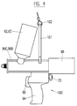
- Fig. 4 shows a portable metering and mixing appliance assembly 100 with a longitudinally slidingly adjustable and self locking suspension bracket 101 attached to upper tie rods 80C & 80D for connection to a suspension device such that the centre of gravity of the complete appliance is well below the point where a flexible suspension line 102 connects to the adjustable suspension bracket 101, thus ensuring a stable position of the unit yet allowing the appliance to move freely.
- the parallel containers 62 and 63 are vertical or are inclined towards the rear of the unit at an angle between 90° to 65° relative to the longitudinal pump axis.
- Fig. 4 further shows the handle 64 with trigger 65.
- the drive unit 66 is symbolized, which can be an electrical, pneumatic or manual drive unit.
- Figs. 5 & 6 show a retaining system for the metering pump assembly 1, with four tie rods 80A,80B,80C,80D and front plate 12 which attach the metering pump assembly to the drive unit front flange 11 as shown in Fig. 1.
- Fig. 6 shows an indicator rod 81 having an indicator 82 attached which indicates the volumetric output against scales 83A & 83B located on the rear sleeves 6 & 7.
- Indicator rod 81 also has a secondary function as that of controlling the metering stroke length by making contact with, and stopping against, a stroke spacer 85 which may be varied in length according to the required metering volume, the stroke spacer 85 being held in position by a quick release bracket 86.
- a third drive rod 87, Fig. 5 is optionally provided for a third metering pump assembly 88 for the metering of an additional minor component of chemical liquid, the position of which may be as shown or, for instance, the whole arrangement may be reversed with the third pump being above the other two.
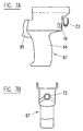
- Fig. 7A & 7B show side and rear views of the appliance handle assembly 67 comprising handle 64, trigger 65 and mode of operation selector switch 73 acting also as a push button in mode 1.
- the mode of operation selector switch 73 has approximately 120 to 180 degrees of switch movement between the two modes 1 and 2.
- position 1 of the selector switch as indicated by mode display 76, the metering plungers are driven forward by pulling the trigger 65 and stop upon release of the trigger 65, with the metering plungers being driven rearward for metering pump reload only via use of the selector switch 73 as a push button.
- position 2 (shown by dotted lines), the metering plungers are driven forward for metering by pulling of the trigger 65 and automatically driven rearwards when the trigger 65 is released.
- the invention provides for an improved and highly compact unit design utilising modular and interchangeable components for the mass production of compact and relatively low cost metering and mixing machines for multi-component reactive chemical systems with accurate performance and versatility of use.
- the invention also covers the need for the exact metering pump alignment relative to the drive rods, a method for attachment of containers to a compact side by side metering assembly yet allowing them to be attached parallel to each other, an optional third component pump which is usually required for very minor components, a visual metered output indicator in order that an operator may visually control a metered output, a mechanical adjustment for a specific shot volume and finally, an adjustable suspension bracket for hand held units such that it may be suspended and counterbalanced while allowing the unit to move freely with attached containers.
- the drive rods 14 and 16 may be actuated either by an electrically, pneumatically or manually operated drive.
Priority Applications (10)
| Application Number | Priority Date | Filing Date | Title |
|---|---|---|---|
| DE69620992T DE69620992T2 (de) | 1996-01-31 | 1996-01-31 | Vorrichtung zur Abgabe von wenigstens zwei Komponenten |
| DE69625096T DE69625096T2 (de) | 1996-01-31 | 1996-01-31 | Vorrichtung zur Abgabe von mindestens zwei Komponenten |
| ES00200174T ES2186611T3 (es) | 1996-01-31 | 1996-01-31 | Dispositivo para el suministro de por lo menos dos componentes. |
| EP00200174A EP0992292B1 (fr) | 1996-01-31 | 1996-01-31 | Dispositif pour distribuer au moins deux composants |
| EP96810066A EP0787535B1 (fr) | 1996-01-31 | 1996-01-31 | Dispositif pour distribuer au moins deux composants |
| ES96810066T ES2174046T3 (es) | 1996-01-31 | 1996-01-31 | Aparato de distribucion, por lo menos para dos componentes. |
| TW086101061A TW399027B (en) | 1996-01-31 | 1997-01-30 | Dispensing appliance for at least two components |
| US08/791,402 US6029857A (en) | 1996-01-31 | 1997-01-30 | Dispensing appliance for at least two components |
| KR1019970002806A KR970058789A (ko) | 1996-01-31 | 1997-01-30 | 2개 이상의 성분을 구비한 분배 장치 |
| JP01831397A JP3775875B2 (ja) | 1996-01-31 | 1997-01-31 | 分配装置 |
Applications Claiming Priority (1)
| Application Number | Priority Date | Filing Date | Title |
|---|---|---|---|
| EP96810066A EP0787535B1 (fr) | 1996-01-31 | 1996-01-31 | Dispositif pour distribuer au moins deux composants |
Related Child Applications (1)
| Application Number | Title | Priority Date | Filing Date |
|---|---|---|---|
| EP00200174A Division EP0992292B1 (fr) | 1996-01-31 | 1996-01-31 | Dispositif pour distribuer au moins deux composants |
Publications (2)
| Publication Number | Publication Date |
|---|---|
| EP0787535A1 true EP0787535A1 (fr) | 1997-08-06 |
| EP0787535B1 EP0787535B1 (fr) | 2002-05-02 |
Family
ID=8225542
Family Applications (2)
| Application Number | Title | Priority Date | Filing Date |
|---|---|---|---|
| EP96810066A Expired - Lifetime EP0787535B1 (fr) | 1996-01-31 | 1996-01-31 | Dispositif pour distribuer au moins deux composants |
| EP00200174A Expired - Lifetime EP0992292B1 (fr) | 1996-01-31 | 1996-01-31 | Dispositif pour distribuer au moins deux composants |
Family Applications After (1)
| Application Number | Title | Priority Date | Filing Date |
|---|---|---|---|
| EP00200174A Expired - Lifetime EP0992292B1 (fr) | 1996-01-31 | 1996-01-31 | Dispositif pour distribuer au moins deux composants |
Country Status (7)
| Country | Link |
|---|---|
| US (1) | US6029857A (fr) |
| EP (2) | EP0787535B1 (fr) |
| JP (1) | JP3775875B2 (fr) |
| KR (1) | KR970058789A (fr) |
| DE (2) | DE69625096T2 (fr) |
| ES (2) | ES2186611T3 (fr) |
| TW (1) | TW399027B (fr) |
Cited By (11)
| Publication number | Priority date | Publication date | Assignee | Title |
|---|---|---|---|---|
| CN102109046A (zh) * | 2009-12-24 | 2011-06-29 | 深圳市轴心自控技术有限公司 | 一种双组份计量阀 |
| EP2384822A1 (fr) | 2010-05-04 | 2011-11-09 | Heraeus Medical GmbH | Fermeture de cartouche et cartouche dotée d'une telle fermeture |
| EP2384821A2 (fr) | 2010-05-04 | 2011-11-09 | Heraeus Medical GmbH | Système de cartouche doté d'une cartouche de gaz comprimé |
| EP2384820A1 (fr) | 2010-05-04 | 2011-11-09 | Heraeus Medical GmbH | Système de cartouche et tuyau de sortie pour un tel système de cartouche |
| DE102010019220A1 (de) | 2010-05-04 | 2011-11-10 | Heraeus Medical Gmbh | Kartuschensystem mit verbundenen Förderkolben |
| EP2596873A2 (fr) | 2011-11-25 | 2013-05-29 | Heraeus Medical GmbH | Système de cartouche à plusieurs composants avec fermetures mobiles dans les cartouches |
| DE102012008815A1 (de) | 2012-05-07 | 2013-11-07 | Heraeus Medical Gmbh | Mischvorrichtung für Mehrkomponentensysteme |
| US8944296B2 (en) | 2010-05-04 | 2015-02-03 | Heraeus Medical Gmbh | Dispensing device for cartridges |
| US9073081B2 (en) | 2010-05-04 | 2015-07-07 | Heraeus Medical Gmbh | Dispensing device for pasty materials |
| US9168108B2 (en) | 2007-09-19 | 2015-10-27 | Kettenbach Gmbh & Co. Kg | Dispensing device |
| US10627001B2 (en) | 2018-06-29 | 2020-04-21 | Sulzer Mixpac Ag | Check valve system |
Families Citing this family (14)
| Publication number | Priority date | Publication date | Assignee | Title |
|---|---|---|---|---|
| US6715642B2 (en) | 2001-05-22 | 2004-04-06 | Access Business Group International Llc | Method and apparatus for blending and dispensing liquid compositions |
| AUPS229802A0 (en) * | 2002-05-07 | 2002-06-13 | Bremauer, Ben | Apparatus for mixing and/or testing small volumes of fluids |
| DE10312843B3 (de) | 2003-03-21 | 2004-11-11 | A. Kettenbach Gmbh & Co. Kg | Vorrichtung zum Ausbringen von Ein- oder Mehrkomponentenmassen und Ventilanordnung hierfür |
| DE10343575B4 (de) * | 2003-09-18 | 2006-06-29 | Hilti Ag | Auspressgerät mit Dosiervorrichtung |
| US6955277B2 (en) * | 2004-03-19 | 2005-10-18 | Smith Eric W | Dispensing device and method |
| KR100805439B1 (ko) * | 2006-10-02 | 2008-02-20 | 현대자동차주식회사 | 통합형 ccc 촉매 장치 |
| WO2008137181A1 (fr) | 2007-05-07 | 2008-11-13 | Clearly Superior, Inc | Epaississant pour produits alimentaires et son procédé de fabrication |
| US9085002B2 (en) * | 2011-05-19 | 2015-07-21 | Illinois Tool Works Inc. | Modular manifold adhesive gun |
| US9101156B2 (en) | 2013-03-15 | 2015-08-11 | Kent Precision Foods Group, Inc. | Thickener composition, thickened nutritive products, methods for preparing thickened nutritive products, and methods for providing nutrition |
| DE102016104190A1 (de) | 2016-03-08 | 2017-09-14 | Gerhard Brugger | Spender für die Ausgabe von flüssigen oder pastösen Substanzen |
| DE102019101640A1 (de) * | 2019-01-23 | 2020-07-23 | 3lmed GmbH | Kartusche |
| EP3825252A1 (fr) * | 2019-11-20 | 2021-05-26 | Hilti Aktiengesellschaft | Partie tête pour une cartouche et cartouche |
| US11751594B2 (en) | 2020-10-22 | 2023-09-12 | Grain Processing Corporation | Food thickener composition and method |
| CN115090217B (zh) * | 2022-07-21 | 2023-06-30 | 江苏亚振钻石有限公司 | 基于金刚石生产用配料定量机构 |
Citations (2)
| Publication number | Priority date | Publication date | Assignee | Title |
|---|---|---|---|---|
| EP0294672A1 (fr) * | 1987-06-10 | 1988-12-14 | Wilhelm A. Keller | Cartouche double pour mélange à deux composants |
| EP0607102A1 (fr) * | 1993-01-15 | 1994-07-20 | Wilhelm A. Keller | Appareil distributeur pour au moins deux composants |
Family Cites Families (8)
| Publication number | Priority date | Publication date | Assignee | Title |
|---|---|---|---|---|
| DE1454898B2 (de) * | 1965-02-19 | 1971-09-16 | Richard Zippel & Co, KG, 3440 Esch wege | Vorrichtung zum ausstossen einer einstellbaren genau dosier ten menge der komponenten eines fluessigen mehrkomponenten kunststoffes |
| US3570719A (en) * | 1968-07-02 | 1971-03-16 | Louis Schiff | Reagent mixing and dispensing apparatus |
| US4690306A (en) * | 1985-08-12 | 1987-09-01 | Ciba-Geigy Corporation | Dispensing device for storing and applying at least one liquid or pasty substance |
| US5092492A (en) * | 1990-01-26 | 1992-03-03 | Liquid Control Corporation | Liquid metering, mixing and dispensing gun |
| GB9109717D0 (en) * | 1991-05-03 | 1991-06-26 | Penn Laurence R | Improvements in or relating to a dispenser for liquid and a container for use with the dispenser |
| US5370273A (en) * | 1991-10-16 | 1994-12-06 | Minnesota Mining And Manufacturing Company | Multi-component applicator assembly |
| US5263614A (en) * | 1992-05-14 | 1993-11-23 | Jacobsen Kenneth H | Material dispensing tool for tubular cartridges |
| US5447987A (en) * | 1993-12-24 | 1995-09-05 | Shin-Etsu Chemical Co., Ltd. | Organopolysiloxane compositions |
-
1996
- 1996-01-31 DE DE69625096T patent/DE69625096T2/de not_active Expired - Lifetime
- 1996-01-31 DE DE69620992T patent/DE69620992T2/de not_active Expired - Lifetime
- 1996-01-31 EP EP96810066A patent/EP0787535B1/fr not_active Expired - Lifetime
- 1996-01-31 ES ES00200174T patent/ES2186611T3/es not_active Expired - Lifetime
- 1996-01-31 ES ES96810066T patent/ES2174046T3/es not_active Expired - Lifetime
- 1996-01-31 EP EP00200174A patent/EP0992292B1/fr not_active Expired - Lifetime
-
1997
- 1997-01-30 TW TW086101061A patent/TW399027B/zh not_active IP Right Cessation
- 1997-01-30 KR KR1019970002806A patent/KR970058789A/ko not_active Application Discontinuation
- 1997-01-30 US US08/791,402 patent/US6029857A/en not_active Expired - Lifetime
- 1997-01-31 JP JP01831397A patent/JP3775875B2/ja not_active Expired - Fee Related
Patent Citations (2)
| Publication number | Priority date | Publication date | Assignee | Title |
|---|---|---|---|---|
| EP0294672A1 (fr) * | 1987-06-10 | 1988-12-14 | Wilhelm A. Keller | Cartouche double pour mélange à deux composants |
| EP0607102A1 (fr) * | 1993-01-15 | 1994-07-20 | Wilhelm A. Keller | Appareil distributeur pour au moins deux composants |
Cited By (28)
| Publication number | Priority date | Publication date | Assignee | Title |
|---|---|---|---|---|
| US9168108B2 (en) | 2007-09-19 | 2015-10-27 | Kettenbach Gmbh & Co. Kg | Dispensing device |
| CN102109046A (zh) * | 2009-12-24 | 2011-06-29 | 深圳市轴心自控技术有限公司 | 一种双组份计量阀 |
| CN102109046B (zh) * | 2009-12-24 | 2014-04-16 | 深圳市轴心自控技术有限公司 | 一种双组份计量阀 |
| US8596499B2 (en) | 2010-05-04 | 2013-12-03 | Heraeus Medical Gmbh | Cartridge system with rotatable closure and dispensing tube |
| US9073081B2 (en) | 2010-05-04 | 2015-07-07 | Heraeus Medical Gmbh | Dispensing device for pasty materials |
| DE102010019223A1 (de) | 2010-05-04 | 2011-11-10 | Heraeus Medical Gmbh | Kartuschensystem mit Druckgaspatrone |
| DE102010019217A1 (de) | 2010-05-04 | 2011-11-10 | Heraeus Medical Gmbh | Kartuschensystem und Austragsrohr für ein solches Kartuschensystem |
| WO2011137971A1 (fr) | 2010-05-04 | 2011-11-10 | Heraeus Medical Gmbh | Système à cartouches comprenant des pistons assemblés |
| DE102010019219A1 (de) | 2010-05-04 | 2011-11-10 | Heraeus Medical Gmbh | Kartuschenverschluss und Kartusche mit einem solchen Verschluss |
| DE102010019223B4 (de) * | 2010-05-04 | 2012-02-16 | Heraeus Medical Gmbh | Kartuschensystem mit Druckgaspatrone |
| US9827030B2 (en) | 2010-05-04 | 2017-11-28 | Heraeus Medical Gmbh | Cartridge system having connected feed plungers |
| EP2384822A1 (fr) | 2010-05-04 | 2011-11-09 | Heraeus Medical GmbH | Fermeture de cartouche et cartouche dotée d'une telle fermeture |
| US9095871B2 (en) | 2010-05-04 | 2015-08-04 | Heraeus Medical Gmbh | Cartridge system and dispensing tube for said cartridge system |
| DE102010019220A1 (de) | 2010-05-04 | 2011-11-10 | Heraeus Medical Gmbh | Kartuschensystem mit verbundenen Förderkolben |
| EP2384820A1 (fr) | 2010-05-04 | 2011-11-09 | Heraeus Medical GmbH | Système de cartouche et tuyau de sortie pour un tel système de cartouche |
| DE102010019219B4 (de) * | 2010-05-04 | 2013-12-12 | Heraeus Medical Gmbh | Kartuschenverschluss und Kartusche mit einem solchen Verschluss |
| US8608030B2 (en) | 2010-05-04 | 2013-12-17 | Heraeus Medical Gmbh | Cartridge system with compressed gas cartridge |
| DE102010019217B4 (de) * | 2010-05-04 | 2014-01-16 | Heraeus Medical Gmbh | Kartuschensystem |
| EP2384821A2 (fr) | 2010-05-04 | 2011-11-09 | Heraeus Medical GmbH | Système de cartouche doté d'une cartouche de gaz comprimé |
| US8944296B2 (en) | 2010-05-04 | 2015-02-03 | Heraeus Medical Gmbh | Dispensing device for cartridges |
| US8986313B2 (en) | 2011-11-25 | 2015-03-24 | Heraeus Medical Gmbh | Multi-component cartridge system with shiftable closures in the cartridges |
| DE102011119357A1 (de) | 2011-11-25 | 2013-05-29 | Heraeus Medical Gmbh | Mehrkomponenten-Kartuschensystem mit verschiebbaren Verschlüssen in den Kartuschen |
| EP2596873A2 (fr) | 2011-11-25 | 2013-05-29 | Heraeus Medical GmbH | Système de cartouche à plusieurs composants avec fermetures mobiles dans les cartouches |
| US8992071B2 (en) | 2012-05-07 | 2015-03-31 | Heraeus Medical Gmbh | Mixing device for multi-component systems |
| EP2662150A2 (fr) | 2012-05-07 | 2013-11-13 | Heraeus Medical GmbH | Dispositif de mélange pour systèmes multicomposants |
| DE102012008815A1 (de) | 2012-05-07 | 2013-11-07 | Heraeus Medical Gmbh | Mischvorrichtung für Mehrkomponentensysteme |
| US10627001B2 (en) | 2018-06-29 | 2020-04-21 | Sulzer Mixpac Ag | Check valve system |
| US11920690B2 (en) | 2018-06-29 | 2024-03-05 | Medmix Switzerland Ag | Check valve system |
Also Published As
| Publication number | Publication date |
|---|---|
| TW399027B (en) | 2000-07-21 |
| KR970058789A (ko) | 1997-08-12 |
| EP0992292A2 (fr) | 2000-04-12 |
| ES2186611T3 (es) | 2003-05-16 |
| EP0787535B1 (fr) | 2002-05-02 |
| DE69620992T2 (de) | 2002-09-19 |
| DE69625096D1 (de) | 2003-01-09 |
| ES2174046T3 (es) | 2002-11-01 |
| EP0992292A3 (fr) | 2000-07-12 |
| JPH09216698A (ja) | 1997-08-19 |
| US6029857A (en) | 2000-02-29 |
| EP0992292B1 (fr) | 2002-11-27 |
| DE69620992D1 (de) | 2002-06-06 |
| DE69625096T2 (de) | 2003-05-08 |
| JP3775875B2 (ja) | 2006-05-17 |
Similar Documents
| Publication | Publication Date | Title |
|---|---|---|
| EP0787535B1 (fr) | Dispositif pour distribuer au moins deux composants | |
| EP0787534B1 (fr) | Dispositif de distribution d'au moins deux composants | |
| EP0607102B1 (fr) | Appareil distributeur pour au moins deux composants | |
| EP2585222B1 (fr) | Doseur de fluide a double pompe ayant une position de moteur ajustable | |
| US5092492A (en) | Liquid metering, mixing and dispensing gun | |
| US5127547A (en) | Metering and dispensing apparatus | |
| JPS6251764A (ja) | 制量ポンプ | |
| US6162030A (en) | Zero leakage valveless positive fluid displacement device | |
| EP0825422A1 (fr) | Dispositif de mesure | |
| EP0843786B1 (fr) | Pompe et son interface de raccordement rapide | |
| US20090068034A1 (en) | Pumping system with precise ratio output | |
| JP2000142895A (ja) | 遠隔供給源から適用場所への反応性樹脂配合物の移送システム | |
| US4650099A (en) | Liquid dispensing gun | |
| US20060060611A1 (en) | Metering pump, nozzle holder and system for the direct metering | |
| GB2214991A (en) | Improved double-acting pump | |
| RU2036437C1 (ru) | Плунжерный дозатор жидкостей | |
| US20040161349A1 (en) | Dosing pump | |
| GB1570009A (en) | Lubricating systems | |
| JPH07189891A (ja) | ポンプ | |
| AU2011257959A1 (en) | Improved injection moulding system | |
| HU193991B (en) | Multiple-purpose chemical industrial apparatus |
Legal Events
| Date | Code | Title | Description |
|---|---|---|---|
| PUAI | Public reference made under article 153(3) epc to a published international application that has entered the european phase |
Free format text: ORIGINAL CODE: 0009012 |
|
| AK | Designated contracting states |
Kind code of ref document: A1 Designated state(s): CH DE ES FR GB IT LI |
|
| AX | Request for extension of the european patent |
Free format text: LT;LV;SI |
|
| RBV | Designated contracting states (corrected) |
Designated state(s): CH DE ES FR GB IT LI |
|
| 17P | Request for examination filed |
Effective date: 19980114 |
|
| 17Q | First examination report despatched |
Effective date: 19990706 |
|
| DAX | Request for extension of the european patent (deleted) | ||
| GRAG | Despatch of communication of intention to grant |
Free format text: ORIGINAL CODE: EPIDOS AGRA |
|
| GRAG | Despatch of communication of intention to grant |
Free format text: ORIGINAL CODE: EPIDOS AGRA |
|
| GRAH | Despatch of communication of intention to grant a patent |
Free format text: ORIGINAL CODE: EPIDOS IGRA |
|
| REG | Reference to a national code |
Ref country code: GB Ref legal event code: IF02 |
|
| GRAH | Despatch of communication of intention to grant a patent |
Free format text: ORIGINAL CODE: EPIDOS IGRA |
|
| GRAA | (expected) grant |
Free format text: ORIGINAL CODE: 0009210 |
|
| AK | Designated contracting states |
Kind code of ref document: B1 Designated state(s): CH DE ES FR GB IT LI |
|
| REG | Reference to a national code |
Ref country code: GB Ref legal event code: FG4D |
|
| REG | Reference to a national code |
Ref country code: CH Ref legal event code: NV Representative=s name: AMMANN PATENTANWAELTE AG BERN Ref country code: CH Ref legal event code: EP |
|
| REF | Corresponds to: |
Ref document number: 69620992 Country of ref document: DE Date of ref document: 20020606 |
|
| ET | Fr: translation filed | ||
| REG | Reference to a national code |
Ref country code: ES Ref legal event code: FG2A Ref document number: 2174046 Country of ref document: ES Kind code of ref document: T3 |
|
| PLBE | No opposition filed within time limit |
Free format text: ORIGINAL CODE: 0009261 |
|
| STAA | Information on the status of an ep patent application or granted ep patent |
Free format text: STATUS: NO OPPOSITION FILED WITHIN TIME LIMIT |
|
| 26N | No opposition filed |
Effective date: 20030204 |
|
| REG | Reference to a national code |
Ref country code: GB Ref legal event code: 732E |
|
| REG | Reference to a national code |
Ref country code: FR Ref legal event code: TP |
|
| REG | Reference to a national code |
Ref country code: CH Ref legal event code: PUE Owner name: MIXPAC SYSTEMS AG Free format text: KELLER, WILHELM A.#OBSTGARTENWEG 9#CH-6402 MERLISCHACHEN (CH) -TRANSFER TO- MIXPAC SYSTEMS AG#GRUNDSTRASSE 12#6343 ROTKREUZ (CH) |
|
| PGFP | Annual fee paid to national office [announced via postgrant information from national office to epo] |
Ref country code: IT Payment date: 20120126 Year of fee payment: 17 |
|
| PGFP | Annual fee paid to national office [announced via postgrant information from national office to epo] |
Ref country code: DE Payment date: 20130122 Year of fee payment: 18 Ref country code: GB Payment date: 20130122 Year of fee payment: 18 Ref country code: FR Payment date: 20130213 Year of fee payment: 18 Ref country code: CH Payment date: 20130123 Year of fee payment: 18 Ref country code: ES Payment date: 20130128 Year of fee payment: 18 |
|
| REG | Reference to a national code |
Ref country code: DE Ref legal event code: R119 Ref document number: 69620992 Country of ref document: DE |
|
| REG | Reference to a national code |
Ref country code: CH Ref legal event code: PL |
|
| GBPC | Gb: european patent ceased through non-payment of renewal fee |
Effective date: 20140131 |
|
| REG | Reference to a national code |
Ref country code: DE Ref legal event code: R119 Ref document number: 69620992 Country of ref document: DE Effective date: 20140801 |
|
| PG25 | Lapsed in a contracting state [announced via postgrant information from national office to epo] |
Ref country code: LI Free format text: LAPSE BECAUSE OF NON-PAYMENT OF DUE FEES Effective date: 20140131 Ref country code: DE Free format text: LAPSE BECAUSE OF NON-PAYMENT OF DUE FEES Effective date: 20140801 Ref country code: CH Free format text: LAPSE BECAUSE OF NON-PAYMENT OF DUE FEES Effective date: 20140131 |
|
| REG | Reference to a national code |
Ref country code: FR Ref legal event code: ST Effective date: 20140930 |
|
| PG25 | Lapsed in a contracting state [announced via postgrant information from national office to epo] |
Ref country code: GB Free format text: LAPSE BECAUSE OF NON-PAYMENT OF DUE FEES Effective date: 20140131 Ref country code: FR Free format text: LAPSE BECAUSE OF NON-PAYMENT OF DUE FEES Effective date: 20140131 |
|
| REG | Reference to a national code |
Ref country code: ES Ref legal event code: FD2A Effective date: 20150327 |
|
| PG25 | Lapsed in a contracting state [announced via postgrant information from national office to epo] |
Ref country code: ES Free format text: LAPSE BECAUSE OF NON-PAYMENT OF DUE FEES Effective date: 20140201 |
|
| PG25 | Lapsed in a contracting state [announced via postgrant information from national office to epo] |
Ref country code: IT Free format text: LAPSE BECAUSE OF NON-PAYMENT OF DUE FEES Effective date: 20140131 |