EP0787346B1 - Aufbewahrungsbox zur archivierung eines daten- oder tonträgers - Google Patents
Aufbewahrungsbox zur archivierung eines daten- oder tonträgers Download PDFInfo
- Publication number
- EP0787346B1 EP0787346B1 EP95936496A EP95936496A EP0787346B1 EP 0787346 B1 EP0787346 B1 EP 0787346B1 EP 95936496 A EP95936496 A EP 95936496A EP 95936496 A EP95936496 A EP 95936496A EP 0787346 B1 EP0787346 B1 EP 0787346B1
- Authority
- EP
- European Patent Office
- Prior art keywords
- storage box
- base plate
- box according
- storage
- lateral walls
- Prior art date
- Legal status (The legal status is an assumption and is not a legal conclusion. Google has not performed a legal analysis and makes no representation as to the accuracy of the status listed.)
- Expired - Lifetime
Links
- 238000003860 storage Methods 0.000 title claims description 127
- 229920003023 plastic Polymers 0.000 claims description 16
- 239000004033 plastic Substances 0.000 claims description 15
- 239000000463 material Substances 0.000 claims description 4
- 239000011796 hollow space material Substances 0.000 claims 1
- 230000000295 complement effect Effects 0.000 description 11
- 238000002347 injection Methods 0.000 description 9
- 239000007924 injection Substances 0.000 description 9
- 238000004519 manufacturing process Methods 0.000 description 9
- 239000000969 carrier Substances 0.000 description 8
- 210000001331 nose Anatomy 0.000 description 3
- 238000012856 packing Methods 0.000 description 3
- 230000015572 biosynthetic process Effects 0.000 description 2
- 238000001746 injection moulding Methods 0.000 description 2
- 238000003780 insertion Methods 0.000 description 1
- 230000037431 insertion Effects 0.000 description 1
- 238000005304 joining Methods 0.000 description 1
- 238000003825 pressing Methods 0.000 description 1
Images



Classifications
-
- G—PHYSICS
- G11—INFORMATION STORAGE
- G11B—INFORMATION STORAGE BASED ON RELATIVE MOVEMENT BETWEEN RECORD CARRIER AND TRANSDUCER
- G11B33/00—Constructional parts, details or accessories not provided for in the other groups of this subclass
- G11B33/02—Cabinets; Cases; Stands; Disposition of apparatus therein or thereon
- G11B33/04—Cabinets; Cases; Stands; Disposition of apparatus therein or thereon modified to store record carriers
- G11B33/0405—Cabinets; Cases; Stands; Disposition of apparatus therein or thereon modified to store record carriers for storing discs
- G11B33/0461—Disc storage racks
- G11B33/0483—Disc storage racks for single disc boxes
Definitions
- the invention relates to a storage box for archiving a data or sound carrier with a Base plate, two side walls and a rear wall, which together a cuboid open on two sides Form cavity, the width, depth and height of which essentially the width, depth and height of an enclosure of the data or sound carrier, and with the Side walls arranged locking means for connecting at least two storage boxes.
- Such a storage box is made of, for example DE-92 14 174 U1 known.
- this storage box becomes the connection of two storage boxes with each other manufactured in that the side walls near their Upper edge in a weaker part several Have slots, in the correspondingly arranged, after internal hooks, each on the lower edges the side walls are arranged, can snap, so that a compartment housing made of several stacked lids can be formed. Furthermore, a slot extending over part of the same is provided in each side wall, as a result of which the side wall becomes somewhat resilient.
- DE-32 02 204 A1 is also a storage box known for archiving data or sound carriers, the by means of a snap connection with other storage boxes is connectable, the snap connection has a bead-like bar that fits into a bead-like Recess engages.
- Such a snap connection allows for easy connection of multiple storage boxes with each other, but it has the disadvantage that it dissolves easily, especially when on several interconnected storage boxes one Shear and / or torsional force is exerted, for example when applying pressure to one of several Storage boxes assembled on one of his towers Corners.
- connection goes from DE 32 02 204 A1 several storage boxes together by one Dovetail connection, one on the storage box arranged dovetail groove in one on one another storage box arranged opposite this Dovetail spring can be inserted.
- a dovetail connection has the Disadvantage that they are relatively expensive Merging two storage boxes requires and that, moreover, to make sure To ensure functioning, relatively expensive must be produced, which in the case of a plastic injection molded part again the demolding of several undercuts with additional sliders required.
- U1 is a storage box for information carriers with a box-shaped Housing, the cavity of which is the shape of the storage Information carrier is adapted and the common Use with other storage boxes on his Outside connecting devices that with Connecting devices of the same design, others Fit storage boxes in pairs, trained and are telescopable such that a number this storage box to a storage unit is known to be put together.
- connection between two storage boxes is also by pushing each other in pairs related dovetail grooves and dovetail springs accomplished which the already above have disadvantages described.
- the invention is therefore based on the object Storage box for archiving a data or To improve the sound carrier of the generic type in such a way that not only through appropriately trained locking means an easy connection of several storage boxes is possible with each other, but that the locking means for a particularly strong and secure connection convey, on the other hand easily manually without the aid additional auxiliary tools are releasable.
- This task is used for a storage box Archiving of a data or sound carrier at the beginning described type according to the invention solved in that the Side walls each on their upper, the bottom plate opposite end have an increase at which first locking means are arranged that the side walls each on its lower, facing the base plate End one, essentially complementary to the increases trained recess such that the Connection of the side wall with the base plate for Formation of a side opening in the side wall in Area of the recess is interrupted, and that for releasable attachment of at least two storage boxes to each other in the area of the recess on the side Boundary surfaces of the base plate with the first Interacting locking means arranged second locking means are.
- the arrangement of locking means on an increase each the upper end of the side walls facing away from the base plate and essentially forming one to increase complementary recess on the lower end of the side walls facing the base plate such that a side opening in the side wall in Area of the recess formed and the connection of the Sidewall is interrupted with the bottom plate, and that Arranging second locking means in the region of the recess on the lateral boundary surfaces of the base plate has the great advantage of having two or more storage boxes can be easily connected, and that these connections again without the help of Auxiliary tools can be solved.
- the side wall can be special easily deformed manually so that loosening the locking means is made possible.
- first and second Design locking means in any way.
- first Locking means openings and the second locking means in the Openable snap-in lugs are. This not only enables a firm and fast Connect two storage boxes, but above in addition, a particularly simple manufacture of the Recording box as a plastic injection molded part, because it is practical only undercuts occur in one direction, the one easy removal of the finished plastic injection molded part enable.
- the Openings holes and the locking lugs in the holes matching circular cylinders are at their lower, the Side wall facing away at least partially from are chamfered on the outside inwards in a wedge shape.
- This is a particularly quick snap second in the first locking means and thus a quick one Connect multiple storage boxes together and one later easy manual release of the snap connection without Using tools possible, the snap connection at the same time a fixed and not accidentally detachable connection of the receiving boxes with each other enables.
- first locking means as recesses complementary to the locking lugs to train.
- the locking lugs and the depressions preferably hemispherical to make it light To allow joining two storage boxes.
- the lateral boundary surfaces of the base plate in Area of the recesses on their side walls wedge-shaped lower side facing away from the outside inwards are continuously beveled, as this means that the Sidewalls trained increases particularly easily in the recesses complementary to them - while simultaneously snapping the first into the second Locking devices - can be introduced.
- Lugs protruding from the inside of the storage box be the distance from the bottom of the storage box
- ins Lugs protruding from the inside of the storage box be the distance from the bottom of the storage box
- Corresponds to the height of an envelope and its thickness in essentially the thickness of the bottom of a storage box corresponds.
- the bottom plate Storage box designed to complement the noses Provided recesses in which the noses Connection of two or more storage boxes arranged with each other in a particularly space-saving manner are.
- a data or sound carrier from the storage box enable is advantageously in the rear wall of the Storage box an opening for sliding out one Wrapping provided from the storage box.
- connection part is arranged breakable, which from the outside for the lateral connection of two storage boxes in cutouts arranged in the side walls is insertable.
- Every storage box also has a connecting part supplied with the one or more storage boxes can be connected side by side, which gives flexibility and design options the arrangement of several recording boxes significantly increased becomes.
- the storage box can in principle consist of different Materials and using different Manufacturing processes are manufactured. Especially but it is advantageous that the storage box Plastic injection molding is. This will create a simple, fast and inexpensive production enables. This is particularly so because in the case of the invention Storage box only practical undercuts in in a direction that is easy to remove from one required for the manufacturing process Form with the help of less well known per se Allows slide.
- the plastic is especially for aesthetic reasons transparent.
- feet can be attached to the storage box be arranged to this or several with each other connected storage boxes to be able to the feet have such friction with the support surface convey that the storage box or more Storage boxes difficult to rest on the surface on which they stand, are movable.
- Fig. 1 and Fig. 6 one includes preferably made of, in particular transparent, plastic existing, manufactured as a plastic injection molded part Storage box 1 essentially a base plate 3, two side walls 4, 5 and a rear wall 10.
- the outer surfaces of the side walls can easy grasping of the storage box 1 with a Corrugation may be provided, as shown in Fig. 1 is.
- the Side walls 4, 5 each on its upper, the bottom plate 3 opposite end an increase 9, at which first Latching means 11 in the form of circular openings are provided.
- the side walls 4, 5 each have at their lower, the Bottom plate 3 facing one end, to the elevations 9 recess 13 of essentially complementary design on.
- This recess 13 is formed such that the Side walls 4, 5 in the region of the recess 13 Connection of the side wall 4,5 with the base plate 3 for Formation of a lateral opening in the side wall 4,5 is interrupted.
- the second locking means 14 are in the first locking means 11, i.e. snap into the circular openings, after externally projecting locking lugs, which have the shape of in the Have openings matching circular cylinders that on their lower, the side wall 4, 5 facing away from each at least partially wedge-shaped from the outside inwards are tapered, as it is from the enlarged 5 shows.
- the second detent means 14 wedge-shaped bevel particularly well in the first locking means 11, if one Storage box 1 over another one located below it Storage box 1 placed and a downward facing Print vertically on the base plate 3 of the upper storage box 1 is exercised.
- the second latching means 14 can also be used again can be easily disengaged from the first locking means 11, if the side walls 4, 5 in the region of the recess 13 or the elevation 9 on which the side walls 4, 5 are not are attached to the base plate 3, something manually be deformed.
- Locking means 14 instead of the bottom wedge-shaped from the outside to the inside the second beveled circular cylinders Locking means 14, for example, also in the form of hemispherical projecting locking lugs be formed during the first locking means 11 as complementary Deepening can be provided.
- the arrangement of the second locking means 14 on a side Boundary surface 3a of the base plate 3 has in particular in the manufacture of the storage box 1 as Plastic injection molding the big advantage that only is an undercut in one direction, so that when demolding a plastic injection molded part finished storage box 1 only one minimal number of sliders known per se necessary are, which not only simplifies the manufacturing process, but also accelerated and consequent of which is cheaper.
- the lateral boundary surfaces 3a of the base plate 3 in The area of the recesses 13 are on their side walls 4, 5 facing away from the bottom each from the outside bevelled inwards so that this makes it easy to put the storage boxes together and thereby an easy snap-in of the first Latching means 11 in the second locking means 14 allows will (see Fig. 5).
- This additional connection in particular prevents several storage boxes arranged one above the other 1 by shear and / or torsional forces, for example if a print directed diagonally from a corner into the center on a whole tower of one above the other Storage boxes 1 is exercised, fall apart can.
- the projections 6 and increase Incisions 6a generally the stability of one another arranged storage boxes 1.
- the depth of the storage box 1 can be slightly smaller be as the depth of the envelope 16 of a data or Sound carrier. In this way, the wrapping of the easily grab data or sound carriers from the front and out pull out the receiving box 1, even if several Recording boxes 1 are arranged one above the other (cf. 7 and 8).
- FIGS. 1, 6 and 8 can be multiple storage boxes 1 due to the elevations 9 arranged first locking means 11 and the complementary recesses 13 and the second Latching means 14 particularly compact, i.e. with little Stack space on top of each other.
- the distance between two superimposed casings 16 essentially only on the thickness of the base plate 3 of a storage box 1 determined (see FIG. 8). That way a very large packing density of one another arranged, in individual storage boxes 1 a storage media stored safely and easily in reach the envelope 16.
- 6 to 8 show a further embodiment of a Storage box, in which on the elevations 9 of Side walls 4, 5 projecting into the interior of the receiving box 1 Lugs 18 are provided, whose thickness d is essentially corresponds to the thickness of the base plate 3 and the one accidental falling out of data or sound carriers in its envelope 16 from individual receiving boxes 1 prevent.
- FIG. 1, 2, 6, 7 has the rear wall 10 of the receiving box 1 a preferably centrally arranged opening 21, which for easy Sliding out an envelope 16 of a data or Sound carrier from the recording box 1 is used.
- fasteners for example in the form of rectangular Recesses 8a can be provided in the Connecting elements 8, for example on the rear wall 10 of the storage box 1 are arranged so that they can be broken out, for the lateral connection of two storage boxes 1 are insertable (see. Fig. 6 to 8).
Landscapes
- Details Of Rigid Or Semi-Rigid Containers (AREA)
- Packaging Of Annular Or Rod-Shaped Articles, Wearing Apparel, Cassettes, Or The Like (AREA)
- Packaging For Recording Disks (AREA)
- Toys (AREA)
- Particle Formation And Scattering Control In Inkjet Printers (AREA)
- Credit Cards Or The Like (AREA)
- Purses, Travelling Bags, Baskets, Or Suitcases (AREA)
- Stackable Containers (AREA)
Description
- Fig. 1
- schaubildlich mehrere übereinandergeordnete und miteinander verbundene Aufbewahrungsboxen einer ersten Ausführungsform zusammen mit einer weiteren einzelnen Aufnahmebox;
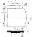
- Fig. 2a
- eine Draufsicht,
- Fig. 2b
- eine Seitenansicht von rechts,
- Fig. 2c
- eine teilweise geschnittene Seitenansicht von links,
- Fig. 2d
- eine teilweise geschnittene Hinteransicht einer ersten Ausführungsform einer erfindungsgemäßen Aufbewahrungsbox;
- Fig. 3
- eine vergrößerte Schnittdarstellung entlang der Linie III-III der Fig. 2b;
- Fig. 4
- eine vergrößerte Darstellung der in Fig. 2c mit IV bezeichneten Einzelheit;
- Fig. 5
- eine vergrößerte Darstellung der in Fig. 2d mit V bezeichneten Einzelheit;
- Fig. 6
- schaubildlich mehrere übereinander angeordnete und miteinander verbundene Aufbewahrungsboxen einer zweiten Ausführungsform zusammen mit einer weiteren einzelnen Aufnahmebox;
- Fig. 7
- eine Draufsicht auf die in Fig. 6 dargestellte zweite Ausführungsform einer erfindungsgemäßen Aufbewahrungsbox, in welcher sich die Umhüllung eines Daten- oder Tonträgers befindet und
- Fig. 8
- eine teilweise geschnittene Seitenansicht zweier miteinander verbundener Aufnahmeboxen einer in Fig. 6 und 7 dargestellten zweiten Ausführungsform mit darin befindlicher Umhüllung eines Daten- oder Tonträgers.
Claims (16)
- Aufbewahrungsbox zur Archivierung eines Daten- oder Tonträgers mit einer Bodenplatte (3), zwei Seitenwänden (4, 5) und einer Rückwand (10), welche zusammen einen nach zwei Seiten offenen quaderförmigen Hohlraum bilden, dessen Breite, Tiefe und Höhe im wesentlichen der Breite, Tiefe und Höhe einer Umhüllung des Daten- oder Tonträgers entspricht, und mit an den Seitenwänden angeordneten Ausnehmungen (13) sowie Rastmitteln zum Verbinden wenigstens zweier Aufbewahrungsboxen, dadurch gekennzeichnet, daß die Seitenwände (4, 5) jeweils an ihrem oberen, der Bodenplatte (3) abgewandten Ende eine Erhöhung (9) aufweisen, an welcher erste Rastmittel (11) angeordnet sind, daß die Seitenwände (4,5) jeweils an ihrem unteren, der Bodenplatte (3) zugewandten Ende eine, zu der Erhöhung (9) im wesentlichen komplementär ausgebildete Ausnehmung (13) derart aufweisen, daß die Verbindung der Seitenwand mit der Bodenplatte (3) zur Ausbildung einer seitlichen Öffnung in der Seitenwand (4, 5) im Bereich der Ausnehmung (13) unterbrochen ist, und daß zur lösbaren Befestigung wenigstens zweier Aufbewahrungsboxen (1) aneinander im Bereich der Ausnehmung (13) jeweils an seitlichen Begrenzungsflächen (3a) der Bodenplatte (3) mit den ersten Rastmitteln (11) zusammenwirkende zweite Rastmittel (14) angeordnet sind.
- Aufbewahrungsbox nach Anspruch 1, dadurch gekennzeichnet, daß die ersten Rastmittel (11) Öffnungen und die zweiten Rastmittel (14) in die Öffnungen einrastbare, nach außen vorspringende Rastnasen sind.
- Aufbewahrungsbox nach Anspruch 2, dadurch gekennzeichnet, daß die Öffnungen kreisförmig und die Rastnasen in die Öffnungen passende Kreiszylinder sind, die an Ihrer unteren, der Seitenwand abgewandten Seite wenigstens teilweise von außen nach innen keilförmig verlaufend abgeschrägt sind.
- Aufbewahrungsbox nach Anspruch 1 oder 2, dadurch gekennzeichnet, daß die ersten Rastmittel (11) zu den Rastnasen komplementär ausgebildete Vertiefungen sind.
- Aufbewahrungsbox nach Anspruch 4, dadurch gekennzeichnet, daß die Rastnasen und die Vertiefungen halbkugelförmig ausgebildet sind.
- Aufbewahrungsbox nach einem der voranstehenden Ansprüche, dadurch gekennzeichnet, daß die seitlichen Begrenzungsflächen (3a) der Bodenplatte (3) im Bereich der Ausnehmungen (13) an ihrer den Seitenwänden (4, 5) abgewandten unteren Seite jeweils von außen nach innen keilförmig verlaufend abgeschrägt sind.
- Aufbewahrungsbox nach einem der voranstehenden Ansprüche, dadurch gekennzeichnet, daß an den Oberseiten der Seitenwände (4, 5) wenigstens auf deren der Rückwand (10) abgewandten Seite neben der Erhöhung (8) ein Vorsprung (6) angeordnet ist, der in eine ihm gegenüberliegende und zu ihm im wesentlichen komplementär ausgebildete Ausnehmung (6a) in der Bodenplatte einer darüberliegend angeordneten Aufbewahrungsbox (1) einsteckbar ist.
- Aufbewahrungsbox nach einem der voranstehenden Ansprüche, dadurch gekennzeichnet, daß an der oberen, den Seitenwänden (4, 5) und der Rückwand (10) zugewandten Seite benachbart zu den Seitenwänden (4, 5) und der Rückwand (10) eine auf der Bodenplatte (3) umlaufende, einstückig mit der Bodenplatte (3) verbundene, rippenförmige Erhebung (20) angeordnet ist.
- Aufbewahrungsbox nach einem der voranstehenden Ansprüche, dadurch gekennzeichnet, daß zur Sicherung gegen Herausfallen einer in der Aufbewahrungsbox (1) aufgenommenen Umhüllung (16) an den Erhöhungen (9) ins Innere der Aufbewahrungsbox (1) ragende Nasen (18) angeordnet sind, deren Abstand von der Bodenplatte der Aufbewahrungsbox (1) der Höhe einer Umhüllung (16) entspricht und deren Dicke (d) im wesentlichen der Dicke der Bodenplatte (3) einer Aufbewahrungsbox (1) entspricht.
- Aufbewahrungsbox nach Anspruch 9, dadurch gekennzeichnet, daß in der Bodenplatte (3) der Aufbewahrungsbox (1) zu den Nasen (18) komplementär ausgebildete Ausnehmungen (19) vorgesehen sind.
- Aufbewahrungsbox nach einem der voranstehenden Ansprüche, dadurch gekennzeichnet, daß in der Rückwand (10) der Aufbewahrungsbox (1) eine Öffnung zum Herausschieben einer Umhüllung (16) aus der Aufbewahrungsbox (1) vorgesehen ist.
- Aufbewahrungsbox nach einem der voranstehenden Ansprüche, dadurch gekennzeichnet, daß wenigstens zwei nebeneinander angeordneten Aufbewahrungsboxen (1) seitlich miteinander verbindbar sind.
- Aufbewahrungsbox nach Anspruch 12, dadurch gekennzeichnet, daß an der Rückwand (10) ein Verbindungselement (8) herausbrechbar angeordnet ist, welches von außen zur seitlichen Verbindung zweier Aufbewahrungsboxen (1) in in den Seitenwänden (8a) angeordnete Ausschnitte einsteckbar ist.
- Aufbewahrungsbox nach einem der voranstehenden Ansprüche, dadurch gekennzeichnet, daß sie aus, insbesondere durchsichtigem Kunststoff besteht.
- Aufbewahrungsbox nach einem der voranstehenden Ansprüche, dadurch gekennzeichnet, daß sie ein Kunststoffspritzgußteil ist.
- Aufbewahrungsbox nach einem der voranstehenden Ansprüche, dadurch gekennzeichnet, daß an ihrer Unterseite Standfüße befestigbar sind.
Applications Claiming Priority (7)
| Application Number | Priority Date | Filing Date | Title |
|---|---|---|---|
| DE4437552 | 1994-10-20 | ||
| DE4437552 | 1994-10-20 | ||
| DE9416910U DE9416910U1 (de) | 1994-10-20 | 1994-10-20 | Aufbewahrungsbox zur Archivierung eines Daten- oder Tonträgers |
| DE9416910U | 1994-10-20 | ||
| DE19536879A DE19536879A1 (de) | 1994-10-20 | 1995-10-04 | Aufbewahrungsbox zur Archivierung eines Daten- oder Tonträgers |
| DE19536879 | 1995-10-04 | ||
| PCT/EP1995/004047 WO1996013036A1 (de) | 1994-10-20 | 1995-10-14 | Aufbewahrungsbox zur archivierung eines daten- oder tonträgers |
Publications (2)
| Publication Number | Publication Date |
|---|---|
| EP0787346A1 EP0787346A1 (de) | 1997-08-06 |
| EP0787346B1 true EP0787346B1 (de) | 1998-09-02 |
Family
ID=27206889
Family Applications (1)
| Application Number | Title | Priority Date | Filing Date |
|---|---|---|---|
| EP95936496A Expired - Lifetime EP0787346B1 (de) | 1994-10-20 | 1995-10-14 | Aufbewahrungsbox zur archivierung eines daten- oder tonträgers |
Country Status (6)
| Country | Link |
|---|---|
| EP (1) | EP0787346B1 (de) |
| JP (1) | JPH10507432A (de) |
| CN (1) | CN1169203A (de) |
| DE (3) | DE9416910U1 (de) |
| IL (1) | IL115683A0 (de) |
| WO (1) | WO1996013036A1 (de) |
Families Citing this family (5)
| Publication number | Priority date | Publication date | Assignee | Title |
|---|---|---|---|---|
| DE19851972A1 (de) * | 1998-11-02 | 2000-05-11 | Simon Schiesl | Stapeleinrichtung zur Archivierung von Standardhüllen für Daten- oder Tonträger des CD/Lasertyps |
| FR2789215B1 (fr) * | 1999-01-29 | 2001-04-20 | Roland Sauzet | Ensemble modulaire de conditionnement de disques compacts |
| WO2000045390A1 (fr) * | 1999-01-29 | 2000-08-03 | Roland Sauzet | Boitier de disque compact a tiroir |
| DE10326574B4 (de) * | 2003-06-12 | 2007-09-27 | Ifco Systems Gmbh | Transportbehältersystem und Aufsatz für ein Transportbehältersystem für Stückgut insbesondere für Obst und Gemüse |
| DE102016006537A1 (de) * | 2016-05-27 | 2017-11-30 | GM Global Technology Operations LLC (n. d. Gesetzen des Staates Delaware) | Verpackungssystem für Bauteile |
Family Cites Families (8)
| Publication number | Priority date | Publication date | Assignee | Title |
|---|---|---|---|---|
| DE3202204A1 (de) * | 1982-01-25 | 1983-08-04 | Hellmut 4800 Bielefeld Scheffler | Aufnahmebehaelter fuer aufzeichnungs-cassetten |
| GB2251596A (en) * | 1990-07-31 | 1992-07-15 | Martin Clapham | Stackable storage units |
| ES1015127Y (es) * | 1990-09-05 | 1994-05-16 | Davi Remedios Benitez | Archivador apilable con sistema de expulsion. |
| US5191983A (en) * | 1991-10-31 | 1993-03-09 | Rtc Industries, Inc. | Modular storage rack |
| DE9214174U1 (de) * | 1992-10-21 | 1994-02-24 | Florjancic, Peter, 82499 Wallgau | CD-Behälter |
| FR2699725B1 (fr) * | 1992-12-23 | 1995-02-03 | Handversion Sarl | Module unitaire de rangement, en particulier pour coffret de compact disque laser. |
| DE9316051U1 (de) * | 1993-10-21 | 1994-01-13 | Herbert Richter Metallwaren-Apparatebau GmbH & Co, 75180 Pforzheim | Diskettenbox |
| DE9317752U1 (de) * | 1993-11-19 | 1994-03-03 | Becker, Jens, 21244 Buchholz | Aufbewahrungsbehälter für Informationsträger mit einem kastenförmigen Gehäuse |
-
1994
- 1994-10-20 DE DE9416910U patent/DE9416910U1/de not_active Expired - Lifetime
-
1995
- 1995-10-04 DE DE19536879A patent/DE19536879A1/de not_active Withdrawn
- 1995-10-14 EP EP95936496A patent/EP0787346B1/de not_active Expired - Lifetime
- 1995-10-14 DE DE59503459T patent/DE59503459D1/de not_active Expired - Fee Related
- 1995-10-14 WO PCT/EP1995/004047 patent/WO1996013036A1/de not_active Ceased
- 1995-10-14 JP JP8513625A patent/JPH10507432A/ja active Pending
- 1995-10-14 CN CN95196718.5A patent/CN1169203A/zh active Pending
- 1995-10-19 IL IL11568395A patent/IL115683A0/xx unknown
Also Published As
| Publication number | Publication date |
|---|---|
| IL115683A0 (en) | 1996-01-19 |
| EP0787346A1 (de) | 1997-08-06 |
| DE59503459D1 (de) | 1998-10-08 |
| DE9416910U1 (de) | 1994-12-08 |
| CN1169203A (zh) | 1997-12-31 |
| WO1996013036A1 (de) | 1996-05-02 |
| DE19536879A1 (de) | 1996-05-02 |
| JPH10507432A (ja) | 1998-07-21 |
Similar Documents
| Publication | Publication Date | Title |
|---|---|---|
| DE2366590C2 (de) | Behälter zur Aufnahme einer Magnetbandkassette | |
| DE2213024C3 (de) | Spender für Rasierklingeneinheiten | |
| DE3410480C2 (de) | ||
| EP1922954A1 (de) | Ablage- und Sortiervorrichtung | |
| DE20108895U1 (de) | Kastenmodul für Gegenstände | |
| DE69209608T2 (de) | Modular aufgebauter Aufbewahrungsbehälter für Kassetten oder Kassettenblöcke | |
| DE69014722T3 (de) | Diebstahlsicherungsgehäuse, insbesondere für CD-Kassetten, Videokassetten und ähnliches. | |
| EP0640446A1 (de) | Gehäuse | |
| DE3106511A1 (de) | Aufbewahrungsbehaelter fuer tonband-kassetten und/oderschallplatten | |
| DE4009306C2 (de) | ||
| DE8901835U1 (de) | Modulcontainer für Einzel- bzw. Doppel- "compact-disc"-Kassetten mit versenkbaren Stegen sowie einer mit Hilfe von Biegefedern durch Drucktasten steuerbaren Ausstoßvorrichtung | |
| EP0787346A1 (de) | Aufbewahrungsbox zur archivierung eines daten- oder tonträgers | |
| WO1989011719A1 (fr) | Rangement pour supports d'enregistrement, tels que disquettes et/ou disques compacts | |
| EP0348787B2 (de) | Stapelbarer und in der Stapellage verriegelbarer Behälter | |
| EP0063250B1 (de) | Schubladen-Magazin, insbesondere für die Vorratshaltung und/oder Lagerung von Kleinteilen | |
| DE9315937U1 (de) | Aufbewahrungsbehälter zum Aufbewahren von im wesentlichen flachen Artikeln | |
| DE2517467C2 (de) | Abzweigkasten oder Abzweigdose für die Elektroinstallation | |
| DE60115311T2 (de) | Compaktdiskbehälter | |
| DE4007165A1 (de) | Kabelkanal, wie bruestungskanal, geraeteeinbaukanal o. dgl. | |
| DE3108696C2 (de) | Längsmagazin | |
| DE10255744B4 (de) | Vorrichtung zur Aufnahme von Standard-Datenträger-Kassetten | |
| DE10159382A1 (de) | Transportbehälter für Werkzeuge und/oder Werkstücke | |
| DE10201929B4 (de) | Behälter mit Schublade | |
| DE102015009734A1 (de) | Anreihbare Einzelverpackung | |
| DE202023101320U1 (de) | Behälter zur lösbaren Anbringung an einer Haltevorrichtung |
Legal Events
| Date | Code | Title | Description |
|---|---|---|---|
| PUAI | Public reference made under article 153(3) epc to a published international application that has entered the european phase |
Free format text: ORIGINAL CODE: 0009012 |
|
| 17P | Request for examination filed |
Effective date: 19970327 |
|
| AK | Designated contracting states |
Kind code of ref document: A1 Designated state(s): DE ES FR GB IT |
|
| GRAG | Despatch of communication of intention to grant |
Free format text: ORIGINAL CODE: EPIDOS AGRA |
|
| 17Q | First examination report despatched |
Effective date: 19971107 |
|
| GRAG | Despatch of communication of intention to grant |
Free format text: ORIGINAL CODE: EPIDOS AGRA |
|
| GRAH | Despatch of communication of intention to grant a patent |
Free format text: ORIGINAL CODE: EPIDOS IGRA |
|
| GRAH | Despatch of communication of intention to grant a patent |
Free format text: ORIGINAL CODE: EPIDOS IGRA |
|
| GRAA | (expected) grant |
Free format text: ORIGINAL CODE: 0009210 |
|
| AK | Designated contracting states |
Kind code of ref document: B1 Designated state(s): DE ES FR GB IT |
|
| PG25 | Lapsed in a contracting state [announced via postgrant information from national office to epo] |
Ref country code: IT Free format text: LAPSE BECAUSE OF FAILURE TO SUBMIT A TRANSLATION OF THE DESCRIPTION OR TO PAY THE FEE WITHIN THE PRESCRIBED TIME-LIMIT;WARNING: LAPSES OF ITALIAN PATENTS WITH EFFECTIVE DATE BEFORE 2007 MAY HAVE OCCURRED AT ANY TIME BEFORE 2007. THE CORRECT EFFECTIVE DATE MAY BE DIFFERENT FROM THE ONE RECORDED. Effective date: 19980902 Ref country code: GB Free format text: LAPSE BECAUSE OF FAILURE TO SUBMIT A TRANSLATION OF THE DESCRIPTION OR TO PAY THE FEE WITHIN THE PRESCRIBED TIME-LIMIT Effective date: 19980902 Ref country code: FR Free format text: LAPSE BECAUSE OF FAILURE TO SUBMIT A TRANSLATION OF THE DESCRIPTION OR TO PAY THE FEE WITHIN THE PRESCRIBED TIME-LIMIT Effective date: 19980902 Ref country code: ES Free format text: THE PATENT HAS BEEN ANNULLED BY A DECISION OF A NATIONAL AUTHORITY Effective date: 19980902 |
|
| REF | Corresponds to: |
Ref document number: 59503459 Country of ref document: DE Date of ref document: 19981008 |
|
| EN | Fr: translation not filed | ||
| GBV | Gb: ep patent (uk) treated as always having been void in accordance with gb section 77(7)/1977 [no translation filed] |
Effective date: 19980902 |
|
| PLBE | No opposition filed within time limit |
Free format text: ORIGINAL CODE: 0009261 |
|
| STAA | Information on the status of an ep patent application or granted ep patent |
Free format text: STATUS: NO OPPOSITION FILED WITHIN TIME LIMIT |
|
| 26N | No opposition filed | ||
| PGFP | Annual fee paid to national office [announced via postgrant information from national office to epo] |
Ref country code: DE Payment date: 20011020 Year of fee payment: 7 |
|
| PG25 | Lapsed in a contracting state [announced via postgrant information from national office to epo] |
Ref country code: DE Free format text: LAPSE BECAUSE OF NON-PAYMENT OF DUE FEES Effective date: 20030501 |