EP0786751B1 - Device for attaching the components of alarm systems - Google Patents
Device for attaching the components of alarm systems Download PDFInfo
- Publication number
- EP0786751B1 EP0786751B1 EP97100396A EP97100396A EP0786751B1 EP 0786751 B1 EP0786751 B1 EP 0786751B1 EP 97100396 A EP97100396 A EP 97100396A EP 97100396 A EP97100396 A EP 97100396A EP 0786751 B1 EP0786751 B1 EP 0786751B1
- Authority
- EP
- European Patent Office
- Prior art keywords
- housing
- alarm
- mounting means
- components
- monitoring
- Prior art date
- Legal status (The legal status is an assumption and is not a legal conclusion. Google has not performed a legal analysis and makes no representation as to the accuracy of the status listed.)
- Expired - Lifetime
Links
Images
Classifications
-
- G—PHYSICS
- G08—SIGNALLING
- G08B—SIGNALLING OR CALLING SYSTEMS; ORDER TELEGRAPHS; ALARM SYSTEMS
- G08B29/00—Checking or monitoring of signalling or alarm systems; Prevention or correction of operating errors, e.g. preventing unauthorised operation
- G08B29/02—Monitoring continuously signalling or alarm systems
- G08B29/04—Monitoring of the detection circuits
- G08B29/046—Monitoring of the detection circuits prevention of tampering with detection circuits
Definitions
- the invention relates to a device for fastening components of Alarm systems according to the preamble of claim 1, such as. B. from the Document US-A-4 631 526 is known.
- Alarm systems contain components for monitoring individual areas, For example, sensors on access doors, windows, etc., by the Alarm center are set down. These sensors are usually in housings arranged and attached to appropriate places, mostly walls.
- the Fastening takes place in known components so that the Fasteners, such as screws, when fully assembled Component are not accessible. For this purpose it is necessary that Open the housing during assembly and the assembled, closed Secure the housing against opening.
- the invention has for its object arranged in a housing Design components of alarm systems so that the attachment can be done quickly and without opening the housing, taking the components are protected against sabotage.
- the rear wall of the housing has a cutout a fastener, such as a screw can be performed.
- a fastener such as a screw
- Within the housing is an arrangement for monitoring the position of the Fastening means arranged, in particular a change in position of the Fasteners within the housing detects and an alarm signal delivers, which is preferably forwarded to the alarm center.
- the device according to the invention enables simple attachment of Components of an alarm system possible by the housing using the Recess in the fastener can be hooked.
- Fasteners can be used using screws or hooks are anchored in a wall, for example.
- the fastener is there not accessible because, for example, the screw head or the hook in the Protrude inside the housing.
- the arrangement exists to monitor the position of the fastener from a switch that is actuated through the recess when the fastener is carried out. In this way, the position, in particular the presence of the fastener in the housing supervised. Once the fastener is removed from the housing, i.e. when the housing is removed from the mounting location, the switch is back on opened or it changes its state, which triggers the alarm. False alarms can be avoided by switching the switch arranged or executed so that a slight movement does not lead to a Switch actuation leads.
- Another advantageous embodiment of the invention provides that the Arrangement for monitoring the position of the fastener indirectly or is arranged directly on the inside of the housing front wall. at Opening the case changes the relative position of the Position monitoring arrangement for the fastener and it becomes a Opening the housing is recognized and leads to an alarm.
- the housing in such a way that it can only be opened when not attached. This can For example, be achieved by the screws that hold the housing parts hold together, only accessible from the rear wall of the housing.
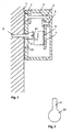
- the housing in which a component of an alarm system, for example a sensor for room monitoring, which is not shown in the figure, is arranged, consists of a housing rear wall 2 and a housing front wall 3, which are connected by means of a screw 4.
- the rear wall 2 of the housing has a recess 21, 22 through which a fastening means 8, in the present case a screw, can be passed.
- the recess 21, 22 has a lower part 22, the diameter of which is larger than the head of the screw 8 to be passed, and an upper part 21, the diameter of which is smaller than the screw head and larger than the diameter of the shaft the screw 8 is.
- the screw 8 is screwed, for example, into a wall 1, the screw head being at a distance from the wall 1.
- the housing 2, 3 is fastened to the screw by passing the lower part 22 of the recess over the head of the screw 8 and then lowering the housing so that the shaft of the screw 8 lies in the region of the upper part 21 of the recess.
- a switch 6 with a switching tongue 61 is arranged inside the housing. The switch is arranged within the housing so that the head of the screw actuates the switch tongue 61 when the housing is attached. If the housing is removed by an unauthorized person, an alarm signal is issued. A corresponding signal is preferably sent to the alarm center. If the housing is removed by the user, an alarm can be suppressed by disarming the alarm system entirely or only regarding the component.
- the switch 6, 61 can either be directly on the front wall of the housing be attached or, if the dimensions of the housing are not allow, by means of an insert 7 and a fastener 5 with the Be front wall connected.
Description
Die Erfindung betrifft eine Vorrichtung zur Befestigung von Komponenten von Alarmanlagen nach dem Oberbegriff des Anspruches 1, wie sie z. B. aus der Schrift US-A-4 631 526 bekannt ist.The invention relates to a device for fastening components of Alarm systems according to the preamble of claim 1, such as. B. from the Document US-A-4 631 526 is known.
Alarmanlagen beinhalten Komponenten zur Überwachung einzelner Bereiche, beispielsweise Sensoren an Zugangstüren, Fenstern usw., die von der Alarmzentrale abgesetzt sind. Diese Sensoren sind üblicherweise in Gehäusen angeordnet und an entsprechenden Stellen, meist Wänden, befestigt. Die Befestigung erfolgt bei bekannten Komponenten so, daß die Befestigungselemente, beispielsweise Schrauben, bei vollständig montierter Komponente nicht zugänglich sind. Zu diesem Zweck ist es notwendig, das Gehäuse bei der Montage zu öffnen und das montierte, geschlossene Gehäuse gegen ein Öffnen zu sichern.Alarm systems contain components for monitoring individual areas, For example, sensors on access doors, windows, etc., by the Alarm center are set down. These sensors are usually in housings arranged and attached to appropriate places, mostly walls. The Fastening takes place in known components so that the Fasteners, such as screws, when fully assembled Component are not accessible. For this purpose it is necessary that Open the housing during assembly and the assembled, closed Secure the housing against opening.
Der Erfindung liegt die Aufgabe zugrunde, in einem Gehäuse angeordnete Komponenten von Alarmanlagen so auszugestalten, daß die Befestigung schnell und ohne Öffnen des Gehäuses erfolgen kann, wobei die Komponenten gegen Sabotage geschützt sind.The invention has for its object arranged in a housing Design components of alarm systems so that the attachment can be done quickly and without opening the housing, taking the components are protected against sabotage.
Diese Aufgabe wird, ausgehend von den Merkmalen des Oberbegriffes des Anspruches 1 durch die kennzeichnenden Merkmale des Anspruches 1 gelöst. Vorteilhafte Ausgestaltungen der Erfindung sind in.den abhängigen Ansprüchen angegeben. This task is based on the features of the preamble of Claim 1 solved by the characterizing features of claim 1. Advantageous embodiments of the invention are in the dependent Claims specified.
Gemäß der Erfindung weist die Gehäuserückwand eine Aussparung auf, durch die ein Befestigungsmittel, beispielsweise eine Schraube geführt werden kann. Innerhalb des Gehäuses ist eine Anordnung zur Überwachung der Position des Befestigungsmittels angeordnet, die insbesondere eine Positionsänderung des Befestigungsmittels innerhalb des Gehäuses erkennt und ein Alarmsignal liefert, das vorzugsweise an die Alarmzentrale weitergeleitet wird.According to the invention, the rear wall of the housing has a cutout a fastener, such as a screw can be performed. Within the housing is an arrangement for monitoring the position of the Fastening means arranged, in particular a change in position of the Fasteners within the housing detects and an alarm signal delivers, which is preferably forwarded to the alarm center.
Durch die erfindungsgemäße Vorrichtung ist eine einfache Anbringung von Komponenten einer Alarmanlage möglich, indem das Gehäuse mittels der Aussparung in das Befestigungsmittel eingehängt werden kann. Als Befestigungsmittel können Schrauben oder Haken verwendet werden, die beispielsweise in einer Wand verankert sind. Das Befestigungsmittel ist dabei nicht zugänglich, da beispielsweise der Schraubenkopf oder der Haken in das Innere des Gehäuses ragen. Dort ist eine Anordnung zur Überwachung der Position des Befestigungsmittels angeordnet. Bei einer Änderung der Position oder der Abnahme des Gehäuses vom Befestigungsmittel wird ein Alarmsignal ausgegeben, so daß eine unbefugte Entfernung der Komponente nicht möglich ist.The device according to the invention enables simple attachment of Components of an alarm system possible by the housing using the Recess in the fastener can be hooked. As Fasteners can be used using screws or hooks are anchored in a wall, for example. The fastener is there not accessible because, for example, the screw head or the hook in the Protrude inside the housing. There is an arrangement for monitoring the Position of the fastener arranged. When the position changes or the removal of the housing from the fastener, an alarm signal issued so that unauthorized removal of the component is not possible is.
Gemäß einer vorteilhaften Ausgestaltung der Erfindung besteht die Anordnung zur Überwachung der Position des Befestigungsmittels aus einem Schalter, der bei Durchführung des Befestigungsmittels durch die Aussparung betätigt wird. Dadurch wird auf einfache und kostengünstige Weise die Position, insbesondere das Vorhandensein des Befestigungsmittels im Gehäuse überwacht. Sobald das Befestigungsmittel aus dem Gehäuse entfernt wird, d.h. bei Abnahme des Gehäuses vom Befestigungsort, wird der Schalter wieder geöffnet bzw. er ändert seinen Zustand, was zur Alarmauslösung führt. Fehlalarme können dadurch vermieden werden, daß der Schalter so angeordnet bzw. so ausgeführt wird, daß eine geringe Bewegung nicht zu einer Schalterbetätigung führt.According to an advantageous embodiment of the invention, the arrangement exists to monitor the position of the fastener from a switch that is actuated through the recess when the fastener is carried out. In this way, the position, in particular the presence of the fastener in the housing supervised. Once the fastener is removed from the housing, i.e. when the housing is removed from the mounting location, the switch is back on opened or it changes its state, which triggers the alarm. False alarms can be avoided by switching the switch arranged or executed so that a slight movement does not lead to a Switch actuation leads.
Eine weitere vorteilhafte Ausgestaltung der Erfindung sieht vor, daß die Anordnung zur Überwachung der Position des Befestigungsmittels mittelbar oder unmittelbar an der Innenseite der Gehäusevorderwand angeordnet ist. Bei Öffnen des Gehäuses verändert sich die relative Position der Positionsüberwachungsanordnung zum Befestigungsmittel und es wird ein Öffnen des Gehäuses erkannt und führt zur Alarmgabe.Another advantageous embodiment of the invention provides that the Arrangement for monitoring the position of the fastener indirectly or is arranged directly on the inside of the housing front wall. at Opening the case changes the relative position of the Position monitoring arrangement for the fastener and it becomes a Opening the housing is recognized and leads to an alarm.
Im weiteren hat es sich als vorteilhaft erwiesen, das Gehäuse so auszuführen, daß es nur im nicht befestigten Zustand geöffnet werden kann. Dies kann beispielsweise erreicht werden, indem die Schrauben, welche die Gehäuseteile zusammenhalten, nur von der Gehäuserückwand zugänglich sind.Furthermore, it has proven advantageous to design the housing in such a way that it can only be opened when not attached. This can For example, be achieved by the screws that hold the housing parts hold together, only accessible from the rear wall of the housing.
Im folgenden wird die Erfindung an Hand eines Ausführungsbeispiels gemäß
den Figuren 1 und 2 erläutert.
Es zeigen:
- Figur 1:
- einen Querschnitt der erfindungsgemäßen Vorrichtung und
- Figur 2:
- die Aussparung in Vorderansicht.
Show it:
- Figure 1:
- a cross section of the device according to the invention and
- Figure 2:
- the recess in front view.
Das Gehäuse, in dem eine Komponente einer Alarmanlage, beispielsweise ein
Sensor für Raumüberwachung, der in der Figur nicht dargestellt ist, angeordnet
ist, besteht aus einer Gehäuserückwand 2 und einer Gehäusevorderwand 3,
die mittels einer Schraube 4 verbunden sind.
Die Gehäuserückwand 2 weist eine Aussparung 21, 22 auf, durch die ein
Befestigungsmittel 8, im vorliegenden Fall eine Schraube, hindurchgeführt
werden kann.
Wie aus Figur 2 ersichtlich, weist die Aussparung 21, 22 einen unteren Teil 22,
dessen Durchmesser größer ist als der Kopf der hindurchzuführenden
Schraube 8 ist, und einen oberen Teil 21 auf, dessen Durchmesser kleiner als
der Schraubenkopf und größer als der Durchmesser des Schaftes des
Schraube 8 ist.
Die Schraube 8 ist beispielsweise in eine Wand 1 eingeschraubt, wobei der
Schraubenkopf einen Abstand zur Wand 1 aufweist. Das Gehäuse 2, 3 wird an
der Schraube befestigt, indem der untere Teil 22 der Aussparung über den
Kopf der Schraube 8 geführt wird und anschließend das Gehäuse abgesenkt
wird, so daß der Schaft der Schraube 8 im Bereich des oberen Teils 21 der
Aussparung liegt.
Im Inneren des Gehäuses ist gemäß dem Ausführungsbeispiel ein Schalter 6
mit einer Schaltzunge 61 angeordnet. Der Schalter ist innerhalb des Gehäuses
so angeordnet, daß bei Einhängen des Gehäuses der Kopf der Schraube die
Schalterzunge 61 betätigt. Bei Abnahme des Gehäuses durch einen
Unbefugten wird ein Alarmsignal ausgegeben.
Dabei wird vorzugsweise ein entsprechendes Signal an die Alarmzentrale
gegeben. Im Fall der Abnahme des Gehäuses durch den Benutzer kann ein
Alarm unterdrückt werden, indem die Alarmanlage ganz oder nur die
Komponente betreffend unscharfgeschaltet wird.The housing, in which a component of an alarm system, for example a sensor for room monitoring, which is not shown in the figure, is arranged, consists of a housing
The
As can be seen from FIG. 2, the
The
According to the exemplary embodiment, a
A corresponding signal is preferably sent to the alarm center. If the housing is removed by the user, an alarm can be suppressed by disarming the alarm system entirely or only regarding the component.
Der Schalter 6, 61 kann entweder direkt an der Gehäusevorderwand
angebracht sein oder, falls die Abmessungen des Gehäuses dies nicht
zulassen, mittels eines Einsatzes 7 und einem Befestigungsmittel 5 mit der
Gehäusevorderwand verbunden sein.The
Durch die erfindungsgemäße Vorrichtung können Komponenten einer Alarmanlage schnell und damit kostengünstig angebracht und beispielsweise für Servicezwecke entfernt werden, wobei der Schutz gegen eine unberechtigte Entfernung der Komponente gegenüber bekannten Lösungen noch erhöht wurde.With the device according to the invention, components of a Alarm system quickly and therefore inexpensively attached and for example removed for service purposes, protecting against an unauthorized Component removal increased compared to known solutions has been.
Claims (4)
- Device for mounting components of alarm systems that are operated remotely from the alarm centre and are disposed in a housing (2, 3), characterized in that the housing can be suspended by means of a cutout (21, 22) in the housing rear wall on a mounting means (8), an arrangement (6, 61) for monitoring the position of the mounting means (8) is disposed within the housing (2, 3), and, after the suspension, an alarm signal is emitted in the event of a change in position of the mounting means (8) within the housing (2, 3).
- Device according to Claim 1, characterized in that the arrangement (6, 61) for monitoring the position of the mounting means (8) comprises a switch that is disposed in such a way that it is actuated if the mounting means (8) is fed through the cutout (21, 22).
- Device according to Claim 1 or 2, characterized in that the arrangement (6, 61) for monitoring the position of the mounting means (8) is disposed indirectly or directly on the inside of the housing front wall (3) in order also to detect any opening of the housing (2, 3).
- Device according to any of Claims 1 to 3, characterized in that the housing (2, 3) is designed in such a way that it can be opened only in the unmounted state.
Applications Claiming Priority (2)
| Application Number | Priority Date | Filing Date | Title |
|---|---|---|---|
| DE19603067A DE19603067A1 (en) | 1996-01-29 | 1996-01-29 | Device for fastening components of alarm systems |
| DE19603067 | 1996-01-29 |
Publications (3)
| Publication Number | Publication Date |
|---|---|
| EP0786751A2 EP0786751A2 (en) | 1997-07-30 |
| EP0786751A3 EP0786751A3 (en) | 1999-08-04 |
| EP0786751B1 true EP0786751B1 (en) | 2003-08-20 |
Family
ID=7783940
Family Applications (1)
| Application Number | Title | Priority Date | Filing Date |
|---|---|---|---|
| EP97100396A Expired - Lifetime EP0786751B1 (en) | 1996-01-29 | 1997-01-11 | Device for attaching the components of alarm systems |
Country Status (2)
| Country | Link |
|---|---|
| EP (1) | EP0786751B1 (en) |
| DE (2) | DE19603067A1 (en) |
Cited By (1)
| Publication number | Priority date | Publication date | Assignee | Title |
|---|---|---|---|---|
| EP1884750A2 (en) * | 2006-07-25 | 2008-02-06 | Lince Italia S.p.A. | Supporting hanger, in particular for sensors of alarm systems, and related sensor |
Families Citing this family (9)
| Publication number | Priority date | Publication date | Assignee | Title |
|---|---|---|---|---|
| DE19632287B4 (en) * | 1996-08-09 | 2007-02-22 | Robert Bosch Gmbh | External signal transmitter and method for triggering a pre-alarm with an external signal transmitter |
| IT1284922B1 (en) * | 1996-10-07 | 1998-05-28 | Bticino Spa | ELECTRIC APPLIANCE FOR BURGLAR ALARM SYSTEMS OR SIMILAR |
| DE59907541D1 (en) * | 1999-03-08 | 2003-12-04 | Siemens Building Tech Ag | Housing for a hazard detector |
| EP1227452A1 (en) | 2001-01-19 | 2002-07-31 | Siemens Building Technologies AG | Security system and hazard warning device for monitoring risk parameters |
| FR2829271B1 (en) * | 2001-08-28 | 2005-12-02 | J C Decaux | TELESURVEILLANCE SYSTEM FOR LUMINOUS DISPLAY DEVICE |
| WO2004068431A1 (en) | 2003-01-30 | 2004-08-12 | Matsushita Electric Industrial Co., Ltd. | Abnormality detection device and information apparatus using the same |
| US20090271144A1 (en) * | 2008-04-29 | 2009-10-29 | Radio Systemes Ingenierie Video Technologies (Sa) | Detection unit protected against detachment and/or forced entry and system that comprises at least one such unit |
| RU2627557C1 (en) * | 2016-10-10 | 2017-08-08 | Общество с ограниченной ответственностью "Элеста" | Signalling device |
| PT3499479T (en) * | 2017-12-13 | 2021-06-18 | Verisure Sarl | An alarm peripheral with an anti-tampering arrangement and an anti-tampering arrangement |
Family Cites Families (9)
| Publication number | Priority date | Publication date | Assignee | Title |
|---|---|---|---|---|
| FR1493714A (en) * | 1966-07-21 | 1967-09-01 | Electrical safety switch device actuated by an assembly member, in particular by bolt | |
| US4092641A (en) * | 1976-07-06 | 1978-05-30 | Statitrol Corporation | Security interlock switch system for smoke detectors and the like |
| US4236148A (en) * | 1979-03-19 | 1980-11-25 | Crown Auto Top Manufacturing Co. | Theft deterring and signalling device for portable fire extinguishers |
| US4385288A (en) * | 1981-05-04 | 1983-05-24 | Fifth Dimension, Inc. | Motion responsive alarm system |
| US4631526A (en) * | 1982-06-10 | 1986-12-23 | Automated Security Holdings, Ltd. | Theft proof alarm bell assembly |
| US4542337A (en) * | 1982-09-30 | 1985-09-17 | Honeywell Inc. | Electro-mechanical anti-tampering device for electric meters |
| DE3308455A1 (en) * | 1983-03-10 | 1984-09-13 | Hans-Joachim 5810 Witten Becker | Alarm system for protecting a building |
| DE3420439A1 (en) * | 1984-06-01 | 1985-12-05 | Krauskopf GmbH & Co Elektrotechnik KG, 6301 Biebertal | Housings for surveillance systems |
| FR2602078A1 (en) * | 1986-07-24 | 1988-01-29 | Signal Vision Sa | Alarm siren with a device for inhibiting the self-protection safety measures |
-
1996
- 1996-01-29 DE DE19603067A patent/DE19603067A1/en not_active Withdrawn
-
1997
- 1997-01-11 EP EP97100396A patent/EP0786751B1/en not_active Expired - Lifetime
- 1997-01-11 DE DE59710589T patent/DE59710589D1/en not_active Expired - Lifetime
Cited By (2)
| Publication number | Priority date | Publication date | Assignee | Title |
|---|---|---|---|---|
| EP1884750A2 (en) * | 2006-07-25 | 2008-02-06 | Lince Italia S.p.A. | Supporting hanger, in particular for sensors of alarm systems, and related sensor |
| EP1884750A3 (en) * | 2006-07-25 | 2011-03-02 | Lince Italia S.p.A. | Supporting hanger, in particular for sensors of alarm systems, and related sensor |
Also Published As
| Publication number | Publication date |
|---|---|
| DE59710589D1 (en) | 2003-09-25 |
| EP0786751A2 (en) | 1997-07-30 |
| DE19603067A1 (en) | 1997-07-31 |
| EP0786751A3 (en) | 1999-08-04 |
Similar Documents
| Publication | Publication Date | Title |
|---|---|---|
| DE602005005926T2 (en) | MAGNETIC CONTACT MANIPULATION PROTECTION SWITCH FOR SAFETY ACCESSORIES | |
| EP0786751B1 (en) | Device for attaching the components of alarm systems | |
| DE2704478C2 (en) | Anti-theft system for automobiles | |
| EP1037184B1 (en) | Casing for hazard warning device | |
| EP0720136B1 (en) | Device for arming an alarm system and for monitoring an entry door | |
| DE4105485A1 (en) | DEVICE FOR DELAYING THE OPENING OF A DOOR | |
| DE102017103723A1 (en) | Safety swivel handle assembly | |
| DE4339318C1 (en) | Device for arming a radio alarm system | |
| EP1938292A1 (en) | Danger detector | |
| DE2223662A1 (en) | Burglar and theft alarm device | |
| DE4411290C2 (en) | Device for receiving a sensor | |
| EP3260634B1 (en) | Device for securing and/or monitoring closure elements | |
| EP1110189B1 (en) | Situation detecting device for recognizing the blocking of doors, gates and the like | |
| EP0585735B1 (en) | Retention lock for security lock cylinder | |
| EP3535739B1 (en) | Security device for monitoring the position of a wing | |
| DE602004008119T2 (en) | MULTIFUNCTIONAL DECOUPLING DEVICE FOR MAGNETIC THEFT CONTROL | |
| DE3718339A1 (en) | Key-operated switch or key-operated push button | |
| EP1580363B1 (en) | Device for securing or surveillance of emergency exits or similar | |
| CH674876A5 (en) | ||
| EP0616307B1 (en) | Intrusion detector | |
| EP0757339B1 (en) | Intrusion alarm | |
| DE10253503B4 (en) | Capacitive sensor and door handle unit | |
| DE3502759C2 (en) | Burglar alarm device for an up-and-over garage door | |
| DE3631235A1 (en) | Auxiliary device for arresting motor-vehicle doors in a part-open mounting position | |
| EP0942128B1 (en) | Device for a burglar alarm installation |
Legal Events
| Date | Code | Title | Description |
|---|---|---|---|
| PUAI | Public reference made under article 153(3) epc to a published international application that has entered the european phase |
Free format text: ORIGINAL CODE: 0009012 |
|
| AK | Designated contracting states |
Kind code of ref document: A2 Designated state(s): DE FR GB IT |
|
| PUAL | Search report despatched |
Free format text: ORIGINAL CODE: 0009013 |
|
| AK | Designated contracting states |
Kind code of ref document: A3 Designated state(s): DE FR GB IT |
|
| 17P | Request for examination filed |
Effective date: 20000113 |
|
| RAP1 | Party data changed (applicant data changed or rights of an application transferred) |
Owner name: GRUNDIG AKTIENGESELLSCHAFT |
|
| 17Q | First examination report despatched |
Effective date: 20020612 |
|
| GRAH | Despatch of communication of intention to grant a patent |
Free format text: ORIGINAL CODE: EPIDOS IGRA |
|
| GRAH | Despatch of communication of intention to grant a patent |
Free format text: ORIGINAL CODE: EPIDOS IGRA |
|
| GRAA | (expected) grant |
Free format text: ORIGINAL CODE: 0009210 |
|
| AK | Designated contracting states |
Designated state(s): DE FR GB IT |
|
| REG | Reference to a national code |
Ref country code: GB Ref legal event code: FG4D Free format text: NOT ENGLISH |
|
| REF | Corresponds to: |
Ref document number: 59710589 Country of ref document: DE Date of ref document: 20030925 Kind code of ref document: P |
|
| GBT | Gb: translation of ep patent filed (gb section 77(6)(a)/1977) |
Effective date: 20040120 |
|
| ET | Fr: translation filed | ||
| PLBE | No opposition filed within time limit |
Free format text: ORIGINAL CODE: 0009261 |
|
| STAA | Information on the status of an ep patent application or granted ep patent |
Free format text: STATUS: NO OPPOSITION FILED WITHIN TIME LIMIT |
|
| 26N | No opposition filed |
Effective date: 20040524 |
|
| REG | Reference to a national code |
Ref country code: GB Ref legal event code: 732E |
|
| REG | Reference to a national code |
Ref country code: FR Ref legal event code: TP |
|
| REG | Reference to a national code |
Ref country code: FR Ref legal event code: PLFP Year of fee payment: 20 |
|
| REG | Reference to a national code |
Ref country code: DE Ref legal event code: R082 Ref document number: 59710589 Country of ref document: DE |
|
| PGFP | Annual fee paid to national office [announced via postgrant information from national office to epo] |
Ref country code: DE Payment date: 20160201 Year of fee payment: 20 Ref country code: IT Payment date: 20160129 Year of fee payment: 20 |
|
| PGFP | Annual fee paid to national office [announced via postgrant information from national office to epo] |
Ref country code: FR Payment date: 20160128 Year of fee payment: 20 Ref country code: GB Payment date: 20160127 Year of fee payment: 20 |
|
| REG | Reference to a national code |
Ref country code: DE Ref legal event code: R071 Ref document number: 59710589 Country of ref document: DE |
|
| REG | Reference to a national code |
Ref country code: GB Ref legal event code: PE20 Expiry date: 20170110 |
|
| PG25 | Lapsed in a contracting state [announced via postgrant information from national office to epo] |
Ref country code: GB Free format text: LAPSE BECAUSE OF EXPIRATION OF PROTECTION Effective date: 20170110 |