EP0786693B1 - Film photographique - Google Patents
Film photographique Download PDFInfo
- Publication number
- EP0786693B1 EP0786693B1 EP97100977A EP97100977A EP0786693B1 EP 0786693 B1 EP0786693 B1 EP 0786693B1 EP 97100977 A EP97100977 A EP 97100977A EP 97100977 A EP97100977 A EP 97100977A EP 0786693 B1 EP0786693 B1 EP 0786693B1
- Authority
- EP
- European Patent Office
- Prior art keywords
- line
- photo filmstrip
- photo
- lateral edges
- filmstrip
- Prior art date
- Legal status (The legal status is an assumption and is not a legal conclusion. Google has not performed a legal analysis and makes no representation as to the accuracy of the status listed.)
- Expired - Lifetime
Links
Images


Classifications
-
- G—PHYSICS
- G03—PHOTOGRAPHY; CINEMATOGRAPHY; ANALOGOUS TECHNIQUES USING WAVES OTHER THAN OPTICAL WAVES; ELECTROGRAPHY; HOLOGRAPHY
- G03C—PHOTOSENSITIVE MATERIALS FOR PHOTOGRAPHIC PURPOSES; PHOTOGRAPHIC PROCESSES, e.g. CINE, X-RAY, COLOUR, STEREO-PHOTOGRAPHIC PROCESSES; AUXILIARY PROCESSES IN PHOTOGRAPHY
- G03C1/00—Photosensitive materials
- G03C1/76—Photosensitive materials characterised by the base or auxiliary layers
- G03C1/765—Photosensitive materials characterised by the base or auxiliary layers characterised by the shape of the base, e.g. arrangement of perforations, jags
Definitions
- the present invention relates to a photographic film. More particularly, the present invention relates to a photographic film which is wound about a spool and preferably contained in a photo film cassette.
- Photographic film of 135 type has two trains of perforations arranged along respective lateral edges and at a regular pitch, and contained in a cassette shell of a photo film cassette having light shielding capacity.
- a trailer of the photo film is connected to a spool in the cassette shell, and is contained in the cassette shell after winding the photo film in a roll form.
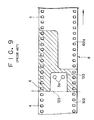
- a trailer of a photo filmstrip 102 is illustrated. Perforations 4 are arranged at a regular pitch P.
- a trailer of the photo filmstrip 102 has a retainer portion 103, which is narrower than the remaining portion of the photo filmstrip 102.
- the retainer portion 103 has a length A and a width W.
- To define the length A of the retainer portion 103 lateral edges are cut along a first line 120 being perpendicular to the lateral edges.
- the first line 120 has a position lying between the perforations 4.
- the trailer is cut along second and third lines 121a and 121b being parallel to the lateral edges.
- Two retaining holes 3a are formed in the retainer portion 103.
- the retainer portion 103 is inserted in a slot 6 in a spool core 5, retaining claws 7 inside the slot 6 are engaged with the retaining holes 3a.
- the trailer is connected to the spool core 5, which is rotated in orienting the emulsion surface toward the spool core 5.
- the photo filmstrip 102 is wound on the spool core 5 in a roll form between flanges 5a.
- continuous photo film 8 for producing the photo filmstrip 102 is illustrated.
- the continuous photo film 8 is conveyed in the direction of the arrow at an amount as much as predetermined, the continuous photo film 8 is stopped and a cutter or trimmer is operated for forming a leader of a preceding photo filmstrip 102a and the trailer of the photo filmstrip 102 of Fig. 8, while eliminating a waste of the photo film.
- a pair of retaining holes 3a are formed by the cutter at the same time.
- the first line 120 has a position between the perforations.
- the photo filmstrip 102 meets t2 ⁇ t, where t is an interval between the perforations 4, and t2 is an interval between the first line 120 and one of the perforations 4 the closest to the end of the trailer.
- a shape of the cutter for shaping both the trailer of the photo filmstrip 102 and the leader of the photo filmstrip 102a is determined by considering the position of the first line 120.
- the photo filmstrip 102 about the spool core 5 is contained in a cassette shell light-tightly (See Figs. 3 and 4). Initially the leader of the photo filmstrip 102 is protruded from a photo film passage port. To load a camera with the photo filmstrip 102, the leader is manually picked and pulled as much as required. An end of the leader is fitted on a take-up spool of the camera. If a camera having an auto-loading mechanism is used, the leader end is placed near to the take-up spool suitably.
- a user may rotate the spool core 5 opposite to a direction of photo film winding, with incidental intention to draw out the leader as much as required. If the leader is drawn out longer than required, the spool core 5 can be rotated in the winding direction for the purpose of winding back a surplus portion of the leader. If the user is unaccustomed to the use of the photo film cassette, he or she is likely to rotate the spool core 5 opposite to the winding direction. As the leader of the photo filmstrip 102 is in frictional contact with light-trapping fabric in the passage port, the roll of the photo filmstrip 102 becomes loosed inside the cassette about the spool core 5 being rotated. A gap L is formed between the spool core 5 and an innermost one of the turns of the photo filmstrip 102 (See Fig. 6).
- the spool core 5 is rotated further in the direction opposite to the direction of winding of the photo filmstrip 102.
- a portion of the photo filmstrip 102 protruded from the slot 6 is pressed by force in a direction of orienting the emulsion surface convexly.
- a point H lying on the first line 120 is indicated in Fig. 10A. The portion at the point H is pushed by an open edge of the slot 6, so that the photo filmstrip 102 receives strong force in the opposite rotational direction inside the gap L (See Fig. 6).
- the photo filmstrip 102 kept in the roll form has irresistible tendency of maintaining a curl in a longitudinal direction.
- the photo filmstrip 102 also has a curling tendency in a width direction like an archway.
- the portions at the first line 120 flex or bend as illustrated in Fig. 10B. Stress occurs in directions of the arrows in the drawing at the perforations 4.
- the photo filmstrip 102 is likely to break from a corner of one of the perforations 4 along the broken line indicated in the drawing, only upon small reverse rotation of the spool core 5 with occurrence of the gap L (See Fig. 6).
- Fig. 11 is a graph of a condition of breakage of the photo filmstrip 102 upon reverse winding of the photo filmstrip 102 having the above-described shape.
- a horizontal axis is determined to take the available frame number of the photo filmstrip 102, or the maximum number of frames photographable to the photo filmstrip 102.
- a right-hand vertical axis is determined to take bending force BF (in grams) applied to the innermost turn of the photo filmstrip 102 in the opposite rotational direction.
- a left-hand vertical axis is determined to take the gap L (in mm).
- a linear velocity of rotation for reverse winding of the photo filmstrip 102 is 500 mm/sec.
- the gap L decreased according to an increase of the available frame number, and that the bending force BF increases according to the increase of the available frame number. If the photo filmstrip 102 has the gap L being small due to smallness of the available frame number, it is difficult for the photo filmstrip 102 to bend back upon reverse rotation of the spool core 5, so that the bending force BF applied to the photo filmstrip 102 is great. The greatness of the bending force BF is remarkable when the photo filmstrip 102 has the available frame number as great as 31-33 frames. Approximately 20 % or more of the photo filmstrip 102 of this length is broken and becomes unusable. The bending force BF is much greater if the photo filmstrip 102 has the available frame number as great as 34-36 frames. Approximately 70 % or more of the photo filmstrip 102 of this length is broken.
- an object of the present invention is to provide a photographic film which is wound about a spool and contained in a photo film cassette, and is prevented from being broken away from the spool even upon inadvertent reverse rotation of the spool.
- a photo filmstrip has plural rectangular perforations are arranged along each of lateral edges and at a regular interval.
- the photo filmstrip is wound about a spool in a roll form with a trailer thereof wound inwards.
- the photo filmstrip has a retainer portion adapted to retention on the spool, formed at a smaller width like a tongue by cutting the lateral edges of the trailer in an L-shape along first, second and third lines.
- the first line being substantially perpendicular to the lateral edges.
- the second and third lines are substantially parallel to the lateral edges.
- the first line lies on one of the perforations having been arranged before forming the retainer portion along the lateral edges.
- the retainer portion is preferably retained in insertion into a slot formed in the spool to extend in an axial direction.
- each of said perforations has first, second, third and fourth sides, said first and second sides are substantially perpendicular to said lateral edges, said third and fourth sides are substantially parallel to said lateral edges, and said first side lies nearer to said trailer than said second side.
- Such a photo filmstrip preferably further comprises at least one retaining hole, formed in said retainer portion, for receiving insertion of at least one retaining claw disposed in said slot, and said slot preferably has first and second walls, and said at least one retaining claw projects over said first wall toward said second wall.
- two corners are defined between the first line and the lateral edges, and are cut down along fourth and fifth lines being inclined respectively with respect to the lateral edges with a decrease in a width of the trailer toward the first line.
- width of the retainer portion is increased toward the first line.
- the photographic film is reliably prevented from being broken away from the spool even upon inadvertent reverse rotation of the spool.
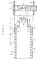
- a trailer of a photo filmstrip 2 is illustrated, as viewed for an emulsion surface.
- a trailer 34 of the photo filmstrip 2 has a retainer portion 3, which is formed narrower than the remaining portion of the photo filmstrip 2.
- the retainer portion 3 has a length B and a width W1.
- lateral edges 32 are cut along a first line 24 being perpendicular to the lateral edges 32.
- width W1 of the retainer portion 3 the trailer 34 is cut along second and third lines 25a and 25b being parallel to the lateral edges 32.
- the first line 24 has a position lying on a side of one of the perforations.
- the photo filmstrip 2 is symmetrically formed relative to a longitudinal line passing a center of the photo filmstrip 2.
- continuous photo film 8 for producing the photo filmstrip 2 is illustrated.
- the continuous photo film 8 is conveyed in the direction of the arrow at an amount as much as predetermined for a photo film size, the continuous photo film 8 is stopped and a cutter or trimmer is operated for forming a leader of a preceding photo filmstrip 2a and the trailer of the photo filmstrip 2 while eliminating a waste FW of the photo film.
- the first line 24 as edges of the trailer is located to lie on one of sides of the perforations 4 the less close to the end of the trailer 34.
- a pair of retaining holes 3a are formed by the cutter at the same time.
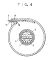
- the photo filmstrip 2 about the spool core 5 is contained in a cassette shell 10 having light shielding performance.
- the cassette shell 10 includes a metal thin body plate 11 rolled cylindrically, and two caps 12 fitted on distal ends of the roll of the body plate 11.
- a photo film passage port 13 is defined in the roll of the body plate 11.
- a light-trapping fabric 14 is disposed in the photo film passage port 13.
- the leader of the photo filmstrip 2 is protruded from the photo film passage port 13 at a predetermined length.
- the leader of the photo filmstrip 2 is manually picked and pulled as much as required in the loading.
- An end of the leader is fitted on a take-up spool of the camera. If a camera having an auto-loading mechanism is used, the leader end is placed near to the take-up spool in a manner determined structurally.
- a user may rotate the spool core 5 opposite to a direction of photo film winding, with incidental intention to draw out the leader as much as required. If the leader is drawn out longer than required, the spool core 5 can be rotated in the winding direction counterclockwise in Fig. 4 for the purpose of winding back a surplus portion of the leader. If the user is unaccustomed to the use of the photo film cassette, he or she is likely to rotate the spool core 5 opposite to the winding direction.
- a gap L is formed between the spool core 5 and an innermost one of the turns of the photo filmstrip 2.
- the spool core 5 is rotated further in the counterclockwise direction in Fig. 4, a portion of the photo filmstrip 2 protruded from the slot 6 receives application of force in a direction of orienting the emulsion surface convexly, opposite to the direction of winding of the photo filmstrip 2.
- a point D lying on the first line 24 is indicated in Fig. 5A. The portion at the point D receives push of an open edge of the slot 6, so that the photo filmstrip 2 receives strong force in the opposite rotational direction inside the gap L of Fig. 6.
- the portions at the first line 24 flex or bend as illustrated in Fig. 5B and absorb the force.
- the conventional photo filmstrip is broken only upon small reverse rotation of the spool core 5 with occurrence of the gap L of Fig. 6.
- the photo filmstrip 2 of the present invention is not broken even upon small reverse rotation of the spool core 5 with occurrence of the gap L. If the spool core 5 is rotated accidentally in the opposite rotational direction, the photo filmstrip 2 can be saved: upon discovering the accidental reverse rotation, the spool core 5 can be rotated in the winding direction.
- the photo filmstrip 2 is usable without breakage.
- corners Pa in Fig. 1 are cut away along fourth and fifth lines for gradual decrease of the width of the between the lateral edges 32 in a direction toward the first line 24.
- sixth and seventh lines Pb are formed with a slow curvature having a radius R1 for gradual increase of the width of the retainer portion 3 toward the first line 24.
- the slow curvature R1 is slower than that of a conventional photo filmstrip.
- a preferable radius R1 of the curvature of the sixth and seventh lines Pb is at least 5 mm.
- the corners Pa and the sixth and seventh lines Pb are formed at the same time as the retainer portion 3, upon the cutting operation of the photo filmstrip 2 from the continuous photo film 8. It is possible to form the sixth and seventh lines Pb upon the cutting operation of the photo filmstrip 2 from the continuous photo film 8, and later to cut to obtain the corners Pa.
- FIG. 7A illustrates another preferred embodiment of the present invention.
- a first line 27 is adapted to cut the photo filmstrip 2 from the continuous photo film 8, and, as edges of the trailer, is located to lie on one of sides of the perforations 4 the closer to the end of the trailer 34.
- t4 is an interval between a first one of the perforations 4 at the first line 27 and a second one of the perforations 4 succeeding to the first.
- a portion at a point G lying on the first line 27 is pushed on the open edge of the slot 6.
- a narrow portion 29 and a corner portion 30 formed by the cutting absorb the strong force of bending in the opposite rotational direction. There occurs no stress sufficient for breaking the photo filmstrip 2.
- the present invention is also applicable to a photo filmstrip in which a first line is located transverse to one of the perforations, namely located between two sides of one perforation perpendicular to lateral edges 32. This meets t ⁇ t1 ⁇ t + t3.
- the slot 6 is used for retention of the retainer portion 3 to the spool core 5.
- the present invention is also applicable to a cassette which does not have the slot 6 and in which the retainer portion 3 is attached to the spool core 5 in a different manner, for example with an adhesive tape.
Claims (16)
- Bande de pellicule photographique dans laquelle plusieurs perforations rectangulaires sont disposées le long de chaque bord latéral à intervalles réguliers (t), la bande de pellicule photographique étant enroulée sur une bobine sous forme d'un rouleau avec une extrémité arrière enroulée vers l'intérieur, la bande de pellicule photographique comprenant :
une partie (3) d'organe de retenue destinée à assurer la retenue sur la bobine, formée avec une largeur réduite (W1) comme une languette par découpe des bords latéraux de la partie arrière avec une forme en L le long d'une première, d'une seconde et d'une troisième ligne, la première ligne (24, 27) étant pratiquement perpendiculaire aux bords latéraux, la seconde et la troisième ligne (25a, 25b) étant pratiquement parallèles aux bords latéraux, la première ligne se trouvant sur l'une des perforations qui ont été positionnées avant la formation de la partie d'organe de retenue le long des bords latéraux. - Bande de pellicule photographique selon la revendication 1, dans laquelle la partie (3) d'organe de retenue est maintenue par l'introduction dans une fente formée dans la bobine afin qu'elle s'étende en direction axiale.
- Bande de pellicule photographique selon la revendication 2, dans laquelle chacune des perforations a un premier, un second, un troisième et un quatrième côté, le premier et le second côté étant pratiquement perpendiculaires aux bords latéraux, le troisième et le quatrième côté étant pratiquement parallèles aux bords latéraux, le premier côté étant plus proche de l'extrémité arrière que le second côté.
- Bande de pellicule photographique selon la revendication 3, dans laquelle la première ligne (27) se trouve du premier côté, et ladite perforation délimite une cavité.
- Bande de pellicule photographique selon la revendication 3, dans laquelle la première ligne (24) se trouve du second côté, et ladite perforation a été coupée.
- Bande de pellicule photographique selon la revendication 1 ou 5, dans laquelle la largeur (W1) de la partie d'organe de retenue (3) augmente vers la première ligne (24).
- Bande de pellicule photographique selon la revendication 5 ou 6, dans laquelle deux coins (Pa) sont délimités entre la première ligne (24) et les bords latéraux et sont découpés le long de la quatrième et de la cinquième ligne inclinées respectivement par rapport aux bords latéraux avec réduction de largeur de la partie arrière vers la première ligne.
- Bande de pellicule photographique selon la revendication 6 ou 7, dans laquelle la seconde ligne est raccordée à la première ligne (24) par une sixième ligne, la troisième ligne est raccordée à la première ligne par une septième ligne, et les sixième et septième lignes sont courbées avec un rayon R1, et R1 est tel que R1 ≥ 5 mm.
- Bande de pellicule photographique selon la revendication 2 ou 6, comprenant en outre au moins un trou de retenue formé dans la partie d'organe de retenue (3) et destiné à permettre l'insertion d'au moins une griffe de retenue disposée dans la fente.
- Bande de pellicule photographique selon la revendication 9, dans laquelle la fente a une première et une seconde paroi, et la griffe de retenue au moins dépasse de la première paroi vers la seconde paroi.
- Procédé de production d'une bande de pellicule photographique, cette bande de pellicule photographique ayant plusieurs perforations rectangulaires qui sont placées le long de chaque bord latéral à intervalles réguliers (t), la bande de pellicule photographique étant enroulée sur une bobine sous forme d'un rouleau avec une partie arrière enroulée vers l'intérieur, le procédé de production de la bande de pellicule photographique comprenant une étape qui comporte :
la découpe de la bande de pellicule photographique dans une pellicule photographique continue pour la formation de l'organe arrière avec une partie d'organe de retenue (3) ayant une largeur réduite (W1) en forme de languette, la partie d'organe de retenue étant formée par découpe des bords latéraux de la partie arrière avec une forme en L le long d'une première, d'une seconde et d'une troisième ligne (25a, 25b), la première ligne (24, 27) étant pratiquement perpendiculaire aux bords latéraux, la seconde et la troisième ligne étant pratiquement parallèles aux bords latéraux, la première ligne se trouvant sur l'une des perforations formées dans la pellicule photographique continue, le partie d'organe de retenue étant insérée dans une fente formée dans une bobine afin qu'elle soit retenue. - Procédé de production d'une bande de pellicule photographique selon la revendication 11, dans lequel la partie arrière et la partie d'organe de retenue (3) sont formées du côté aval de la bande de pellicule photographique dans la direction de traitement consécutif de la pellicule photographique continue.
- Procédé de production d'une bande de pellicule photographique selon la revendication 11, dans lequel chacune des perforations a des premier, second, troisième et quatrième côtés, et le premier et le second côté sont pratiquement perpendiculaires aux bords latéraux, le troisième et le quatrième côté sont pratiquement parallèles aux bords latéraux, et le premier côté est plus proche de la partie arrière que le second côté.
- Procédé de production d'une bande de pellicule photographique selon la revendication 13, dans lequel la première ligne (27) se trouve du premier côté et ladite perforation délimite une cavité.
- Procédé de production d'une bande de pellicule photographique selon la revendication 13, dans lequel la première ligne (24) se trouve du second côté, et ladite perforation a été découpée dans la bande de pellicule photographique.
- Procédé de production d'une bande de pellicule photographique selon la revendication 15, dans lequel deux coins (Pa) sont délimités entre la première ligne (24) et les bords latéraux et sont découpés le long de la quatrième et de la cinquième ligne qui sont inclinées par rapport aux bords latéraux avec une réduction de largeur de la partie arrière vers la première ligne, et
la largeur (W1) de la partie d'organe de retenue (3) augmente vers la première ligne, la seconde ligne est raccordée à la première ligne par une sixième ligne, la troisième ligne est raccordée à la première ligne par une septième ligne, la sixième et la septième ligne sont courbées avec un rayon R1, et le rayon R1 est tel que R1 ≥ 5 mm.
Applications Claiming Priority (3)
| Application Number | Priority Date | Filing Date | Title |
|---|---|---|---|
| JP11948/96 | 1996-01-26 | ||
| JP8011948A JPH09204020A (ja) | 1996-01-26 | 1996-01-26 | 写真フイルム |
| JP1194896 | 1996-01-26 |
Publications (2)
| Publication Number | Publication Date |
|---|---|
| EP0786693A1 EP0786693A1 (fr) | 1997-07-30 |
| EP0786693B1 true EP0786693B1 (fr) | 1999-09-22 |
Family
ID=11791869
Family Applications (1)
| Application Number | Title | Priority Date | Filing Date |
|---|---|---|---|
| EP97100977A Expired - Lifetime EP0786693B1 (fr) | 1996-01-26 | 1997-01-22 | Film photographique |
Country Status (4)
| Country | Link |
|---|---|
| US (1) | US5871169A (fr) |
| EP (1) | EP0786693B1 (fr) |
| JP (1) | JPH09204020A (fr) |
| DE (1) | DE69700534T2 (fr) |
Families Citing this family (2)
| Publication number | Priority date | Publication date | Assignee | Title |
|---|---|---|---|---|
| EP0892299B1 (fr) * | 1997-07-15 | 2004-10-06 | Fuji Photo Film Co., Ltd. | Film photographique en rouleau combiné avec une bobine réceptrice |
| US7322542B2 (en) * | 2005-05-13 | 2008-01-29 | Eastman Kodak Company | Automatic web winding system |
Family Cites Families (12)
| Publication number | Priority date | Publication date | Assignee | Title |
|---|---|---|---|---|
| DE728251C (de) * | 1940-10-18 | 1942-11-23 | Ig Farbenindustrie Ag | Filmspule mit vollem Spulenkern |
| US3021085A (en) * | 1959-03-09 | 1962-02-13 | Eastman Kodak Co | Web wind up hub |
| US3115417A (en) * | 1960-06-02 | 1963-12-24 | Joseph M Christensen | Daylight fluorescent tape structure |
| US4275855A (en) * | 1979-05-24 | 1981-06-30 | Nippon Kogaku K.K. | Film take-up spool |
| JPS57172322A (en) * | 1981-04-17 | 1982-10-23 | Canon Inc | Automatic film advancing device |
| US4735437A (en) * | 1986-07-09 | 1988-04-05 | Fattibene Paul A | Quick tear tractor feed computer paper |
| US4852821A (en) * | 1988-08-29 | 1989-08-01 | Eastman Kodak Company | Spool for web-shaped film |
| DE4002789C2 (de) * | 1989-01-31 | 2001-01-11 | Fuji Photo Film Co Ltd | Fotografische Filmpatrone |
| US5125630A (en) * | 1989-11-02 | 1992-06-30 | Eastman Kodak Company | Apparatus for inserting leading end of web during spooling of strips of web |
| EP0485957B1 (fr) * | 1990-11-13 | 1997-04-02 | Fuji Photo Film Co., Ltd. | Cassette à film photographique |
| JPH05341444A (ja) * | 1992-02-24 | 1993-12-24 | Fuji Photo Film Co Ltd | 写真フィルム用スプール |
| US5295635A (en) * | 1992-08-28 | 1994-03-22 | Eastman Kodak Company | Spool to film attachment |
-
1996
- 1996-01-26 JP JP8011948A patent/JPH09204020A/ja active Pending
-
1997
- 1997-01-22 EP EP97100977A patent/EP0786693B1/fr not_active Expired - Lifetime
- 1997-01-22 DE DE69700534T patent/DE69700534T2/de not_active Expired - Lifetime
- 1997-01-24 US US08/788,778 patent/US5871169A/en not_active Expired - Fee Related
Also Published As
| Publication number | Publication date |
|---|---|
| JPH09204020A (ja) | 1997-08-05 |
| US5871169A (en) | 1999-02-16 |
| EP0786693A1 (fr) | 1997-07-30 |
| DE69700534T2 (de) | 2000-03-23 |
| DE69700534D1 (de) | 1999-10-28 |
Similar Documents
| Publication | Publication Date | Title |
|---|---|---|
| US4834306A (en) | Film cassette | |
| EP0378170A2 (fr) | Cassette pour films | |
| US3361380A (en) | Spool for photographic film | |
| EP0228369B1 (fr) | Procede de tirage de bandes | |
| EP0786693B1 (fr) | Film photographique | |
| US5054710A (en) | Spool for film and lens units | |
| EP0095148A2 (fr) | Bobine de film photographique | |
| EP0426159B1 (fr) | Cassette de film à avancement automatique | |
| CA1191730A (fr) | Pellicule photographique | |
| JPS62223753A (ja) | フイルムカセツト | |
| US4986486A (en) | Spool with clip for attaching a web to the spool | |
| EP0557972A1 (fr) | Bobine de film photographique | |
| JP3658903B2 (ja) | 写真フィルム | |
| JPH06148808A (ja) | 写真用ロールフィルムのカートリッジ | |
| EP0053856B1 (fr) | Cassette pour tenir et distribuer un rouleau de matériau en bande | |
| US5435499A (en) | Photographic film cassette | |
| JP2823337B2 (ja) | 金属帯の巻取方法 | |
| EP0539855B1 (fr) | Procédé de fication d'une pellicule en bande à une bobine et une pellicule enroulée ainsi obtenue | |
| US5540400A (en) | Universal film thrusting cartridge and method | |
| EP0342372A2 (fr) | Bobine, cassette et méthode de fixation d'un film photographique | |
| JP3259618B2 (ja) | フィルム搬送用リーダ | |
| JPS6136996Y2 (fr) | ||
| JP3470251B2 (ja) | フィルム搬送用リーダ及び連結方法 | |
| JPH01251030A (ja) | フィルム巻取用スプール | |
| JPH0660852U (ja) | 写真フィルム用スプール |
Legal Events
| Date | Code | Title | Description |
|---|---|---|---|
| PUAI | Public reference made under article 153(3) epc to a published international application that has entered the european phase |
Free format text: ORIGINAL CODE: 0009012 |
|
| AK | Designated contracting states |
Kind code of ref document: A1 Designated state(s): DE FR GB NL |
|
| 17P | Request for examination filed |
Effective date: 19970903 |
|
| GRAG | Despatch of communication of intention to grant |
Free format text: ORIGINAL CODE: EPIDOS AGRA |
|
| 17Q | First examination report despatched |
Effective date: 19981016 |
|
| GRAG | Despatch of communication of intention to grant |
Free format text: ORIGINAL CODE: EPIDOS AGRA |
|
| GRAG | Despatch of communication of intention to grant |
Free format text: ORIGINAL CODE: EPIDOS AGRA |
|
| GRAH | Despatch of communication of intention to grant a patent |
Free format text: ORIGINAL CODE: EPIDOS IGRA |
|
| GRAH | Despatch of communication of intention to grant a patent |
Free format text: ORIGINAL CODE: EPIDOS IGRA |
|
| GRAA | (expected) grant |
Free format text: ORIGINAL CODE: 0009210 |
|
| AK | Designated contracting states |
Kind code of ref document: B1 Designated state(s): DE FR GB NL |
|
| PG25 | Lapsed in a contracting state [announced via postgrant information from national office to epo] |
Ref country code: NL Free format text: LAPSE BECAUSE OF FAILURE TO SUBMIT A TRANSLATION OF THE DESCRIPTION OR TO PAY THE FEE WITHIN THE PRESCRIBED TIME-LIMIT Effective date: 19990922 Ref country code: FR Free format text: LAPSE BECAUSE OF FAILURE TO SUBMIT A TRANSLATION OF THE DESCRIPTION OR TO PAY THE FEE WITHIN THE PRESCRIBED TIME-LIMIT Effective date: 19990922 |
|
| REF | Corresponds to: |
Ref document number: 69700534 Country of ref document: DE Date of ref document: 19991028 |
|
| EN | Fr: translation not filed | ||
| NLV1 | Nl: lapsed or annulled due to failure to fulfill the requirements of art. 29p and 29m of the patents act | ||
| PLBE | No opposition filed within time limit |
Free format text: ORIGINAL CODE: 0009261 |
|
| STAA | Information on the status of an ep patent application or granted ep patent |
Free format text: STATUS: NO OPPOSITION FILED WITHIN TIME LIMIT |
|
| 26N | No opposition filed | ||
| REG | Reference to a national code |
Ref country code: GB Ref legal event code: IF02 |
|
| REG | Reference to a national code |
Ref country code: GB Ref legal event code: 732E |
|
| PGFP | Annual fee paid to national office [announced via postgrant information from national office to epo] |
Ref country code: GB Payment date: 20100120 Year of fee payment: 14 Ref country code: DE Payment date: 20091231 Year of fee payment: 14 |
|
| GBPC | Gb: european patent ceased through non-payment of renewal fee |
Effective date: 20110122 |
|
| PG25 | Lapsed in a contracting state [announced via postgrant information from national office to epo] |
Ref country code: GB Free format text: LAPSE BECAUSE OF NON-PAYMENT OF DUE FEES Effective date: 20110122 |
|
| REG | Reference to a national code |
Ref country code: DE Ref legal event code: R119 Ref document number: 69700534 Country of ref document: DE Effective date: 20110802 |
|
| PG25 | Lapsed in a contracting state [announced via postgrant information from national office to epo] |
Ref country code: DE Free format text: LAPSE BECAUSE OF NON-PAYMENT OF DUE FEES Effective date: 20110802 |