EP0786693B1 - Photographic film - Google Patents
Photographic film Download PDFInfo
- Publication number
- EP0786693B1 EP0786693B1 EP97100977A EP97100977A EP0786693B1 EP 0786693 B1 EP0786693 B1 EP 0786693B1 EP 97100977 A EP97100977 A EP 97100977A EP 97100977 A EP97100977 A EP 97100977A EP 0786693 B1 EP0786693 B1 EP 0786693B1
- Authority
- EP
- European Patent Office
- Prior art keywords
- line
- photo filmstrip
- photo
- lateral edges
- filmstrip
- Prior art date
- Legal status (The legal status is an assumption and is not a legal conclusion. Google has not performed a legal analysis and makes no representation as to the accuracy of the status listed.)
- Expired - Lifetime
Links
Images


Classifications
-
- G—PHYSICS
- G03—PHOTOGRAPHY; CINEMATOGRAPHY; ANALOGOUS TECHNIQUES USING WAVES OTHER THAN OPTICAL WAVES; ELECTROGRAPHY; HOLOGRAPHY
- G03C—PHOTOSENSITIVE MATERIALS FOR PHOTOGRAPHIC PURPOSES; PHOTOGRAPHIC PROCESSES, e.g. CINE, X-RAY, COLOUR, STEREO-PHOTOGRAPHIC PROCESSES; AUXILIARY PROCESSES IN PHOTOGRAPHY
- G03C1/00—Photosensitive materials
- G03C1/76—Photosensitive materials characterised by the base or auxiliary layers
- G03C1/765—Photosensitive materials characterised by the base or auxiliary layers characterised by the shape of the base, e.g. arrangement of perforations, jags
Definitions
- the present invention relates to a photographic film. More particularly, the present invention relates to a photographic film which is wound about a spool and preferably contained in a photo film cassette.
- Photographic film of 135 type has two trains of perforations arranged along respective lateral edges and at a regular pitch, and contained in a cassette shell of a photo film cassette having light shielding capacity.
- a trailer of the photo film is connected to a spool in the cassette shell, and is contained in the cassette shell after winding the photo film in a roll form.
- a trailer of a photo filmstrip 102 is illustrated. Perforations 4 are arranged at a regular pitch P.
- a trailer of the photo filmstrip 102 has a retainer portion 103, which is narrower than the remaining portion of the photo filmstrip 102.
- the retainer portion 103 has a length A and a width W.
- To define the length A of the retainer portion 103 lateral edges are cut along a first line 120 being perpendicular to the lateral edges.
- the first line 120 has a position lying between the perforations 4.
- the trailer is cut along second and third lines 121a and 121b being parallel to the lateral edges.
- Two retaining holes 3a are formed in the retainer portion 103.
- the retainer portion 103 is inserted in a slot 6 in a spool core 5, retaining claws 7 inside the slot 6 are engaged with the retaining holes 3a.
- the trailer is connected to the spool core 5, which is rotated in orienting the emulsion surface toward the spool core 5.
- the photo filmstrip 102 is wound on the spool core 5 in a roll form between flanges 5a.
- continuous photo film 8 for producing the photo filmstrip 102 is illustrated.
- the continuous photo film 8 is conveyed in the direction of the arrow at an amount as much as predetermined, the continuous photo film 8 is stopped and a cutter or trimmer is operated for forming a leader of a preceding photo filmstrip 102a and the trailer of the photo filmstrip 102 of Fig. 8, while eliminating a waste of the photo film.
- a pair of retaining holes 3a are formed by the cutter at the same time.
- the first line 120 has a position between the perforations.
- the photo filmstrip 102 meets t2 ⁇ t, where t is an interval between the perforations 4, and t2 is an interval between the first line 120 and one of the perforations 4 the closest to the end of the trailer.
- a shape of the cutter for shaping both the trailer of the photo filmstrip 102 and the leader of the photo filmstrip 102a is determined by considering the position of the first line 120.
- the photo filmstrip 102 about the spool core 5 is contained in a cassette shell light-tightly (See Figs. 3 and 4). Initially the leader of the photo filmstrip 102 is protruded from a photo film passage port. To load a camera with the photo filmstrip 102, the leader is manually picked and pulled as much as required. An end of the leader is fitted on a take-up spool of the camera. If a camera having an auto-loading mechanism is used, the leader end is placed near to the take-up spool suitably.
- a user may rotate the spool core 5 opposite to a direction of photo film winding, with incidental intention to draw out the leader as much as required. If the leader is drawn out longer than required, the spool core 5 can be rotated in the winding direction for the purpose of winding back a surplus portion of the leader. If the user is unaccustomed to the use of the photo film cassette, he or she is likely to rotate the spool core 5 opposite to the winding direction. As the leader of the photo filmstrip 102 is in frictional contact with light-trapping fabric in the passage port, the roll of the photo filmstrip 102 becomes loosed inside the cassette about the spool core 5 being rotated. A gap L is formed between the spool core 5 and an innermost one of the turns of the photo filmstrip 102 (See Fig. 6).
- the spool core 5 is rotated further in the direction opposite to the direction of winding of the photo filmstrip 102.
- a portion of the photo filmstrip 102 protruded from the slot 6 is pressed by force in a direction of orienting the emulsion surface convexly.
- a point H lying on the first line 120 is indicated in Fig. 10A. The portion at the point H is pushed by an open edge of the slot 6, so that the photo filmstrip 102 receives strong force in the opposite rotational direction inside the gap L (See Fig. 6).
- the photo filmstrip 102 kept in the roll form has irresistible tendency of maintaining a curl in a longitudinal direction.
- the photo filmstrip 102 also has a curling tendency in a width direction like an archway.
- the portions at the first line 120 flex or bend as illustrated in Fig. 10B. Stress occurs in directions of the arrows in the drawing at the perforations 4.
- the photo filmstrip 102 is likely to break from a corner of one of the perforations 4 along the broken line indicated in the drawing, only upon small reverse rotation of the spool core 5 with occurrence of the gap L (See Fig. 6).
- Fig. 11 is a graph of a condition of breakage of the photo filmstrip 102 upon reverse winding of the photo filmstrip 102 having the above-described shape.
- a horizontal axis is determined to take the available frame number of the photo filmstrip 102, or the maximum number of frames photographable to the photo filmstrip 102.
- a right-hand vertical axis is determined to take bending force BF (in grams) applied to the innermost turn of the photo filmstrip 102 in the opposite rotational direction.
- a left-hand vertical axis is determined to take the gap L (in mm).
- a linear velocity of rotation for reverse winding of the photo filmstrip 102 is 500 mm/sec.
- the gap L decreased according to an increase of the available frame number, and that the bending force BF increases according to the increase of the available frame number. If the photo filmstrip 102 has the gap L being small due to smallness of the available frame number, it is difficult for the photo filmstrip 102 to bend back upon reverse rotation of the spool core 5, so that the bending force BF applied to the photo filmstrip 102 is great. The greatness of the bending force BF is remarkable when the photo filmstrip 102 has the available frame number as great as 31-33 frames. Approximately 20 % or more of the photo filmstrip 102 of this length is broken and becomes unusable. The bending force BF is much greater if the photo filmstrip 102 has the available frame number as great as 34-36 frames. Approximately 70 % or more of the photo filmstrip 102 of this length is broken.
- an object of the present invention is to provide a photographic film which is wound about a spool and contained in a photo film cassette, and is prevented from being broken away from the spool even upon inadvertent reverse rotation of the spool.
- a photo filmstrip has plural rectangular perforations are arranged along each of lateral edges and at a regular interval.
- the photo filmstrip is wound about a spool in a roll form with a trailer thereof wound inwards.
- the photo filmstrip has a retainer portion adapted to retention on the spool, formed at a smaller width like a tongue by cutting the lateral edges of the trailer in an L-shape along first, second and third lines.
- the first line being substantially perpendicular to the lateral edges.
- the second and third lines are substantially parallel to the lateral edges.
- the first line lies on one of the perforations having been arranged before forming the retainer portion along the lateral edges.
- the retainer portion is preferably retained in insertion into a slot formed in the spool to extend in an axial direction.
- each of said perforations has first, second, third and fourth sides, said first and second sides are substantially perpendicular to said lateral edges, said third and fourth sides are substantially parallel to said lateral edges, and said first side lies nearer to said trailer than said second side.
- Such a photo filmstrip preferably further comprises at least one retaining hole, formed in said retainer portion, for receiving insertion of at least one retaining claw disposed in said slot, and said slot preferably has first and second walls, and said at least one retaining claw projects over said first wall toward said second wall.
- two corners are defined between the first line and the lateral edges, and are cut down along fourth and fifth lines being inclined respectively with respect to the lateral edges with a decrease in a width of the trailer toward the first line.
- width of the retainer portion is increased toward the first line.
- the photographic film is reliably prevented from being broken away from the spool even upon inadvertent reverse rotation of the spool.
- a trailer of a photo filmstrip 2 is illustrated, as viewed for an emulsion surface.
- a trailer 34 of the photo filmstrip 2 has a retainer portion 3, which is formed narrower than the remaining portion of the photo filmstrip 2.
- the retainer portion 3 has a length B and a width W1.
- lateral edges 32 are cut along a first line 24 being perpendicular to the lateral edges 32.
- width W1 of the retainer portion 3 the trailer 34 is cut along second and third lines 25a and 25b being parallel to the lateral edges 32.
- the first line 24 has a position lying on a side of one of the perforations.
- the photo filmstrip 2 is symmetrically formed relative to a longitudinal line passing a center of the photo filmstrip 2.
- continuous photo film 8 for producing the photo filmstrip 2 is illustrated.
- the continuous photo film 8 is conveyed in the direction of the arrow at an amount as much as predetermined for a photo film size, the continuous photo film 8 is stopped and a cutter or trimmer is operated for forming a leader of a preceding photo filmstrip 2a and the trailer of the photo filmstrip 2 while eliminating a waste FW of the photo film.
- the first line 24 as edges of the trailer is located to lie on one of sides of the perforations 4 the less close to the end of the trailer 34.
- a pair of retaining holes 3a are formed by the cutter at the same time.
- the photo filmstrip 2 about the spool core 5 is contained in a cassette shell 10 having light shielding performance.
- the cassette shell 10 includes a metal thin body plate 11 rolled cylindrically, and two caps 12 fitted on distal ends of the roll of the body plate 11.
- a photo film passage port 13 is defined in the roll of the body plate 11.
- a light-trapping fabric 14 is disposed in the photo film passage port 13.
- the leader of the photo filmstrip 2 is protruded from the photo film passage port 13 at a predetermined length.
- the leader of the photo filmstrip 2 is manually picked and pulled as much as required in the loading.
- An end of the leader is fitted on a take-up spool of the camera. If a camera having an auto-loading mechanism is used, the leader end is placed near to the take-up spool in a manner determined structurally.
- a user may rotate the spool core 5 opposite to a direction of photo film winding, with incidental intention to draw out the leader as much as required. If the leader is drawn out longer than required, the spool core 5 can be rotated in the winding direction counterclockwise in Fig. 4 for the purpose of winding back a surplus portion of the leader. If the user is unaccustomed to the use of the photo film cassette, he or she is likely to rotate the spool core 5 opposite to the winding direction.
- a gap L is formed between the spool core 5 and an innermost one of the turns of the photo filmstrip 2.
- the spool core 5 is rotated further in the counterclockwise direction in Fig. 4, a portion of the photo filmstrip 2 protruded from the slot 6 receives application of force in a direction of orienting the emulsion surface convexly, opposite to the direction of winding of the photo filmstrip 2.
- a point D lying on the first line 24 is indicated in Fig. 5A. The portion at the point D receives push of an open edge of the slot 6, so that the photo filmstrip 2 receives strong force in the opposite rotational direction inside the gap L of Fig. 6.
- the portions at the first line 24 flex or bend as illustrated in Fig. 5B and absorb the force.
- the conventional photo filmstrip is broken only upon small reverse rotation of the spool core 5 with occurrence of the gap L of Fig. 6.
- the photo filmstrip 2 of the present invention is not broken even upon small reverse rotation of the spool core 5 with occurrence of the gap L. If the spool core 5 is rotated accidentally in the opposite rotational direction, the photo filmstrip 2 can be saved: upon discovering the accidental reverse rotation, the spool core 5 can be rotated in the winding direction.
- the photo filmstrip 2 is usable without breakage.
- corners Pa in Fig. 1 are cut away along fourth and fifth lines for gradual decrease of the width of the between the lateral edges 32 in a direction toward the first line 24.
- sixth and seventh lines Pb are formed with a slow curvature having a radius R1 for gradual increase of the width of the retainer portion 3 toward the first line 24.
- the slow curvature R1 is slower than that of a conventional photo filmstrip.
- a preferable radius R1 of the curvature of the sixth and seventh lines Pb is at least 5 mm.
- the corners Pa and the sixth and seventh lines Pb are formed at the same time as the retainer portion 3, upon the cutting operation of the photo filmstrip 2 from the continuous photo film 8. It is possible to form the sixth and seventh lines Pb upon the cutting operation of the photo filmstrip 2 from the continuous photo film 8, and later to cut to obtain the corners Pa.
- FIG. 7A illustrates another preferred embodiment of the present invention.
- a first line 27 is adapted to cut the photo filmstrip 2 from the continuous photo film 8, and, as edges of the trailer, is located to lie on one of sides of the perforations 4 the closer to the end of the trailer 34.
- t4 is an interval between a first one of the perforations 4 at the first line 27 and a second one of the perforations 4 succeeding to the first.
- a portion at a point G lying on the first line 27 is pushed on the open edge of the slot 6.
- a narrow portion 29 and a corner portion 30 formed by the cutting absorb the strong force of bending in the opposite rotational direction. There occurs no stress sufficient for breaking the photo filmstrip 2.
- the present invention is also applicable to a photo filmstrip in which a first line is located transverse to one of the perforations, namely located between two sides of one perforation perpendicular to lateral edges 32. This meets t ⁇ t1 ⁇ t + t3.
- the slot 6 is used for retention of the retainer portion 3 to the spool core 5.
- the present invention is also applicable to a cassette which does not have the slot 6 and in which the retainer portion 3 is attached to the spool core 5 in a different manner, for example with an adhesive tape.
Landscapes
- Chemical & Material Sciences (AREA)
- Engineering & Computer Science (AREA)
- Materials Engineering (AREA)
- Physics & Mathematics (AREA)
- General Physics & Mathematics (AREA)
- Details Of Cameras Including Film Mechanisms (AREA)
Description
- The present invention relates to a photographic film. More particularly, the present invention relates to a photographic film which is wound about a spool and preferably contained in a photo film cassette.
- Photographic film of 135 type has two trains of perforations arranged along respective lateral edges and at a regular pitch, and contained in a cassette shell of a photo film cassette having light shielding capacity. A trailer of the photo film is connected to a spool in the cassette shell, and is contained in the cassette shell after winding the photo film in a roll form.
- In Fig. 8, a trailer of a
photo filmstrip 102 is illustrated.Perforations 4 are arranged at a regular pitch P. A trailer of thephoto filmstrip 102 has aretainer portion 103, which is narrower than the remaining portion of thephoto filmstrip 102. Theretainer portion 103 has a length A and a width W. To define the length A of theretainer portion 103, lateral edges are cut along afirst line 120 being perpendicular to the lateral edges. Thefirst line 120 has a position lying between theperforations 4. To define the width W of theretainer portion 103, the trailer is cut along second andthird lines - Two
retaining holes 3a are formed in theretainer portion 103. When theretainer portion 103 is inserted in aslot 6 in aspool core 5, retainingclaws 7 inside theslot 6 are engaged with theretaining holes 3a. Then the trailer is connected to thespool core 5, which is rotated in orienting the emulsion surface toward thespool core 5. Thephoto filmstrip 102 is wound on thespool core 5 in a roll form betweenflanges 5a. - In Fig. 9,
continuous photo film 8 for producing thephoto filmstrip 102 is illustrated. When thecontinuous photo film 8 is conveyed in the direction of the arrow at an amount as much as predetermined, thecontinuous photo film 8 is stopped and a cutter or trimmer is operated for forming a leader of a precedingphoto filmstrip 102a and the trailer of thephoto filmstrip 102 of Fig. 8, while eliminating a waste of the photo film. A pair of retainingholes 3a are formed by the cutter at the same time. - In the
photo filmstrip 102, thefirst line 120 has a position between the perforations. In Fig. 8, thephoto filmstrip 102 meets t2 < t, where t is an interval between theperforations 4, and t2 is an interval between thefirst line 120 and one of theperforations 4 the closest to the end of the trailer. A shape of the cutter for shaping both the trailer of thephoto filmstrip 102 and the leader of thephoto filmstrip 102a is determined by considering the position of thefirst line 120. - The
photo filmstrip 102 about thespool core 5 is contained in a cassette shell light-tightly (See Figs. 3 and 4). Initially the leader of thephoto filmstrip 102 is protruded from a photo film passage port. To load a camera with thephoto filmstrip 102, the leader is manually picked and pulled as much as required. An end of the leader is fitted on a take-up spool of the camera. If a camera having an auto-loading mechanism is used, the leader end is placed near to the take-up spool suitably. - A user may rotate the
spool core 5 opposite to a direction of photo film winding, with incidental intention to draw out the leader as much as required. If the leader is drawn out longer than required, thespool core 5 can be rotated in the winding direction for the purpose of winding back a surplus portion of the leader. If the user is unaccustomed to the use of the photo film cassette, he or she is likely to rotate thespool core 5 opposite to the winding direction. As the leader of thephoto filmstrip 102 is in frictional contact with light-trapping fabric in the passage port, the roll of thephoto filmstrip 102 becomes loosed inside the cassette about thespool core 5 being rotated. A gap L is formed between thespool core 5 and an innermost one of the turns of the photo filmstrip 102 (See Fig. 6). - The
spool core 5 is rotated further in the direction opposite to the direction of winding of thephoto filmstrip 102. A portion of thephoto filmstrip 102 protruded from theslot 6 is pressed by force in a direction of orienting the emulsion surface convexly. A point H lying on thefirst line 120 is indicated in Fig. 10A. The portion at the point H is pushed by an open edge of theslot 6, so that thephoto filmstrip 102 receives strong force in the opposite rotational direction inside the gap L (See Fig. 6). - The
photo filmstrip 102 kept in the roll form has irresistible tendency of maintaining a curl in a longitudinal direction. Thephoto filmstrip 102 also has a curling tendency in a width direction like an archway. Upon application of the force in the opposite rotational direction against the curling tendency of the innermost turn of thephoto filmstrip 102, the portions at thefirst line 120 flex or bend as illustrated in Fig. 10B. Stress occurs in directions of the arrows in the drawing at theperforations 4. Thephoto filmstrip 102 is likely to break from a corner of one of theperforations 4 along the broken line indicated in the drawing, only upon small reverse rotation of thespool core 5 with occurrence of the gap L (See Fig. 6). - The gap L is unfavorable specially when small. As an outer shape of the cassette shell is unchanged, the gap L depends on the length of the
photo filmstrip 102. Fig. 11 is a graph of a condition of breakage of thephoto filmstrip 102 upon reverse winding of thephoto filmstrip 102 having the above-described shape. In the graph, a horizontal axis is determined to take the available frame number of thephoto filmstrip 102, or the maximum number of frames photographable to thephoto filmstrip 102. A right-hand vertical axis is determined to take bending force BF (in grams) applied to the innermost turn of thephoto filmstrip 102 in the opposite rotational direction. A left-hand vertical axis is determined to take the gap L (in mm). Thephoto filmstrip 102 has the interval t2 = 0.5 mm, and thickness of 142 µm. Specific features of thephoto filmstrip 102 are as follows: - Tear strength: 30 g/cm2 in the longitudinal direction; and 45 g/cm2 in the width direction;
- Modulus of elasticity: 590 kgf/mm2 in the longitudinal direction; and 420 kgf/mm2 in the width direction;
- Elongation: 36 % in the longitudinal direction; and 32 % in the width direction.
-
- A linear velocity of rotation for reverse winding of the
photo filmstrip 102 is 500 mm/sec. - It was observed in Fig. 11 that the gap L decreased according to an increase of the available frame number, and that the bending force BF increases according to the increase of the available frame number. If the
photo filmstrip 102 has the gap L being small due to smallness of the available frame number, it is difficult for thephoto filmstrip 102 to bend back upon reverse rotation of thespool core 5, so that the bending force BF applied to thephoto filmstrip 102 is great. The greatness of the bending force BF is remarkable when thephoto filmstrip 102 has the available frame number as great as 31-33 frames. Approximately 20 % or more of thephoto filmstrip 102 of this length is broken and becomes unusable. The bending force BF is much greater if thephoto filmstrip 102 has the available frame number as great as 34-36 frames. Approximately 70 % or more of thephoto filmstrip 102 of this length is broken. - Likeliness of breakage of the
photo filmstrip 102 upon reverse bend of thephoto filmstrip 102 increases according to the smallness of the gap L and thus a great length of thephoto filmstrip 102. This likeliness is more conspicuous under low temperature which heightens rigidity of a support material of thephoto filmstrip 102, or if the support material has characteristically high rigidity irrespective of the environment. Thephoto filmstrip 102 is disconnected from thespool core 5 to make it impossible to use the photo film cassette any longer, because thephoto filmstrip 102 cannot be developed in the photo film processor even after incidental success of taking exposures to thephoto filmstrip 102 in the camera. - In view of the foregoing problems, an object of the present invention is to provide a photographic film which is wound about a spool and contained in a photo film cassette, and is prevented from being broken away from the spool even upon inadvertent reverse rotation of the spool.
- In order to achieve the above and other objects and advantages of this invention, a photo filmstrip has plural rectangular perforations are arranged along each of lateral edges and at a regular interval. The photo filmstrip is wound about a spool in a roll form with a trailer thereof wound inwards. The photo filmstrip has a retainer portion adapted to retention on the spool, formed at a smaller width like a tongue by cutting the lateral edges of the trailer in an L-shape along first, second and third lines. The first line being substantially perpendicular to the lateral edges. The second and third lines are substantially parallel to the lateral edges. The first line lies on one of the perforations having been arranged before forming the retainer portion along the lateral edges.
- The retainer portion is preferably retained in insertion into a slot formed in the spool to extend in an axial direction.
- In this case it is preferred that each of said perforations has first, second, third and fourth sides, said first and second sides are substantially perpendicular to said lateral edges, said third and fourth sides are substantially parallel to said lateral edges, and said first side lies nearer to said trailer than said second side.
- Such a photo filmstrip preferably further comprises at least one retaining hole, formed in said retainer portion, for receiving insertion of at least one retaining claw disposed in said slot,
and
said slot preferably has first and second walls, and said at least one retaining claw projects over said first wall toward said second wall. - In a preferred embodiment, two corners are defined between the first line and the lateral edges, and are cut down along fourth and fifth lines being inclined respectively with respect to the lateral edges with a decrease in a width of the trailer toward the first line.
- Furthermore the width of the retainer portion is increased toward the first line.
- In accordance with the present invention, the photographic film is reliably prevented from being broken away from the spool even upon inadvertent reverse rotation of the spool.
- The above objects and advantages of the present invention will become more apparent from the following detailed description when read in connection with the accompanying drawings, in which:
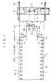
- Fig. 1 is a plan, partially cut away, illustrating a trailer of a photo filmstrip with a spool;
- Fig. 2 is a plan illustrating continuous photo film from which the trailer of the photo filmstrip is cut;
- Fig. 3 is a longitudinal section illustrating a photo film cassette;
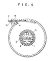
- Fig. 4 is a cross section illustrating the photo film cassette;
- Fig. 5A is a partial plan illustrating a portion of the photo filmstrip at a first line for cutting;
- Fig. 5B is a partial plan illustrating the portion at the first line being flexed or bent;
- Fig. 6 is a cross section illustrating the photo film cassette of which the spool is rotated in reverse inadvertently;
- Figs. 7A and 7B are partial plans illustrating another preferred photo filmstrip having the portion at a variant first line;
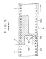
- Fig. 8 is a plan, partially cut away, illustrating a trailer of a photo filmstrip of the prior art with a spool;
- Fig. 9 is a plan illustrating continuous photo film from which the trailer of the photo filmstrip is cut according to the prior art;
- Fig. 10A is a partial plan illustrating a portion of the conventional photo filmstrip at a first line for cutting;
- Fig. 10B is a partial plan illustrating the portion at the first line being bent destructively according to the prior art; and
- Fig. 11 is a graph illustrating a condition of breakage of the conventional photo filmstrip upon reverse winding.
-
- In Fig. 1, a trailer of a
photo filmstrip 2 is illustrated, as viewed for an emulsion surface. Atrailer 34 of thephoto filmstrip 2 has aretainer portion 3, which is formed narrower than the remaining portion of thephoto filmstrip 2. Theretainer portion 3 has a length B and a width W1. To define the length B of theretainer portion 3, lateral edges 32 are cut along afirst line 24 being perpendicular to the lateral edges 32. To define the width W1 of theretainer portion 3, thetrailer 34 is cut along second andthird lines perforations 4 formed along the lateral edges 32 at a regular pitch P. - In the
photo filmstrip 2, thefirst line 24 has a position lying on a side of one of the perforations. In Fig. 1, thephoto filmstrip 2 meets t1 = t , where t is an interval between theperforations 4, and t1 is an interval between thefirst line 24 and one of theperforations 4 the closest to the end of thetrailer 34. - There are two retaining
holes 3a formed in theretainer portion 3. When theretainer portion 3 is inserted in aslot 6 in aspool core 5, retainingclaws 7 inside theslot 6 are engaged with the retainingholes 3a. Then thetrailer 34 is connected to thespool core 5, which is rotated in orienting the emulsion surface toward thespool core 5. Thephoto filmstrip 2 is wound on thespool core 5 in a roll form betweenflanges 5a. Details of thespool core 5 is described in the commonly assigned U.S. Patent No. 5,487,513. - The
photo filmstrip 2 is symmetrically formed relative to a longitudinal line passing a center of thephoto filmstrip 2. Dimensions of thephoto filmstrip 2 are as follows: t3 = 2 mm, t = 2.8 mm, t1 = 2.8 mm, B = 13 mm, W1 = 15 mm, W2 = 8 mm, and C = 10 mm, where t3 is a width of each of theperforations 4, B is the length of the second andthird lines retainer portion 3, W2 is an interval between centers of the retainingholes 3a, and C is a length of each segments of thefirst line 24. - In Fig. 2,
continuous photo film 8 for producing thephoto filmstrip 2 is illustrated. When thecontinuous photo film 8 is conveyed in the direction of the arrow at an amount as much as predetermined for a photo film size, thecontinuous photo film 8 is stopped and a cutter or trimmer is operated for forming a leader of a preceding photo filmstrip 2a and the trailer of thephoto filmstrip 2 while eliminating a waste FW of the photo film. Thefirst line 24 as edges of the trailer is located to lie on one of sides of theperforations 4 the less close to the end of thetrailer 34. A pair of retainingholes 3a are formed by the cutter at the same time. - In Figs. 3 and 4, the
photo filmstrip 2 about thespool core 5 is contained in acassette shell 10 having light shielding performance. Thecassette shell 10 includes a metalthin body plate 11 rolled cylindrically, and twocaps 12 fitted on distal ends of the roll of thebody plate 11. A photofilm passage port 13 is defined in the roll of thebody plate 11. A light-trappingfabric 14 is disposed in the photofilm passage port 13. - The operation of the photo film cassette is described now. Initially the leader of the
photo filmstrip 2 is protruded from the photofilm passage port 13 at a predetermined length. To load a camera with thephoto filmstrip 2, the leader of thephoto filmstrip 2 is manually picked and pulled as much as required in the loading. An end of the leader is fitted on a take-up spool of the camera. If a camera having an auto-loading mechanism is used, the leader end is placed near to the take-up spool in a manner determined structurally. - A user may rotate the
spool core 5 opposite to a direction of photo film winding, with incidental intention to draw out the leader as much as required. If the leader is drawn out longer than required, thespool core 5 can be rotated in the winding direction counterclockwise in Fig. 4 for the purpose of winding back a surplus portion of the leader. If the user is unaccustomed to the use of the photo film cassette, he or she is likely to rotate thespool core 5 opposite to the winding direction. - In Fig. 6, a gap L is formed between the
spool core 5 and an innermost one of the turns of thephoto filmstrip 2. Thespool core 5 is rotated further in the counterclockwise direction in Fig. 4, a portion of thephoto filmstrip 2 protruded from theslot 6 receives application of force in a direction of orienting the emulsion surface convexly, opposite to the direction of winding of thephoto filmstrip 2. A point D lying on thefirst line 24 is indicated in Fig. 5A. The portion at the point D receives push of an open edge of theslot 6, so that thephoto filmstrip 2 receives strong force in the opposite rotational direction inside the gap L of Fig. 6. - The
first line 24 and theperforations 4 are arranged to meet t1 = t , so that the one of theperforations 4 the closest to the end of thetrailer 34 is given high resistance to deformation. Upon application of the force in the opposite rotational direction against curling tendency of the innermost turn of thephoto filmstrip 2, the portions at thefirst line 24 flex or bend as illustrated in Fig. 5B and absorb the force. According to the prior art, the conventional photo filmstrip is broken only upon small reverse rotation of thespool core 5 with occurrence of the gap L of Fig. 6. However thephoto filmstrip 2 of the present invention is not broken even upon small reverse rotation of thespool core 5 with occurrence of the gap L. If thespool core 5 is rotated accidentally in the opposite rotational direction, thephoto filmstrip 2 can be saved: upon discovering the accidental reverse rotation, thespool core 5 can be rotated in the winding direction. Thephoto filmstrip 2 is usable without breakage. - It is also possible in the present invention that corners Pa in Fig. 1 are cut away along fourth and fifth lines for gradual decrease of the width of the between the
lateral edges 32 in a direction toward thefirst line 24. It is possible that sixth and seventh lines Pb are formed with a slow curvature having a radius R1 for gradual increase of the width of theretainer portion 3 toward thefirst line 24. The slow curvature R1 is slower than that of a conventional photo filmstrip. The curvatures of the corners Pa may be respectively formed according to a function y = x3 . A preferable radius R1 of the curvature of the sixth and seventh lines Pb is at least 5 mm. - It is to be noted that the corners Pa and the sixth and seventh lines Pb are formed at the same time as the
retainer portion 3, upon the cutting operation of thephoto filmstrip 2 from thecontinuous photo film 8. It is possible to form the sixth and seventh lines Pb upon the cutting operation of thephoto filmstrip 2 from thecontinuous photo film 8, and later to cut to obtain the corners Pa. - Fig. 7A illustrates another preferred embodiment of the present invention. A
first line 27 is adapted to cut thephoto filmstrip 2 from thecontinuous photo film 8, and, as edges of the trailer, is located to lie on one of sides of theperforations 4 the closer to the end of thetrailer 34. After cutting thefirst line 27, the photo filmstrip meets t4 = t , where t4 is an interval between a first one of theperforations 4 at thefirst line 27 and a second one of theperforations 4 succeeding to the first. When thespool core 5 is rotated opposite to the winding direction, a portion at a point G lying on thefirst line 27 is pushed on the open edge of theslot 6. In Fig. 7B, anarrow portion 29 and acorner portion 30 formed by the cutting absorb the strong force of bending in the opposite rotational direction. There occurs no stress sufficient for breaking thephoto filmstrip 2. - Of course the present invention is also applicable to a photo filmstrip in which a first line is located transverse to one of the perforations, namely located between two sides of one perforation perpendicular to lateral edges 32. This meets t < t1 < t + t3.
- In the above embodiments, the
slot 6 is used for retention of theretainer portion 3 to thespool core 5. The present invention is also applicable to a cassette which does not have theslot 6 and in which theretainer portion 3 is attached to thespool core 5 in a different manner, for example with an adhesive tape. - Although the present invention has been fully described by way of the preferred embodiments thereof with reference to the accompanying drawings, various changes and modifications will be apparent to those having skill in this field. Therefore, unless otherwise these changes and modifications depart from the scope of the present invention, they should be construed as included therein.
Claims (16)
- A photo filmstrip in which plural rectangular perforations are arranged along each of lateral edges and at a regular interval (t), said photo filmstrip being wound about a spool in a roll form with a trailer thereof wound inwards, said photo filmstrip comprising:
a retainer portion (3) adapted to retention on said spool, formed at a smaller width (W1) like a tongue by cutting said lateral edges of said trailer in an L-shape along first, second and third lines, said first line (24, 27) being substantially perpendicular to said lateral edges, said second and third lines (25a, 25b) being substantially parallel to said lateral edges, said first line lying on one of said perforations having been arranged before forming said retainer portion along said lateral edges. - A photo filmstrip as defined in claim 1, wherein said retainer portion (3) is retained in insertion into a slot formed in said spool to extend in an axial direction.
- A photo filmstrip as defined in claim 2, wherein each of said perforations has first, second, third and fourth sides, said first and second sides are substantially perpendicular to said lateral edges, said third and fourth sides are substantially parallel to said lateral edges, and said first side lies nearer to said trailer than said second side.
- A photo filmstrip as defined in claim 3, wherein said first line (27) lies on said first side, and said one of said perforations defines a recess.
- A photo filmstrip as defined in claim 3, wherein said first line (24) lies on said second side, and said one of said perforations has been cut away.
- A photo filmstrip as defined in claim 1 or 5, wherein said width (W1) of said retainer portion (3) is increased toward said first line (24).
- A photo filmstrip as defined in claim 5 or 6, wherein two corners (Pa) are defined between said first line (24) and said lateral edges, and are cut down along fourth and fifth lines being inclined respectively with respect to said lateral edges with a decrease in a width of said trailer toward said first line.
- A photo filmstrip as defined in claim 6 or 7, wherein said second line is connected to said first line (24) via a sixth line, said third line is connected to said first line via a seventh line, said sixth and seventh lines are curved at a radius R1, and R1 ≥ 5 mm.
- A photo filmstrip as defined in claim 2 or 6, further comprising at least one retaining hole, formed in said retainer portion (3), for receiving insertion of at least one retaining claw disposed in said slot.
- A photo filmstrip as defined in claim 9, wherein said slot has first and second walls, and said at least one retaining claw projects over said first wall toward said second wall.
- A method of producing a photo filmstrip, said photo filmstrip having plural rectangular perforations which are arranged along each of lateral edges and at a regular interval (t), said photo filmstrip being wound about a spool in a roll form with a trailer thereof wound inwards, said photo filmstrip producing method comprising a step of:
cutting said photo filmstrip away from a continuous photo film to provide said trailer with a retainer portion (3) at a smaller width (W1) like a tongue, said retainer portion being formed by cutting said lateral edges of said trailer in an L-shape along first, second and third lines (25a, 25b), said first line (24, 27) being substantially perpendicular to said lateral edges, said second and third lines being substantially parallel to said lateral edges, said first line lying on one of said perforations in said continuous photo film, said retainer portion being inserted into a slot in said spool for retention. - A photo filmstrip producing method as defined in claim 11,
wherein said trailer and said retainer portion (3) are formed on a downstream side of said photo filmstrip with respect to a direction of consecutively handling said continuous photo film. - A photo filmstrip producing method as defined in claim 11,
wherein each of said perforations has first, second, third and fourth sides, and first and second sides are substantially perpendicular to said lateral edges, said third and fourth sides are substantially parallel to said lateral edges, and said first side lies nearer to said trailer than said second side. - A photo filmstrip producing method as defined in claim 13,
wherein said first line (27) lies on said first side, and said one of said perforations defines a recess. - A photo filmstrip producing method as defined in claim 13,
wherein said first line (24) lies on said second side, and said one of said perforations has been cut away from said photo filmstrip. - A photo filmstrip producing method as defined in claim 15,wherein two corners (Pa) are defined between said first line (24) and said lateral edges, and are cut down along fourth and fifth lines being inclined respectively with respect to said lateral edges with a decrease in a width of said trailer toward said first line;said width (W1) of said retainer portion (3) is increased toward said first line, said second line is connected to said first line via a sixth line, said third line is connected to said first line via a seventh line, and sixth and seventh lines are curved at a radius R1, and R1 ≥ 5 mm.
Applications Claiming Priority (3)
| Application Number | Priority Date | Filing Date | Title |
|---|---|---|---|
| JP8011948A JPH09204020A (en) | 1996-01-26 | 1996-01-26 | Photographic film |
| JP1194896 | 1996-01-26 | ||
| JP11948/96 | 1996-01-26 |
Publications (2)
| Publication Number | Publication Date |
|---|---|
| EP0786693A1 EP0786693A1 (en) | 1997-07-30 |
| EP0786693B1 true EP0786693B1 (en) | 1999-09-22 |
Family
ID=11791869
Family Applications (1)
| Application Number | Title | Priority Date | Filing Date |
|---|---|---|---|
| EP97100977A Expired - Lifetime EP0786693B1 (en) | 1996-01-26 | 1997-01-22 | Photographic film |
Country Status (4)
| Country | Link |
|---|---|
| US (1) | US5871169A (en) |
| EP (1) | EP0786693B1 (en) |
| JP (1) | JPH09204020A (en) |
| DE (1) | DE69700534T2 (en) |
Families Citing this family (2)
| Publication number | Priority date | Publication date | Assignee | Title |
|---|---|---|---|---|
| EP0892299B1 (en) * | 1997-07-15 | 2004-10-06 | Fuji Photo Film Co., Ltd. | Roll photo film and take-up spool combined therewith |
| US7322542B2 (en) * | 2005-05-13 | 2008-01-29 | Eastman Kodak Company | Automatic web winding system |
Family Cites Families (12)
| Publication number | Priority date | Publication date | Assignee | Title |
|---|---|---|---|---|
| DE728251C (en) * | 1940-10-18 | 1942-11-23 | Ig Farbenindustrie Ag | Film reel with full core |
| US3021085A (en) * | 1959-03-09 | 1962-02-13 | Eastman Kodak Co | Web wind up hub |
| US3115417A (en) * | 1960-06-02 | 1963-12-24 | Joseph M Christensen | Daylight fluorescent tape structure |
| US4275855A (en) * | 1979-05-24 | 1981-06-30 | Nippon Kogaku K.K. | Film take-up spool |
| JPS57172322A (en) * | 1981-04-17 | 1982-10-23 | Canon Inc | Automatic film advancing device |
| US4735437A (en) * | 1986-07-09 | 1988-04-05 | Fattibene Paul A | Quick tear tractor feed computer paper |
| US4852821A (en) * | 1988-08-29 | 1989-08-01 | Eastman Kodak Company | Spool for web-shaped film |
| DE4002789C2 (en) * | 1989-01-31 | 2001-01-11 | Fuji Photo Film Co Ltd | Photographic film cartridge |
| US5125630A (en) * | 1989-11-02 | 1992-06-30 | Eastman Kodak Company | Apparatus for inserting leading end of web during spooling of strips of web |
| EP0485957B1 (en) * | 1990-11-13 | 1997-04-02 | Fuji Photo Film Co., Ltd. | A photographic film cassette |
| JPH05341444A (en) * | 1992-02-24 | 1993-12-24 | Fuji Photo Film Co Ltd | Spool for photographic film |
| US5295635A (en) * | 1992-08-28 | 1994-03-22 | Eastman Kodak Company | Spool to film attachment |
-
1996
- 1996-01-26 JP JP8011948A patent/JPH09204020A/en active Pending
-
1997
- 1997-01-22 DE DE69700534T patent/DE69700534T2/en not_active Expired - Lifetime
- 1997-01-22 EP EP97100977A patent/EP0786693B1/en not_active Expired - Lifetime
- 1997-01-24 US US08/788,778 patent/US5871169A/en not_active Expired - Fee Related
Also Published As
| Publication number | Publication date |
|---|---|
| EP0786693A1 (en) | 1997-07-30 |
| US5871169A (en) | 1999-02-16 |
| DE69700534T2 (en) | 2000-03-23 |
| DE69700534D1 (en) | 1999-10-28 |
| JPH09204020A (en) | 1997-08-05 |
Similar Documents
| Publication | Publication Date | Title |
|---|---|---|
| US4572460A (en) | Means for pulling tape from a reel | |
| EP0378170A2 (en) | Film cassette | |
| AU588246B2 (en) | Means for pulling tape from a reel | |
| EP0786693B1 (en) | Photographic film | |
| US5054710A (en) | Spool for film and lens units | |
| EP0095148A2 (en) | Spool for photographic film | |
| EP0426159B1 (en) | Self-advancing film cassette | |
| CA1191730A (en) | Photographic film assemblage | |
| JPS62223753A (en) | Film cassette | |
| US4986486A (en) | Spool with clip for attaching a web to the spool | |
| EP0557972A1 (en) | Photographic film spool | |
| JPH06148808A (en) | Photographic roll film cartridge | |
| EP0053856B1 (en) | Cassette for holding and dispensing a roll of web material | |
| US6033128A (en) | Rolled film backing paper with cinch tabs | |
| JP2823337B2 (en) | Winding method of metal band | |
| EP0539855B1 (en) | Method for attaching web to a spool and resulting spooled web | |
| US5540400A (en) | Universal film thrusting cartridge and method | |
| EP0342372A2 (en) | Spool, cartridge and method for fastening a photographic film | |
| JPS58120246A (en) | Roll film cartridge for camera | |
| JP3259618B2 (en) | Film transport reader | |
| JPS6136996Y2 (en) | ||
| JP3470251B2 (en) | Film transport reader and connection method | |
| JP3210768B2 (en) | Photo film wrapper | |
| EP0585749A2 (en) | Photographic film package | |
| JPH0660852U (en) | Spool for photographic film |
Legal Events
| Date | Code | Title | Description |
|---|---|---|---|
| PUAI | Public reference made under article 153(3) epc to a published international application that has entered the european phase |
Free format text: ORIGINAL CODE: 0009012 |
|
| AK | Designated contracting states |
Kind code of ref document: A1 Designated state(s): DE FR GB NL |
|
| 17P | Request for examination filed |
Effective date: 19970903 |
|
| GRAG | Despatch of communication of intention to grant |
Free format text: ORIGINAL CODE: EPIDOS AGRA |
|
| 17Q | First examination report despatched |
Effective date: 19981016 |
|
| GRAG | Despatch of communication of intention to grant |
Free format text: ORIGINAL CODE: EPIDOS AGRA |
|
| GRAG | Despatch of communication of intention to grant |
Free format text: ORIGINAL CODE: EPIDOS AGRA |
|
| GRAH | Despatch of communication of intention to grant a patent |
Free format text: ORIGINAL CODE: EPIDOS IGRA |
|
| GRAH | Despatch of communication of intention to grant a patent |
Free format text: ORIGINAL CODE: EPIDOS IGRA |
|
| GRAA | (expected) grant |
Free format text: ORIGINAL CODE: 0009210 |
|
| AK | Designated contracting states |
Kind code of ref document: B1 Designated state(s): DE FR GB NL |
|
| PG25 | Lapsed in a contracting state [announced via postgrant information from national office to epo] |
Ref country code: NL Free format text: LAPSE BECAUSE OF FAILURE TO SUBMIT A TRANSLATION OF THE DESCRIPTION OR TO PAY THE FEE WITHIN THE PRESCRIBED TIME-LIMIT Effective date: 19990922 Ref country code: FR Free format text: LAPSE BECAUSE OF FAILURE TO SUBMIT A TRANSLATION OF THE DESCRIPTION OR TO PAY THE FEE WITHIN THE PRESCRIBED TIME-LIMIT Effective date: 19990922 |
|
| REF | Corresponds to: |
Ref document number: 69700534 Country of ref document: DE Date of ref document: 19991028 |
|
| EN | Fr: translation not filed | ||
| NLV1 | Nl: lapsed or annulled due to failure to fulfill the requirements of art. 29p and 29m of the patents act | ||
| PLBE | No opposition filed within time limit |
Free format text: ORIGINAL CODE: 0009261 |
|
| STAA | Information on the status of an ep patent application or granted ep patent |
Free format text: STATUS: NO OPPOSITION FILED WITHIN TIME LIMIT |
|
| 26N | No opposition filed | ||
| REG | Reference to a national code |
Ref country code: GB Ref legal event code: IF02 |
|
| REG | Reference to a national code |
Ref country code: GB Ref legal event code: 732E |
|
| PGFP | Annual fee paid to national office [announced via postgrant information from national office to epo] |
Ref country code: GB Payment date: 20100120 Year of fee payment: 14 Ref country code: DE Payment date: 20091231 Year of fee payment: 14 |
|
| GBPC | Gb: european patent ceased through non-payment of renewal fee |
Effective date: 20110122 |
|
| PG25 | Lapsed in a contracting state [announced via postgrant information from national office to epo] |
Ref country code: GB Free format text: LAPSE BECAUSE OF NON-PAYMENT OF DUE FEES Effective date: 20110122 |
|
| REG | Reference to a national code |
Ref country code: DE Ref legal event code: R119 Ref document number: 69700534 Country of ref document: DE Effective date: 20110802 |
|
| PG25 | Lapsed in a contracting state [announced via postgrant information from national office to epo] |
Ref country code: DE Free format text: LAPSE BECAUSE OF NON-PAYMENT OF DUE FEES Effective date: 20110802 |