EP0786231A2 - Hydraulische Verbindungsvorrichtung für einen auf zwei unterschiedlichen Höhen positionierbaren Geschirrkorb - Google Patents
Hydraulische Verbindungsvorrichtung für einen auf zwei unterschiedlichen Höhen positionierbaren Geschirrkorb Download PDFInfo
- Publication number
- EP0786231A2 EP0786231A2 EP97830020A EP97830020A EP0786231A2 EP 0786231 A2 EP0786231 A2 EP 0786231A2 EP 97830020 A EP97830020 A EP 97830020A EP 97830020 A EP97830020 A EP 97830020A EP 0786231 A2 EP0786231 A2 EP 0786231A2
- Authority
- EP
- European Patent Office
- Prior art keywords
- inlet
- outlet
- chamber
- rack
- shutter
- Prior art date
- Legal status (The legal status is an assumption and is not a legal conclusion. Google has not performed a legal analysis and makes no representation as to the accuracy of the status listed.)
- Granted
Links
Images

Classifications
-
- A—HUMAN NECESSITIES
- A47—FURNITURE; DOMESTIC ARTICLES OR APPLIANCES; COFFEE MILLS; SPICE MILLS; SUCTION CLEANERS IN GENERAL
- A47L—DOMESTIC WASHING OR CLEANING; SUCTION CLEANERS IN GENERAL
- A47L15/00—Washing or rinsing machines for crockery or tableware
- A47L15/42—Details
- A47L15/50—Racks ; Baskets
- A47L15/508—Hydraulic connections for racks
-
- A—HUMAN NECESSITIES
- A47—FURNITURE; DOMESTIC ARTICLES OR APPLIANCES; COFFEE MILLS; SPICE MILLS; SUCTION CLEANERS IN GENERAL
- A47L—DOMESTIC WASHING OR CLEANING; SUCTION CLEANERS IN GENERAL
- A47L15/00—Washing or rinsing machines for crockery or tableware
- A47L15/14—Washing or rinsing machines for crockery or tableware with stationary crockery baskets and spraying devices within the cleaning chamber
- A47L15/18—Washing or rinsing machines for crockery or tableware with stationary crockery baskets and spraying devices within the cleaning chamber with movably-mounted spraying devices
- A47L15/22—Rotary spraying devices
- A47L15/23—Rotary spraying devices moved by means of the sprays
Definitions
- the present invention relates to dishwashers having the upper rack which can be positioned at two different heights, and in particular to a hydraulic connection device for said type of rack.
- a first solution is having a double outlet at the end of the supply pipe extending from the pump to the upper sprinkler, and keeping closed the outlet not in use according to the rack position.
- This can be achieved by providing on each outlet of the supply pipe a shutter which remains closed if said outlet is not in use, e.g. by means of an internal spring.
- an axial pin projecting from the feed duct of the upper rack sprinkler is inserted into an outlet, said pin causes the opening of the corresponding shutter by overcoming the spring resistance.
- the sprinkler feed duct may carry a pair of end shutters integral therewith, one above and one below. In this way, when an outlet is connected to the feed duct the other outlet is closed by the corresponding upper or lower shutter by pushing the rack upto the rear wall of the tank.
- Both these devices have a first drawback of greater dimensions and manufacturing complexity due to the need of providing a double outlet in the rear wall of the tank.
- a second drawback is the greater flow resistance caused by the presence of the second outlet not in use, where there is a stagnation and/or a recirculation of the water arriving at the top of the supply pipe.
- Another drawback of the internal spring shutter is that the spring is critical for a correct working thereof without leaks from the outlet not in use, whereby the device will be ineffective if the spring moves around or bends.
- the rack-carried shutters there is no effective tightness if the rack is not pushed well back to the rear wall, which can also occur due to the vibrations during the dishwasher operation.
- a second solution is forming a single outlet in the tank, as in conventional dishwashers, and providing the end of the sprinkler feed duct with a wide water-collecting cap.
- Said cap is high enough to enclose the outlet of the supply pipe in both the possible rack positions, and the tightness is achieved by having the cap abut against the rear wall of the tank.
- this solution has the drawback of a significant flow resistance caused by the recirculation of water within the wide cap prior to the entrance into the feed duct. Furthermore, also in this case there is the problem of the tightness depending from the correct positioning of the rack.
- the object of the present invention is to provide a hydraulic connection device for the upper rack suitable to overcome the abovementioned drawbacks of prior art devices.
- a first fundamental advantage of the device according to the present invention is its structural simplicity, which assures a cheap manufacturing and a reliable working.
- a second advantage of the present device stems from the fact that the tightness is assured by the pressure of the water flow itself, even if the rack is not perfectly pushed backwards along its guides.
- Still another advantage of the present device is the little flow resistance achieved by placing the shutter out of the main water flow.
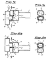
- the first embodiment essentially consists of an upper sprinkler feed duct 1 provided at the rear end with an enlarged chamber 2 divided into an upper inlet 3 and a lower inlet 3', which are identical and separate.
- These inlets 3, 3' can be alternately closed by a vane shutter 4 which rotates within chamber 2 around a horizontal pivot 5 located on the division wall between the two inlets, in correspondence with the axis of duct 1.
- Inlets 3, 3' are sized and shaped so as to fit externally on outlet 7 of the supply pipe 8, which projects from the rear wall 9 of the washing tank. The tightness between outlet 7 and inlet 3 or 3' is assured by a gasket 10.
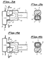
- the second embodiment illustrated in figs.3a, 3b, 4a and 4b is different from the previous embodiment only in the mechanism for closing the inlet not in use.
- the rotating vane 4 is replaced by a ball 11 which slides within chamber 2' along a guide rim 12 until it closes one of the inlets 3, 3' which are properly shaped with a circular seat.
- Chamber 2' is longer than chamber 2 in order to allow a smooth motion of ball 11 between the two closing positions.
- the closing of the lower inlet 3' is made easier by gravity, which tends to pull down vane 4 or ball 11 from the upper position to the lower position.
- the second embodiment illustrated in figs.5 and 6 is similar to the first embodiment but it includes two vane shutters 4' and 4" for the upper inlet 3 and the lower inlet 3', respectively. Furthermore, the enlarged chamber 2" is not centered with respect to the axis of the feed duct 1 but it extends upwards, whereby duct 1 is aligned with the lower inlet 3'.
- the outlet 7 of the supply pipe 8 may also be provided with tapered rims 13 which facilitate the entrance into inlet 3, 3' and open the vane shutters 4', 4". However, the presence of rims 13 is not strictly necessary in that vanes 4', 4" open anyway due to the action of the water under pressure and they close by gravity, since they are pivoted along their upper edge.
Landscapes
- Washing And Drying Of Tableware (AREA)
Applications Claiming Priority (2)
| Application Number | Priority Date | Filing Date | Title |
|---|---|---|---|
| ITMI960150 | 1996-01-29 | ||
| IT96MI000150A IT1282096B1 (it) | 1996-01-29 | 1996-01-29 | Dispositivo di collegamento idraulico per cestello di lavastoviglie posizionabile a due altezze diverse |
Publications (3)
| Publication Number | Publication Date |
|---|---|
| EP0786231A2 true EP0786231A2 (de) | 1997-07-30 |
| EP0786231A3 EP0786231A3 (de) | 1997-10-08 |
| EP0786231B1 EP0786231B1 (de) | 2000-03-29 |
Family
ID=11373056
Family Applications (1)
| Application Number | Title | Priority Date | Filing Date |
|---|---|---|---|
| EP97830020A Expired - Lifetime EP0786231B1 (de) | 1996-01-29 | 1997-01-28 | Hydraulische Verbindungsvorrichtung für einen auf zwei unterschiedlichen Höhen positionierbaren Geschirrkorb |
Country Status (4)
| Country | Link |
|---|---|
| EP (1) | EP0786231B1 (de) |
| DE (1) | DE69701535T2 (de) |
| ES (1) | ES2144837T3 (de) |
| IT (1) | IT1282096B1 (de) |
Cited By (30)
| Publication number | Priority date | Publication date | Assignee | Title |
|---|---|---|---|---|
| EP0829221A3 (de) * | 1996-09-11 | 1998-08-12 | Merloni Elettrodomestici S.p.A. | Geschirrspülmaschine mit verbessertem Hydraulikkreislauf |
| EP0864291A1 (de) * | 1997-02-25 | 1998-09-16 | SMEG S.p.A. | Hydraulische Verbindungsvorrichtung für einen auf zwei unterschiedliche Höhen positionierbaren Geschirrkorb |
| EP0872208A1 (de) * | 1997-03-18 | 1998-10-21 | SMEG S.p.A. | Hydraulische Verbindungsvorrichtung für einen auf zwei unterschiedliche Höhen positionierbaren Geschirrkorb |
| EP0918482B1 (de) * | 1996-07-17 | 2004-10-27 | Arcelik S.A. | Lösbare hydraulische verbindung oder flussigkeitsverteilungsventil für haushaltgeschirrspülmaschine |
| WO2008137818A1 (en) * | 2007-05-04 | 2008-11-13 | Electrolux Home Products, Inc. | Water delivery system for multi-position spray arm of a dishwasher |
| WO2010149343A1 (en) * | 2009-06-23 | 2010-12-29 | Electrolux Home Products Corporation N.V. | Dishwasher, especially domestic dishwasher |
| US8561624B2 (en) * | 2007-08-31 | 2013-10-22 | Bsh Bosch Und Siemens Hausgeraete Gmbh | Hydraulic coupling of a vertically adjustable dish basket of a dishwasher |
| WO2015003646A1 (zh) * | 2013-07-10 | 2015-01-15 | 佛山市顺德区美的洗涤电器制造有限公司 | 喷臂水路连接装置和具有其的洗碗机 |
| US10524634B2 (en) | 2017-09-29 | 2020-01-07 | Midea Group Co., Ltd. | Dishwasher with combined liquid and air sprayers |
| US10531781B2 (en) | 2017-09-29 | 2020-01-14 | Midea Group Co., Ltd. | Dishwasher with discretely directable tubular spray elements |
| US10631708B2 (en) | 2018-09-14 | 2020-04-28 | Midea Group Co., Ltd. | Dishwasher with docking arrangement for elevation-adjustable rack |
| US10765291B2 (en) | 2018-09-14 | 2020-09-08 | Midea Group Co., Ltd. | Dishwasher with check valve in rotatable docking port |
| US11000176B2 (en) | 2018-09-14 | 2021-05-11 | Midea Group Co., Ltd. | Dishwasher with rotatable diverter valve |
| US11026559B2 (en) | 2019-09-30 | 2021-06-08 | Midea Group Co., Ltd. | Dishwasher with image-based fluid condition sensing |
| US11045066B2 (en) | 2019-03-11 | 2021-06-29 | Midea Group Co., Ltd. | Dishwasher with keyed coupling to rack-mounted conduit |
| US11071440B2 (en) | 2018-09-14 | 2021-07-27 | Midea Group Co., Ltd. | Dishwasher with rack-mounted conduit return mechanism |
| US11185209B2 (en) | 2019-11-20 | 2021-11-30 | Midea Group Co., Ltd. | Dishwasher steam generator |
| US11191416B2 (en) | 2019-09-30 | 2021-12-07 | Midea Group Co., Ltd. | Dishwasher with image-based position sensor |
| US11202550B2 (en) | 2019-11-20 | 2021-12-21 | Midea Group Co., Ltd. | Dishwasher thermal imaging system |
| US11259681B2 (en) | 2019-09-30 | 2022-03-01 | Midea Group Co., Ltd | Dishwasher with image-based diagnostics |
| US11399690B2 (en) | 2019-09-30 | 2022-08-02 | Midea Group Co., Ltd. | Dishwasher with cam-based position sensor |
| US11412912B2 (en) | 2020-09-21 | 2022-08-16 | Midea Group Co., Ltd. | Dishwasher with tubular spray element slip ring alignment |
| US11464389B2 (en) | 2019-09-30 | 2022-10-11 | Midea Group Co., Ltd. | Dishwasher with image-based detergent sensing |
| US11484180B2 (en) | 2020-11-11 | 2022-11-01 | Midea Group Co., Ltd. | Dishwasher with tubular spray element including multiple selectable spray patterns |
| US11484183B2 (en) | 2019-09-30 | 2022-11-01 | Midea Group Co., Ltd. | Dishwasher with image-based object sensing |
| US11497374B2 (en) | 2020-02-19 | 2022-11-15 | Midea Group Co., Ltd. | Dishwasher with wall-mounted rotatable conduit |
| US11826001B2 (en) | 2022-02-15 | 2023-11-28 | Midea Group Co., Ltd. | Dishwasher with tubular spray element including elongated metal tube and retaining tab for mounting support member thereto |
| US12245735B2 (en) | 2022-02-25 | 2025-03-11 | Midea Group Co., Ltd. | Dishwasher including tubular spray element with intermediate support and/or fluid inlet |
| US12290225B2 (en) | 2017-09-29 | 2025-05-06 | Midea Group Co., Ltd. | Dishwasher with walking tubular spray element |
| US12329341B2 (en) | 2023-06-28 | 2025-06-17 | Midea Group Co., Ltd. | Dishwasher with rack-mounted tubular spray element assembly |
Family Cites Families (5)
| Publication number | Priority date | Publication date | Assignee | Title |
|---|---|---|---|---|
| DE2355271A1 (de) * | 1973-11-06 | 1975-05-07 | Licentia Gmbh | Geschirrspuelmaschine |
| SE444884B (sv) * | 1980-03-11 | 1986-05-20 | Electrolux Ab | Hushallsdiskmaskin |
| SE442703B (sv) * | 1981-11-24 | 1986-01-27 | Electrolux Ab | Kopplingsanordning for ett i en diskmaskin anordnat spolsystem |
| IT1234696B (it) * | 1989-06-06 | 1992-05-26 | Zanussi A Spa Industrie | Lavastoviglie con cesto estraibile regolabile in altezza. |
| DE4137227C2 (de) * | 1991-11-13 | 1999-12-16 | Aeg Hausgeraete Gmbh | Haushalt-Geschirrspülmaschine mit höhenverstellbarem Oberkorb |
-
1996
- 1996-01-29 IT IT96MI000150A patent/IT1282096B1/it active IP Right Grant
-
1997
- 1997-01-28 DE DE69701535T patent/DE69701535T2/de not_active Expired - Fee Related
- 1997-01-28 ES ES97830020T patent/ES2144837T3/es not_active Expired - Lifetime
- 1997-01-28 EP EP97830020A patent/EP0786231B1/de not_active Expired - Lifetime
Cited By (43)
| Publication number | Priority date | Publication date | Assignee | Title |
|---|---|---|---|---|
| EP0918482B1 (de) * | 1996-07-17 | 2004-10-27 | Arcelik S.A. | Lösbare hydraulische verbindung oder flussigkeitsverteilungsventil für haushaltgeschirrspülmaschine |
| EP0829221A3 (de) * | 1996-09-11 | 1998-08-12 | Merloni Elettrodomestici S.p.A. | Geschirrspülmaschine mit verbessertem Hydraulikkreislauf |
| EP0864291A1 (de) * | 1997-02-25 | 1998-09-16 | SMEG S.p.A. | Hydraulische Verbindungsvorrichtung für einen auf zwei unterschiedliche Höhen positionierbaren Geschirrkorb |
| EP0872208A1 (de) * | 1997-03-18 | 1998-10-21 | SMEG S.p.A. | Hydraulische Verbindungsvorrichtung für einen auf zwei unterschiedliche Höhen positionierbaren Geschirrkorb |
| WO2008137818A1 (en) * | 2007-05-04 | 2008-11-13 | Electrolux Home Products, Inc. | Water delivery system for multi-position spray arm of a dishwasher |
| US8561624B2 (en) * | 2007-08-31 | 2013-10-22 | Bsh Bosch Und Siemens Hausgeraete Gmbh | Hydraulic coupling of a vertically adjustable dish basket of a dishwasher |
| AU2010265067B2 (en) * | 2009-06-23 | 2016-06-16 | Electrolux Home Products Corporation N.V. | Dishwasher, especially domestic dishwasher |
| CN102458214A (zh) * | 2009-06-23 | 2012-05-16 | 伊莱克斯家用产品股份有限公司 | 洗碟机、特别地家用洗碟机 |
| CN102458214B (zh) * | 2009-06-23 | 2014-09-10 | 伊莱克斯家用产品股份有限公司 | 洗碟机、特别地家用洗碟机 |
| WO2010149343A1 (en) * | 2009-06-23 | 2010-12-29 | Electrolux Home Products Corporation N.V. | Dishwasher, especially domestic dishwasher |
| WO2015003646A1 (zh) * | 2013-07-10 | 2015-01-15 | 佛山市顺德区美的洗涤电器制造有限公司 | 喷臂水路连接装置和具有其的洗碗机 |
| US12290225B2 (en) | 2017-09-29 | 2025-05-06 | Midea Group Co., Ltd. | Dishwasher with walking tubular spray element |
| US10531781B2 (en) | 2017-09-29 | 2020-01-14 | Midea Group Co., Ltd. | Dishwasher with discretely directable tubular spray elements |
| US10524634B2 (en) | 2017-09-29 | 2020-01-07 | Midea Group Co., Ltd. | Dishwasher with combined liquid and air sprayers |
| US11058279B2 (en) | 2017-09-29 | 2021-07-13 | Midea Group Co., Ltd. | Dishwasher with discretely directable tubular spray elements |
| US11800963B2 (en) | 2017-09-29 | 2023-10-31 | Midea Group Co., Ltd. | Dishwasher with discretely directable tubular spray elements |
| US10631708B2 (en) | 2018-09-14 | 2020-04-28 | Midea Group Co., Ltd. | Dishwasher with docking arrangement for elevation-adjustable rack |
| US10765291B2 (en) | 2018-09-14 | 2020-09-08 | Midea Group Co., Ltd. | Dishwasher with check valve in rotatable docking port |
| US11000176B2 (en) | 2018-09-14 | 2021-05-11 | Midea Group Co., Ltd. | Dishwasher with rotatable diverter valve |
| US11071440B2 (en) | 2018-09-14 | 2021-07-27 | Midea Group Co., Ltd. | Dishwasher with rack-mounted conduit return mechanism |
| US12268347B2 (en) | 2018-09-14 | 2025-04-08 | Midea Group Co., Ltd. | Dishwasher with rotatable diverter valve |
| US11045066B2 (en) | 2019-03-11 | 2021-06-29 | Midea Group Co., Ltd. | Dishwasher with keyed coupling to rack-mounted conduit |
| US11766160B2 (en) | 2019-09-30 | 2023-09-26 | Midea Group Co., Ltd. | Dishwasher with image-based position sensor |
| US11877711B2 (en) | 2019-09-30 | 2024-01-23 | Midea Group Co., Ltd. | Dishwasher with image-based detergent sensing |
| US11399690B2 (en) | 2019-09-30 | 2022-08-02 | Midea Group Co., Ltd. | Dishwasher with cam-based position sensor |
| US11026559B2 (en) | 2019-09-30 | 2021-06-08 | Midea Group Co., Ltd. | Dishwasher with image-based fluid condition sensing |
| US11464389B2 (en) | 2019-09-30 | 2022-10-11 | Midea Group Co., Ltd. | Dishwasher with image-based detergent sensing |
| US12251066B2 (en) | 2019-09-30 | 2025-03-18 | Midea Group Co., Ltd. | Dishwasher with image-based diagnostics |
| US11484183B2 (en) | 2019-09-30 | 2022-11-01 | Midea Group Co., Ltd. | Dishwasher with image-based object sensing |
| US12042111B2 (en) | 2019-09-30 | 2024-07-23 | Midea Group Co., Ltd. | Dishwasher with cam-based position sensor |
| US11896182B2 (en) | 2019-09-30 | 2024-02-13 | Midea Group Co., Ltd. | Dishwasher with image-based object sensing |
| US11191416B2 (en) | 2019-09-30 | 2021-12-07 | Midea Group Co., Ltd. | Dishwasher with image-based position sensor |
| US11889966B2 (en) | 2019-09-30 | 2024-02-06 | Midea Group Co., Ltd. | Dishwasher with image-based object sensing |
| US11259681B2 (en) | 2019-09-30 | 2022-03-01 | Midea Group Co., Ltd | Dishwasher with image-based diagnostics |
| US11864705B2 (en) | 2019-11-20 | 2024-01-09 | Midea Group Co., Ltd. | Dishwasher thermal imaging system |
| US11202550B2 (en) | 2019-11-20 | 2021-12-21 | Midea Group Co., Ltd. | Dishwasher thermal imaging system |
| US11185209B2 (en) | 2019-11-20 | 2021-11-30 | Midea Group Co., Ltd. | Dishwasher steam generator |
| US11497374B2 (en) | 2020-02-19 | 2022-11-15 | Midea Group Co., Ltd. | Dishwasher with wall-mounted rotatable conduit |
| US11412912B2 (en) | 2020-09-21 | 2022-08-16 | Midea Group Co., Ltd. | Dishwasher with tubular spray element slip ring alignment |
| US11484180B2 (en) | 2020-11-11 | 2022-11-01 | Midea Group Co., Ltd. | Dishwasher with tubular spray element including multiple selectable spray patterns |
| US11826001B2 (en) | 2022-02-15 | 2023-11-28 | Midea Group Co., Ltd. | Dishwasher with tubular spray element including elongated metal tube and retaining tab for mounting support member thereto |
| US12245735B2 (en) | 2022-02-25 | 2025-03-11 | Midea Group Co., Ltd. | Dishwasher including tubular spray element with intermediate support and/or fluid inlet |
| US12329341B2 (en) | 2023-06-28 | 2025-06-17 | Midea Group Co., Ltd. | Dishwasher with rack-mounted tubular spray element assembly |
Also Published As
| Publication number | Publication date |
|---|---|
| ES2144837T3 (es) | 2000-06-16 |
| DE69701535D1 (de) | 2000-05-04 |
| IT1282096B1 (it) | 1998-03-12 |
| EP0786231A3 (de) | 1997-10-08 |
| EP0786231B1 (de) | 2000-03-29 |
| ITMI960150A1 (it) | 1997-07-29 |
| DE69701535T2 (de) | 2000-08-24 |
| ITMI960150A0 (de) | 1996-01-29 |
Similar Documents
| Publication | Publication Date | Title |
|---|---|---|
| EP0786231A2 (de) | Hydraulische Verbindungsvorrichtung für einen auf zwei unterschiedlichen Höhen positionierbaren Geschirrkorb | |
| EP0864291A1 (de) | Hydraulische Verbindungsvorrichtung für einen auf zwei unterschiedliche Höhen positionierbaren Geschirrkorb | |
| AU2018201977B2 (en) | Pump and dishwasher comprising the same | |
| ES2269751T3 (es) | Maquina lavavajillas con brazos de aspersion y una bomba de circulacion. | |
| US5131821A (en) | Aquarium pump with reversible and adjustable flows | |
| EP0872208B1 (de) | Hydraulische Verbindungsvorrichtung für einen auf zwei unterschiedliche Höhen positionierbaren Geschirrkorb | |
| EP0766945B1 (de) | Vorrichtung zum Waschen der Spülbehälterdecke einer Geschirrspülmaschine | |
| CN208443027U (zh) | 空调器室内机及具有其的空调器 | |
| IE46328B1 (en) | A valve unit for a liquid flow sensing device | |
| EP0829221A2 (de) | Geschirrspülmaschine mit verbessertem Hydraulikkreislauf | |
| US3578016A (en) | Antisiphon fluid inlet means | |
| KR200203368Y1 (ko) | 욕실환풍기의 역풍방지댐퍼 | |
| CN216984848U (zh) | 一种用于清洗机的呼吸器及清洗机 | |
| US3575004A (en) | Siphon tube control device and system | |
| CN114403771B (zh) | 用于清洗机的干燥组件及清洗机 | |
| KR20210012741A (ko) | 에어 벤트 그릴 | |
| CN212452947U (zh) | 一种马桶冲水装置的水流切换机构 | |
| CN110353489B (zh) | 一种带水盒组件的烹饪电器 | |
| CN220327422U (zh) | 一种清洗机 | |
| CN223548280U (zh) | 一种洗烘一体机进水结构 | |
| CN218761490U (zh) | 一种新型角阀 | |
| CN216535219U (zh) | 一种用于清洗机的排水结构及清洗机 | |
| CN215032040U (zh) | 抽风通道装置和清洗设备 | |
| CN214760555U (zh) | 一种用于烹饪设备的水路结构及电蒸箱 | |
| CN102116386A (zh) | 溢流阻断安全阀 |
Legal Events
| Date | Code | Title | Description |
|---|---|---|---|
| PUAI | Public reference made under article 153(3) epc to a published international application that has entered the european phase |
Free format text: ORIGINAL CODE: 0009012 |
|
| AK | Designated contracting states |
Kind code of ref document: A2 Designated state(s): DE ES FR GB IT SE |
|
| PUAL | Search report despatched |
Free format text: ORIGINAL CODE: 0009013 |
|
| AK | Designated contracting states |
Kind code of ref document: A3 Designated state(s): DE ES FR GB IT SE |
|
| 17P | Request for examination filed |
Effective date: 19980327 |
|
| GRAG | Despatch of communication of intention to grant |
Free format text: ORIGINAL CODE: EPIDOS AGRA |
|
| 17Q | First examination report despatched |
Effective date: 19990525 |
|
| GRAG | Despatch of communication of intention to grant |
Free format text: ORIGINAL CODE: EPIDOS AGRA |
|
| GRAH | Despatch of communication of intention to grant a patent |
Free format text: ORIGINAL CODE: EPIDOS IGRA |
|
| ITF | It: translation for a ep patent filed | ||
| GRAH | Despatch of communication of intention to grant a patent |
Free format text: ORIGINAL CODE: EPIDOS IGRA |
|
| GRAA | (expected) grant |
Free format text: ORIGINAL CODE: 0009210 |
|
| AK | Designated contracting states |
Kind code of ref document: B1 Designated state(s): DE ES FR GB IT SE |
|
| REF | Corresponds to: |
Ref document number: 69701535 Country of ref document: DE Date of ref document: 20000504 |
|
| REG | Reference to a national code |
Ref country code: ES Ref legal event code: FG2A Ref document number: 2144837 Country of ref document: ES Kind code of ref document: T3 |
|
| ET | Fr: translation filed | ||
| PLBE | No opposition filed within time limit |
Free format text: ORIGINAL CODE: 0009261 |
|
| STAA | Information on the status of an ep patent application or granted ep patent |
Free format text: STATUS: NO OPPOSITION FILED WITHIN TIME LIMIT |
|
| 26N | No opposition filed | ||
| REG | Reference to a national code |
Ref country code: GB Ref legal event code: IF02 |
|
| PGFP | Annual fee paid to national office [announced via postgrant information from national office to epo] |
Ref country code: IT Payment date: 20060131 Year of fee payment: 10 |
|
| PGFP | Annual fee paid to national office [announced via postgrant information from national office to epo] |
Ref country code: DE Payment date: 20070110 Year of fee payment: 11 |
|
| PGFP | Annual fee paid to national office [announced via postgrant information from national office to epo] |
Ref country code: SE Payment date: 20070111 Year of fee payment: 11 |
|
| PGFP | Annual fee paid to national office [announced via postgrant information from national office to epo] |
Ref country code: GB Payment date: 20070119 Year of fee payment: 11 |
|
| PGFP | Annual fee paid to national office [announced via postgrant information from national office to epo] |
Ref country code: ES Payment date: 20070130 Year of fee payment: 11 |
|
| PGFP | Annual fee paid to national office [announced via postgrant information from national office to epo] |
Ref country code: FR Payment date: 20070111 Year of fee payment: 11 |
|
| EUG | Se: european patent has lapsed | ||
| GBPC | Gb: european patent ceased through non-payment of renewal fee |
Effective date: 20080128 |
|
| PG25 | Lapsed in a contracting state [announced via postgrant information from national office to epo] |
Ref country code: DE Free format text: LAPSE BECAUSE OF NON-PAYMENT OF DUE FEES Effective date: 20080801 |
|
| REG | Reference to a national code |
Ref country code: FR Ref legal event code: ST Effective date: 20081029 |
|
| PG25 | Lapsed in a contracting state [announced via postgrant information from national office to epo] |
Ref country code: GB Free format text: LAPSE BECAUSE OF NON-PAYMENT OF DUE FEES Effective date: 20080128 |
|
| PG25 | Lapsed in a contracting state [announced via postgrant information from national office to epo] |
Ref country code: SE Free format text: LAPSE BECAUSE OF NON-PAYMENT OF DUE FEES Effective date: 20080129 |
|
| REG | Reference to a national code |
Ref country code: ES Ref legal event code: FD2A Effective date: 20080129 |
|
| PG25 | Lapsed in a contracting state [announced via postgrant information from national office to epo] |
Ref country code: FR Free format text: LAPSE BECAUSE OF NON-PAYMENT OF DUE FEES Effective date: 20080131 |
|
| PG25 | Lapsed in a contracting state [announced via postgrant information from national office to epo] |
Ref country code: ES Free format text: LAPSE BECAUSE OF NON-PAYMENT OF DUE FEES Effective date: 20080129 |
|
| PG25 | Lapsed in a contracting state [announced via postgrant information from national office to epo] |
Ref country code: IT Free format text: LAPSE BECAUSE OF NON-PAYMENT OF DUE FEES Effective date: 20070128 |