EP0786027B1 - Aiguilleteuse double frappe - Google Patents
Aiguilleteuse double frappe Download PDFInfo
- Publication number
- EP0786027B1 EP0786027B1 EP95934186A EP95934186A EP0786027B1 EP 0786027 B1 EP0786027 B1 EP 0786027B1 EP 95934186 A EP95934186 A EP 95934186A EP 95934186 A EP95934186 A EP 95934186A EP 0786027 B1 EP0786027 B1 EP 0786027B1
- Authority
- EP
- European Patent Office
- Prior art keywords
- needle loom
- loom according
- supports
- path
- needle
- Prior art date
- Legal status (The legal status is an assumption and is not a legal conclusion. Google has not performed a legal analysis and makes no representation as to the accuracy of the status listed.)
- Expired - Lifetime
Links
- 238000006073 displacement reaction Methods 0.000 claims 2
- 238000000034 method Methods 0.000 claims 1
- 238000000605 extraction Methods 0.000 abstract description 2
- 238000004519 manufacturing process Methods 0.000 abstract 1
- 125000006850 spacer group Chemical group 0.000 description 11
- 230000007246 mechanism Effects 0.000 description 6
- 230000035515 penetration Effects 0.000 description 4
- 230000002441 reversible effect Effects 0.000 description 4
- 240000008042 Zea mays Species 0.000 description 3
- 239000000835 fiber Substances 0.000 description 3
- 210000000056 organ Anatomy 0.000 description 2
- XLYOFNOQVPJJNP-UHFFFAOYSA-N water Substances O XLYOFNOQVPJJNP-UHFFFAOYSA-N 0.000 description 2
- 230000000712 assembly Effects 0.000 description 1
- 238000000429 assembly Methods 0.000 description 1
- 239000003673 groundwater Substances 0.000 description 1
- 230000010363 phase shift Effects 0.000 description 1
- 230000001360 synchronised effect Effects 0.000 description 1
- 230000001131 transforming effect Effects 0.000 description 1
Images
Classifications
-
- D—TEXTILES; PAPER
- D04—BRAIDING; LACE-MAKING; KNITTING; TRIMMINGS; NON-WOVEN FABRICS
- D04H—MAKING TEXTILE FABRICS, e.g. FROM FIBRES OR FILAMENTARY MATERIAL; FABRICS MADE BY SUCH PROCESSES OR APPARATUS, e.g. FELTS, NON-WOVEN FABRICS; COTTON-WOOL; WADDING ; NON-WOVEN FABRICS FROM STAPLE FIBRES, FILAMENTS OR YARNS, BONDED WITH AT LEAST ONE WEB-LIKE MATERIAL DURING THEIR CONSOLIDATION
- D04H18/00—Needling machines
- D04H18/02—Needling machines with needles
Definitions
- the present invention relates to a needling machine double tap.
- a needling machine is a machine in which we scroll a sheet of fibers, from for example a lapper spreader, while a board with many parallel needles is operated back and forth, so that the hands enter the water table and come out at a rate ranging from a few hundred to about two thousand blows per minute. This operation has for result of consolidating the tablecloth by interlacing the fibers that compose it.
- double impact needling machine we mean a needling machine comprising at least two planks needles each located opposite one of the faces the path of the tablecloth, so as to perform the needling operation from both sides of the tablecloth.
- the purpose of the present invention is to achieve a double impact needle that is less costly to carry out and the synchronization between needle boards is better, thanks to a shorter mechanical connection between the two boards, especially for needlepunchers for small and medium tablecloth width.
- the double needling machine strikes comprising a frame, means for guiding the minus one tablecloth along a scroll path, two supports each located opposite a respective face of the scroll path and intended to support each a needle board, means for guiding each support moving in a strike direction transverse to the faces of the scroll path, means for driving said supports back and forth according to the strike direction with between them a relative movement during the needling operation, is characterized in that the drive means back and forth are grouped next to a first face of the journey facing a first of the two supports, and in that it is provided between the means back and forth drive and the second support a mechanical connection which extends laterally relatively to said journey.
- all the means of training are common to the two needle boards from the source motor and at least up to the means of training in back and forth, which are grouped next to a same side of the journey. It is therefore particularly simple to establish by means of drive in go and comes, for example from the crank type, everything desired phase shift between the two needle boards, and this with very reduced mechanical clearances.
- the crank ways can just understand two cranks secured to each other. The realization is therefore considerably simplified. The synchronization is ensured in a much more direct between the two needle boards.
- the needling structure is less solicited only in known realizations where there are a rod-crank assembly on each side of the path of the tablecloth.
- the invention is applicable to connect the two supports independently of each other by means back and forth training while giving each plank one movement coordinated with respect to the other board.
- independently is meant that both board supports are not directly attached one to the other.
- coordinated movement we mean everything definite synchronized movement, including lack of movement relative between the two boards.
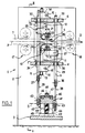
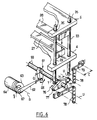
- the needling machine comprises a frame 1 essentially consisting of two side walls 2, vertical and parallel connected to each other by three spacers flat, parallel and horizontal, namely a lower spacer 3, a middle spacer 4 and a upper spacer 6.
- a needling path is defined in a plane horizontal P and in a direction D for the sheet 7 to needling, between a needling table 8 arranged horizontally under said path and a plate upper or “stripper" 9 arranged parallel to the table 8 at a certain distance above it.
- Table 8 is rigidly supported by the spacer median 4 by means of an adjustment means height 11.
- the stripper is rigidly supported by the upper spacer 6 by means height adjustment 12.
- each height adjustment means 11, 12 comprises two screw jacks 13 oriented vertically and whose nuts (not shown), each rotatably mounted in a housing 14, are actuated by a worm common 16.
- the sheet of fibers 7 is driven in scrolling the along the needling path by a device introduction 17 and an extraction device 18, each diagrammed by a pair of rotating cylinders in opposite directions and between which the web passes.
- the needling machine also includes a lower hands 19 located under table 8 and a upper needle board 21 located above the stripper 9.
- Each board 19, 21 includes a large number of needles 22 and 23 respectively oriented transverse to the plane P with their point directed towards the sheet 7 when the boards 19, 21 are in the withdrawal position shown in Figures 1 and 2.
- the needle boards 19, 21 are animated each of a back and forth movement according to a needling direction A perpendicular to the plane P, between the withdrawal position shown in Figures 1 and 2 to a position of penetration into the sheet 7 through openings or perforations 24 and 26 of the table 8 and stripper 9 respectively.
- each board needle 19, 21 is fixed to a support 27 and respectively 28.
- the lower support 27 is fixed rigidly with two sliding columns 29 (see also figure 3) mounted vertically, laterally from on either side of the path for groundwater 7.
- the upper support 28 is fixed to two vertical sliding columns 33 located laterally on either side of the path for water table 7.
- Each column 29 or 33 is guided in vertical sliding in a sliding bearing 34 through the spacer median 4 and 35 through the upper spacer 6.
- a beam 36 rigidly connects the columns 29 to each other by their lower end.
- columns 33 associated with the upper plate 21 are connected rigidly to each other by their ends lower, by means of a beam 37.
- the beams 36 and 37 are located between the lower spacer 3 and the middle spacer 4 and extend parallel to the path width for the tablecloth 7.
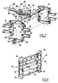
- In the middle of each beam 36, 37 is articulated at one end of a respective connecting rod 38, 39 extending downward from of the beam.
- the connecting rods 38, 39 are articulated by their other each end at a respective crank 41, 42 produced in the form of a crank pin or journal 43 formed in an eccentric position on a free end of a respective shaft 44 rotatably supported in a bearing respective 46.
- the axes of articulation of the two ends of the two connecting rods 38, 39 are parallel to the direction D of scrolling of the web 7, which allows the connecting rods 38 and 39 to oscillate in the Q and R planes respectively.
- the two cranks 41, 42 have an axis of rotation common S parallel to the direction D of travel of the tablecloth 7.
- the two cranks 41, 42 are integral with each other and with a pulley common drive 47 on which a toothed belt 48 connecting with a driving pulley 53 ( Figure 2) mounted for example on the shaft of an engine electric 51.
- the pulley 47 is located axially between the two trees 44, halfway between the planes Q and A.
- the housings 49 in which the bearings are mounted 46 are fixed on the upper face of the spacer lower 3.
- the two pins 43 are angularly offset by 180 ° around the S axis of the cranks 41 and 42, so that the needle boards 19 and 21 have one by relation to each other relative movement as they are both at the same time in withdrawal position as shown in Figures 1 and 2, then after a 180 ° rotation of the cranks, both at the same time time in penetration position as shown in figure 3.
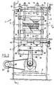
- the two cranks 41, 42 are always coaxial along the axis S, but they are free to rotate one with respect to the other, each with its own pulley 47 on which circulates a respective belt 48 or 148.
- the belt 48 is directly connected to the motor shaft 51.
- the other belt 148 rotates the crank 41 with a pulley 153 which is the same diameter as the pulley 53 mounted on the motor shaft 51.
- the pulley 153 is connected to the motor shaft 51 via of a couple of pinions 54 which reverse the direction of the rotation without changing the speed.
- cranks 41 and 42 turn in direction reverse each other.
- the two pins 43 are offset by 180 ° one relative to each other around the S axis whenever their center passes in the vertical plane containing the axis S, so as to fulfill the conditions of simultaneous strike operation.
- each pair of columns 29, 33 located on the same side of the web path a reversing pinion movement 56 mounted in rotation along an axis T parallel to the width of the tablecloth.
- Each sprocket 56 meshes in two diametrically opposite positions with two racks 57, 58 formed on a certain length of columns 29 and 33 respectively of the pair considered, from their lower end.
- the two pinions 56 are rigidly connected to each other by a shaft 59 supported in rotation along the axis T relative to the frame of the needling machine.
- the shaft 59 rigidly carries a lever 61 at mid-distance between the gables 56.
- a connecting rod 62 has one end hinged to the lever 61 and another end hinged to a crank 63 driven in continuous rotation by an electric motor 64.
- the radius of gyration G of the articulated end 66 of the connecting rod 62 around the axis T is larger than the radius of gyration "g" from its other end 67 around of the S axis of the crank 63. So the rotation continuous crank 63 produces a movement of and comes angularly from lever 61 and consequently from sprockets 56. This results in a back and forth movement longitudinal of columns 29 and 33 in the direction of hit. The movement of columns 29 is always opposite to that of columns 33, as symbolized by the arrows F1 and F2.
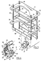
- each motion reversing gear 56 is replaced by a lever 76 fixed in the middle to the shaft 59 and whose two opposite ends 77 are each articulated at one end of a link 78.
- the other end of each link 78 is hinged to the movable end of a respective compensating arm 79 whose fixed end is articulated to the frame of the needling machine.
- the center distance E of each arm 79 is equal to the distance H between each axis of articulation of the lever 77 and its axis of rotation T.
- each link is articulated along an axis U to one respective columns 29 and 33.
- the arrangement is such that halfway back and forth, the two links 78 are substantially vertical, while the lever 76 and the arms 79 are substantially horizontal. From each link 78, the associated arm 79 extends in direction opposite to lever 76.
- This structure fully articulated not only ensures the back and forth drive from columns 29 and 33, but also almost perfect vertical guidance for U axes. This can be used to remove the bearings 34 or the bearings 35.
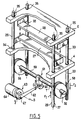
- a first difference is that the 83 back and forth drive mechanism for columns 29 and 33 is located above the scroll plane of the tablecloth to be needled, and no longer underneath.
- a second difference independent of the first, lies in the modified structure of the mechanism 83 to rotate the shaft 59 back and forth driving the reversing levers 76 now located in the upper position.
- Mechanism 83 includes a transformer movement 161 having one end shaped as a clevis 162 articulated to the shaft 59 along a perpendicular axis 163 to the axis of rotation T of the shaft 59.
- the motion transforming organ 161 is articulated to a motor shaft 164 along an axis 166 which is perpendicular and eccentric to the axis 167 of the motor shaft 164.
- the axis of rotation 167 of the shaft 164 intersects the hinge pin 163 and the axis T of the tree 59.
- the three axes T, 163 and 167 are concurrent at a point of intersection W.
- this drive mechanism in back and forth 83 is as follows: when the motor shaft 164 is in continuous rotation, the transformer movement 161 describes a C1 cone and this produced for the shaft 59 an angular back and forth having for amplitude the angle at the top of the cone C1.
- the mechanism 83 comprises two means of adjusting the angular travel of the shaft 59.
- the first means of adjustment makes it possible to move the motor shaft 164 along its own axis 167 as illustrated by the double arrow 168.
- the organ motion transformer 161 is produced in two parts one of which is a socket 169 hinged to the tree 164 along the axis 166, and the other is a tree 171 bearing the yoke 162 and sliding freely in the socket 169 along an axis 172 which is oblique to to axis 167 of tree 164.
- the bush 169 slides on the shaft 171 and this varies the angle at vertex of the cone described by the transformer movement 161.
- the member 161 can come to describe the cone C2 having a plus wide angle at the top than the C1 cone.
- a second adjustment means makes it possible to adjust the orientation of the motor shaft 164 around the axis of rotation T of the shaft 59, as is illustrated by arrows 173. So for a race given angularity of the shaft 59 and therefore for a stroke given needle boards, you can select the height position of the needles when they are in position of maximum penetration and respectively in position of maximum withdrawal relative to the web to to refer.
- the lower ends of the columns 29 and 33, opposite tree 59, are also each articulated with the middle of a link 88 one end of which is articulated to a compensating arm 89 and the other end is hinged at one end respectively of a reversing lever 86.
- the mounting of the reversing lever 86, connecting rods 88 and arms compensator 89 is substantially symmetrical to that of the reversing lever 76 of links 78 and arms compensators 79, with respect to a horizontal plane.
- Each reversing arm 86 is supported at its center in a bearing 174 which should preferably be supported elastically because the kinematic study shows that the bearing 174 undergoes vertical movements of the order of a millimeter.
- the embodiment of Figure 7 has the advantage completely remove the sliding guides (other that those who only experience relative movement when adjusting the machine).
- Reversing wheels 56 no longer drive columns 29 and 33 in opposite movements but each cooperate with an endless toothed belt 91 also bypassing upper reverse wheels 96. Between the wheels 56 and 96 each belt 91 has two vertical sections 93 and 99 movable vertically in opposite directions to each other. Supports 27 and 28 of needle boards are attached to sections 99 and the other to sections 93 of the two toothed belts 93.
- connection between the crank means and the needle board located opposite the other side of the tablecloth may not only go through one side of the scroll path of the ply 7.
- the means of guide cross the plane of travel of the web.
- crank set underneath of each pair of columns 29, 33 both crank assemblies being driven by belts notched from a common engine.
- crank pins can of course be replaced by eccentric bores receiving pins attached to the connecting rods.
Landscapes
- Engineering & Computer Science (AREA)
- Textile Engineering (AREA)
- Nonwoven Fabrics (AREA)
- Looms (AREA)
- Measurement Of The Respiration, Hearing Ability, Form, And Blood Characteristics Of Living Organisms (AREA)
- Infusion, Injection, And Reservoir Apparatuses (AREA)
Applications Claiming Priority (3)
| Application Number | Priority Date | Filing Date | Title |
|---|---|---|---|
| FR9412064 | 1994-10-10 | ||
| FR9412064A FR2725458A1 (fr) | 1994-10-10 | 1994-10-10 | Aiguilleteuse double frappe |
| PCT/FR1995/001311 WO1996011294A1 (fr) | 1994-10-10 | 1995-10-09 | Aiguilleteuse double frappe |
Publications (2)
| Publication Number | Publication Date |
|---|---|
| EP0786027A1 EP0786027A1 (fr) | 1997-07-30 |
| EP0786027B1 true EP0786027B1 (fr) | 1998-09-23 |
Family
ID=9467712
Family Applications (1)
| Application Number | Title | Priority Date | Filing Date |
|---|---|---|---|
| EP95934186A Expired - Lifetime EP0786027B1 (fr) | 1994-10-10 | 1995-10-09 | Aiguilleteuse double frappe |
Country Status (6)
| Country | Link |
|---|---|
| EP (1) | EP0786027B1 (show.php) |
| AT (1) | ATE171485T1 (show.php) |
| AU (1) | AU3657395A (show.php) |
| DE (1) | DE69505005T2 (show.php) |
| FR (1) | FR2725458A1 (show.php) |
| WO (1) | WO1996011294A1 (show.php) |
Cited By (2)
| Publication number | Priority date | Publication date | Assignee | Title |
|---|---|---|---|---|
| AT407651B (de) * | 1999-06-18 | 2001-05-25 | Fehrer Textilmasch | Vorrichtung zum nadeln eines vlieses |
| US7845055B1 (en) | 2009-10-29 | 2010-12-07 | Mcneil-Ppc, Inc. | Tampon formed from a selectively needled nonwoven fabric web |
Families Citing this family (2)
| Publication number | Priority date | Publication date | Assignee | Title |
|---|---|---|---|---|
| FR2880635B1 (fr) * | 2004-11-24 | 2007-04-06 | Asselin Soc Par Actions Simpli | Aiguilleteuse a hauteur de tete reglable |
| FR2970274B1 (fr) | 2011-01-11 | 2015-03-27 | Blanchisserie Ind Du Ct | Isolant thermique et phonique a partir de matieres textiles recyclees |
Family Cites Families (4)
| Publication number | Priority date | Publication date | Assignee | Title |
|---|---|---|---|---|
| US3112549A (en) * | 1960-05-13 | 1963-12-03 | Chatham Mfg Company | Needle punch machine |
| NL290176A (show.php) * | 1962-03-16 | 1900-01-01 | ||
| IT957362B (it) * | 1972-04-17 | 1973-10-10 | Pratesi A | Macchina agugliatrice a piastre di aghi autoalimentanti per formazio ne distrati di fibre tessili legate senza tessitura |
| DE3542151A1 (de) * | 1985-11-28 | 1987-06-04 | Dilo Kg Maschf Oskar | Maschine zur herstellung dreidimensional gemusterter nadelfilzbahnen |
-
1994
- 1994-10-10 FR FR9412064A patent/FR2725458A1/fr active Granted
-
1995
- 1995-10-09 AT AT95934186T patent/ATE171485T1/de not_active IP Right Cessation
- 1995-10-09 AU AU36573/95A patent/AU3657395A/en not_active Abandoned
- 1995-10-09 DE DE69505005T patent/DE69505005T2/de not_active Expired - Fee Related
- 1995-10-09 EP EP95934186A patent/EP0786027B1/fr not_active Expired - Lifetime
- 1995-10-09 WO PCT/FR1995/001311 patent/WO1996011294A1/fr not_active Ceased
Cited By (2)
| Publication number | Priority date | Publication date | Assignee | Title |
|---|---|---|---|---|
| AT407651B (de) * | 1999-06-18 | 2001-05-25 | Fehrer Textilmasch | Vorrichtung zum nadeln eines vlieses |
| US7845055B1 (en) | 2009-10-29 | 2010-12-07 | Mcneil-Ppc, Inc. | Tampon formed from a selectively needled nonwoven fabric web |
Also Published As
| Publication number | Publication date |
|---|---|
| DE69505005T2 (de) | 1999-04-01 |
| ATE171485T1 (de) | 1998-10-15 |
| EP0786027A1 (fr) | 1997-07-30 |
| FR2725458B1 (show.php) | 1997-02-14 |
| WO1996011294A1 (fr) | 1996-04-18 |
| DE69505005D1 (de) | 1998-10-29 |
| AU3657395A (en) | 1996-05-02 |
| FR2725458A1 (fr) | 1996-04-12 |
Similar Documents
| Publication | Publication Date | Title |
|---|---|---|
| EP1736587B1 (fr) | Appareil d'aiguilletage pour consolider une nappe de fibres | |
| EP0026690B1 (fr) | Aiguilleteuse pour nappes non-tissées | |
| FR2887563A1 (fr) | "procede et installation pour aiguilleter une nappe de fibres mettant en oeuvre deux planches a aiguilles" | |
| FR2776678A1 (fr) | Dispositif d'aiguilletage d'un matelas de fibres | |
| EP0786027B1 (fr) | Aiguilleteuse double frappe | |
| EP1939343A2 (fr) | Dispositif et procédé d'aiguilletage guidé | |
| FR2862988A1 (fr) | Dispositif d'aiguilletage d'un matelas de fibres | |
| FR2868441A1 (fr) | Dispositif d'aiguilletage d'un matelas de fibres | |
| FR2767540A1 (fr) | Machine de tricotage sur metier chaine, equipee d'une platine a barre de presse | |
| EP0796364B1 (fr) | Aiguilleteuse a tige coulissante | |
| EP0796363B1 (fr) | Aiguilleteuse a tige coulissante | |
| FR2887565A1 (fr) | "procede pour ouvrer une nappe dans un appareillage de pre-aiguilletage, et installation mettant en oeuvre un tel procede" | |
| BE1009489A3 (fr) | Dispositif d'aiguilletage d'un matelas de fibres. | |
| EP0566506B1 (fr) | Mécanisme pour la commande alternative des couteaux dans les ratières lourdes du type à pas fermé | |
| FR2498219A1 (fr) | Dispositif de bourrage jumele pour machines de bourrage de voies ferrees | |
| FR2724948A1 (fr) | Mecanisme jacquard du type a courroies | |
| EP3592892B1 (fr) | Aiguilleteuse, notamment a mouvement de type elliptique, destinee a consolider une nappe de fibres | |
| FR2624431A1 (fr) | Machine a agrafer a tete d'agrafage oscillante | |
| EP0568473A1 (fr) | Mécanisme de commande en va-et-vient des cadres de griffes d'un dispositif de formation de la foule d'un métier à tisser | |
| FR2673205A1 (fr) | Dispositif de transmission pour machines a coudre. | |
| EP1927692A1 (fr) | Dispositif et procédé d'aiguilletage inclinable | |
| FR2553109A1 (fr) | Mouvement de formation de la foule, en particulier pour des metiers a tisser a foule ondulee mobile | |
| FR2771426A1 (fr) | Dispositif de compactage du sol | |
| BE571648A (show.php) | ||
| FR2659261A1 (fr) | Actionneur reproducteur de deplacement et manipulateur equipe d'un tel dispositif. |
Legal Events
| Date | Code | Title | Description |
|---|---|---|---|
| PUAI | Public reference made under article 153(3) epc to a published international application that has entered the european phase |
Free format text: ORIGINAL CODE: 0009012 |
|
| 17P | Request for examination filed |
Effective date: 19970502 |
|
| AK | Designated contracting states |
Kind code of ref document: A1 Designated state(s): AT DE FR IT |
|
| GRAG | Despatch of communication of intention to grant |
Free format text: ORIGINAL CODE: EPIDOS AGRA |
|
| 17Q | First examination report despatched |
Effective date: 19971126 |
|
| GRAG | Despatch of communication of intention to grant |
Free format text: ORIGINAL CODE: EPIDOS AGRA |
|
| GRAH | Despatch of communication of intention to grant a patent |
Free format text: ORIGINAL CODE: EPIDOS IGRA |
|
| GRAH | Despatch of communication of intention to grant a patent |
Free format text: ORIGINAL CODE: EPIDOS IGRA |
|
| GRAA | (expected) grant |
Free format text: ORIGINAL CODE: 0009210 |
|
| AK | Designated contracting states |
Kind code of ref document: B1 Designated state(s): AT DE FR IT |
|
| REF | Corresponds to: |
Ref document number: 171485 Country of ref document: AT Date of ref document: 19981015 Kind code of ref document: T |
|
| REF | Corresponds to: |
Ref document number: 69505005 Country of ref document: DE Date of ref document: 19981029 |
|
| PLBE | No opposition filed within time limit |
Free format text: ORIGINAL CODE: 0009261 |
|
| STAA | Information on the status of an ep patent application or granted ep patent |
Free format text: STATUS: NO OPPOSITION FILED WITHIN TIME LIMIT |
|
| 26N | No opposition filed | ||
| PGFP | Annual fee paid to national office [announced via postgrant information from national office to epo] |
Ref country code: FR Payment date: 20041020 Year of fee payment: 10 |
|
| PGFP | Annual fee paid to national office [announced via postgrant information from national office to epo] |
Ref country code: AT Payment date: 20041022 Year of fee payment: 10 |
|
| PGFP | Annual fee paid to national office [announced via postgrant information from national office to epo] |
Ref country code: DE Payment date: 20041113 Year of fee payment: 10 |
|
| PG25 | Lapsed in a contracting state [announced via postgrant information from national office to epo] |
Ref country code: IT Free format text: LAPSE BECAUSE OF NON-PAYMENT OF DUE FEES Effective date: 20051009 Ref country code: AT Free format text: LAPSE BECAUSE OF NON-PAYMENT OF DUE FEES Effective date: 20051009 |
|
| PG25 | Lapsed in a contracting state [announced via postgrant information from national office to epo] |
Ref country code: DE Free format text: LAPSE BECAUSE OF NON-PAYMENT OF DUE FEES Effective date: 20060503 |
|
| PG25 | Lapsed in a contracting state [announced via postgrant information from national office to epo] |
Ref country code: FR Free format text: LAPSE BECAUSE OF NON-PAYMENT OF DUE FEES Effective date: 20060630 |
|
| REG | Reference to a national code |
Ref country code: FR Ref legal event code: ST Effective date: 20060630 |