EP0784255A2 - Wärmespeicherndes Klimagerät und Verfahren zur Schätzung der gespeicherten Wärme - Google Patents
Wärmespeicherndes Klimagerät und Verfahren zur Schätzung der gespeicherten Wärme Download PDFInfo
- Publication number
- EP0784255A2 EP0784255A2 EP97100043A EP97100043A EP0784255A2 EP 0784255 A2 EP0784255 A2 EP 0784255A2 EP 97100043 A EP97100043 A EP 97100043A EP 97100043 A EP97100043 A EP 97100043A EP 0784255 A2 EP0784255 A2 EP 0784255A2
- Authority
- EP
- European Patent Office
- Prior art keywords
- power demand
- energy
- cooling
- thermal energy
- heat
- Prior art date
- Legal status (The legal status is an assumption and is not a legal conclusion. Google has not performed a legal analysis and makes no representation as to the accuracy of the status listed.)
- Granted
Links
Images
























Classifications
-
- G—PHYSICS
- G05—CONTROLLING; REGULATING
- G05D—SYSTEMS FOR CONTROLLING OR REGULATING NON-ELECTRIC VARIABLES
- G05D23/00—Control of temperature
- G05D23/19—Control of temperature characterised by the use of electric means
- G05D23/1919—Control of temperature characterised by the use of electric means characterised by the type of controller
- G05D23/1923—Control of temperature characterised by the use of electric means characterised by the type of controller using thermal energy, the cost of which varies in function of time
-
- F—MECHANICAL ENGINEERING; LIGHTING; HEATING; WEAPONS; BLASTING
- F24—HEATING; RANGES; VENTILATING
- F24F—AIR-CONDITIONING; AIR-HUMIDIFICATION; VENTILATION; USE OF AIR CURRENTS FOR SCREENING
- F24F5/00—Air-conditioning systems or apparatus not covered by F24F1/00 or F24F3/00, e.g. using solar heat or combined with household units such as an oven or water heater
- F24F5/0007—Air-conditioning systems or apparatus not covered by F24F1/00 or F24F3/00, e.g. using solar heat or combined with household units such as an oven or water heater cooling apparatus specially adapted for use in air-conditioning
- F24F5/0017—Air-conditioning systems or apparatus not covered by F24F1/00 or F24F3/00, e.g. using solar heat or combined with household units such as an oven or water heater cooling apparatus specially adapted for use in air-conditioning using cold storage bodies, e.g. ice
-
- Y—GENERAL TAGGING OF NEW TECHNOLOGICAL DEVELOPMENTS; GENERAL TAGGING OF CROSS-SECTIONAL TECHNOLOGIES SPANNING OVER SEVERAL SECTIONS OF THE IPC; TECHNICAL SUBJECTS COVERED BY FORMER USPC CROSS-REFERENCE ART COLLECTIONS [XRACs] AND DIGESTS
- Y02—TECHNOLOGIES OR APPLICATIONS FOR MITIGATION OR ADAPTATION AGAINST CLIMATE CHANGE
- Y02E—REDUCTION OF GREENHOUSE GAS [GHG] EMISSIONS, RELATED TO ENERGY GENERATION, TRANSMISSION OR DISTRIBUTION
- Y02E60/00—Enabling technologies; Technologies with a potential or indirect contribution to GHG emissions mitigation
- Y02E60/14—Thermal energy storage
Definitions
- the present invention relates to a heat storage air conditioning apparatus that produces and stores some or all of the quantity of thermal energy during the night, the thermal energy being used to air-condition of a living space in the daytime so that the thus-stored thermal energy is supplied to the living space during the daytime, and a heat storage estimating method.
- Fig. 35 is a block diagram of a conventional heat storage air conditioner disclosed in, e.g., Mitsubishi Electric Technical Report Vol. 68, No. 5, 1994.
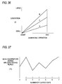
- Fig. 36 is a graph showing heat dissipation patterns used in this conventional heat storage air conditioner.
- Fig. 37 is a graph illustrating one example of transitive temperature data obtained during air-conditioning periods.
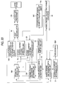
- reference numeral 1 designates a heat source; 2, a heat accumulator; 3, operation control unit for controlling the operations of the heat source 1 and the heat accumulator 2; 4, a cold/hot air discharger; 5, a remaining ice/hot-water quantity detection unit for detecting the quantity of remaining ice or hot water; and 6, dissipation pattern setting unit for setting a dissipation pattern of the heat accumulator 2.
- a path for use in supplying cooling/heating energy is designated by a broken line, whereas an information signal path is designated by a solid line (these paths will be hereinafter thus distinguished from each other).
- the heat source 1 performs heat storage operations during the night under control of the operation control unit 3, whereby cooling or heating energy is produced.
- the thus-produced cooling or heating energy is stored in the heat accumulator 2 through the cooling/heating energy path.
- the water previously held in the heat accumulator 2 changes to ice using the cooling energy or to hot water using the heating energy with lapse of time.
- the heat accumulator 2 performs dissipating operations during the daytime under control of the operation control unit 3.
- the cooling energy of ice or the heating energy of hot water stored in the heat accumulator 2 during the night is sent to the heated/cooled air discharger 4 via the heating/cooling energy path.
- This heating/cooling energy is dissipated from the heated/cooled air discharger 4, thereby cooling or heating a living space. If the thermal energy load of the living space required during the air-conditioning periods cannot be sufficiently met by the dissipating operations of the heat accumulator 2, the thermal energy load for the living space will be covered by addition of the dissipating operations of the heat source 1.
- the operation control unit 3 receives information about the quantity of ice or hot water remaining in the heat accumulator 2 from the remaining ice/hot-water quantity detection unit 5 in order to perform dissipation control operations. The thus-received information is compared with the dissipation pattern set by the dissipation pattern setting unit 6. If the quantity of thermal energy to be dissipated is determined to be large, the heat accumulator 2 performs dissipating operations such that dissipation pattern C shifts to dissipating operation pattern A shown in Fig. 36, namely, such that the quantity of thermal energy to be dissipated becomes smaller.
- the heat accumulator 2 performs dissipating operations such that the dissipation pattern C shifts to dissipation pattern B shown in Fig. 36, namely, such that the quantity of thermal energy to be dissipated becomes larger.
- the time period between the starting time and the stop time of the operations of the cold/hot air discharger 4 is divided into a plurality of smaller time segments.
- the quantity of thermal energy to be dissipated is previously determined with regard to each of these time segments.
- Several patterns are provided as the dissipation pattern so as to meet various thermal energy load requirements of the living space.
- the conventional heat storage air conditioner determines the quantity of dissipation of the cooling/heating energy stored during the night, only on the basis of the state of thermal energy load of the living space immediately before the current time. If the quantity of thermal energy to be dissipated from the heat accumulator 4 is large; namely, if the temperature of the living space is set to a high level, the quantity of thermal energy to be dissipated is determined so as to decrease with no regards to the demand. If the quantity of thermal energy to be dissipated from the heat accumulator 4 is small; namely, if the temperature of the living space is set a low level, the quantity of thermal energy to be dissipated is determined so as to increase with no regards to the demand.
- the quantity of thermal energy to be dissipated is determined with no regards to the temperature settings of the living space. Further, the power of the heat storage air conditioner has not been estimated, making it impossible to appropriately set the dissipation pattern even if it is desired to control the quantity of electric power on the basis of demand.
- It is an object of the present invention is to make it possible to estimate the quantity of electric power that is required in the short-term future, to effect demand-based control of the quantity of electric power to be used, and to sufficiently maintain the amenity of a living space by calculating the quantity of electric power to be used from thermal load of the living space during the daytime, and matching the thus-calculated quantity of electric power with the trends of variations of the past.
- a heat storage air conditioning apparatus is comprised of: a power demand time-sequence data collecting unit for collecting time-sequence data on demand for power; a power demand curve estimating unit for estimating a power demand curve obtained as a result of analysis of the power demand time-sequence data collected by the power demand time-sequence data collecting unit; thermal energy load demand estimating unit for estimating thermal energy load demand from the power demand curve estimated by the power demand curve estimating unit; an operation unit of a thermal-energy source for feeding cooling/heating energy; a heat accumulating unit for storing the cooling/heating energy supplied from the operation unit therein; a cold/hot air discharging unit for discharging the thermal energy stored in the heat accumulating unit; a cooling/heating energy quantity recognizing unit for recognizing the quantity of cooling or heating energy dissipated from the cold/hot air discharging unit; and a converting unit for converting the quantity of cooling/heating energy into the quantity of electric power, the converted quantity of electric
- a heat storage estimating method is comprised of the steps of: detecting or calculating the quantity of cooling/heating energy that is equivalent to the quantity of thermal energy to be accumulated; converting the quantity of thermal energy to be accumulated, which is recognized in the recognizing step, into the quantity of electric power; collecting time-sequence data on power demand, taking the quantity of the power converted in the converting step as the power demand; estimating a power demand curve by analyzing the power demand time-sequence data collected in the collecting step; and estimating thermal-energy load demand from the power demand curve estimated in the power demand curve estimating step.
- the heat storage air conditioning apparatus and the heat storage estimating method of the present invention there is no shortage or surplus of the stored thermal energy amount during air conditioning operation period. Accordingly, the amenity of the living space can be sufficiently maintained, and the electric power during night can be effectively utilized. In addition, because the whole of the electric power necessary in cooling or heating operation is covered by the stored thermal energy, the electricity charges can be saved.
- Fig. 1 is a basic block diagram of a heat storage air conditioner according to the present invention.
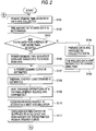
- Figs. 2 and 3 are flowcharts for use in describing processing operations of the heat storage air conditioner.
- Fig. 4 is a diagram for explaining a method of estimating a power demand curve for the next day using pseudo data of the heat storage air conditioner.
- Fig. 5 is a table that shows an example of numerical values regarding the quantity of power electricity represented by the pseudo data.
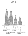
- Fig. 6 is an example of repetitive heat quantity pattern used in the heat storage air conditioner of the first embodiment.
- reference numeral 11 designates a power demand time-sequence data collecting unit for collecting power demand time-sequence data.
- Reference numeral 31 designates stored data amount determination unit that determines the amount of data stored by the power demand time-sequence data collecting unit 11. If a predetermined amount of stored data (e.g., 60 days' worth of data) has not been achieved yet, the stored data amount determination unit sends pseudo data 32 to the power demand time-sequence data collecting unit 11.
- a predetermined amount of stored data e.g. 60 days' worth of data
- the stored data amount determination unit sends pseudo data 32 to the power demand time-sequence data collecting unit 11.
- Reference numeral 12 designates a power demand curve estimating unit for estimating the power demand curve that is obtained by subjecting the power demand time-sequence data collected by the power demand time-sequence data collecting unit 11 or the pseudo data 32 to Chaos Analysis, which is one example of a method of analyzing the power demand time-sequence data.
- Reference numeral 13 designates thermal energy load demand estimating unit that estimates thermal energy load demand from the power demand curve; 14, heat storage operation unit of a heat source that stores cooling/heating energy in a heat accumulator 15 through a cooling/heating energy path; 16, stored heat utilizing operation unit for utilizing the thermal energy stored in the heat accumulator 15; 17, a cold/hot air discharger for dissipating the thermal energy stored in the heat accumulator 15; and 18, operation control unit for controlling the heat storage operation unit 14 and the stored energy utilizing operation unit 16 of the heat source.
- the operation control unit 18 controls the heat storage operation unit 14 of the heat source on the basis of the thermal energy load demand estimated by the heat demand estimating unit 13 so as to cause the heat accumulator 15 to store the cooling/heating energy corresponding to the thermal energy load demand during the night.
- the power demand curve estimating unit 12 controls the stored heat utilizing operation unit 16 so as to cause the heat accumulator 15 to supply the stored thermal energy to the cold/hot air discharger 17 through the cooling/heating energy path during air-conditioning periods.
- Reference numeral 19 designates cooling/heating energy quantity detection unit that detects the quantity of cooling/heating energy dissipated from the heat accumulator 15 through the cold/hot air discharger 17.
- the cooling/heating energy quantity detection unit 19 detects (or calculates) the quantity of cooling/heating energy by unit of a temperatures sensor 21 for detecting the temperature of the air discharged from the cold/hot air discharger 17 and a built-in timer 19a.
- Reference numeral 22 designates a heat-to-electric-power converter that converts the quantity of cooling or heating energy detected by the cooling/heating energy quantity detection unit 19 into the quantity of electric power, as well as sending the thus-converted electric power to the power demand time-sequence data collecting unit 11.
- the operation of the heat storage air conditioner of the first embodiment will be described on the basis of Figs. 2 and 3.
- the power demand time-sequence data collecting unit 11 collects power demand time-sequence data in the time period during which a living space is air-conditioned (step 101).
- the stored data amount determination unit 31 determines the amount of data stored by the power demand time-sequence data collecting unit 11 (step 102). In the case where the heat storage air conditioner starts up for the first time or recovers to its original state after the previous data have been lost as a result of a power failure, the stored data are substantially zero.
- the stored data amount determination unit 31 constantly monitors whether or not the amount of data stored by the power demand time-sequence data collecting unit 11 corresponds to a period of time more than 60 days (step 103). If the stored data amount determination unit 31 decides that the amount of stored data corresponds to a period of time less than 60 days, the heat storage air conditioner will be judged as being in an initial start-up condition or a recovery condition after a power failure. As a result, the pseudo data 32 are supplied to the power demand time-sequence data collecting unit 11, and the power demand time-sequence data collecting unit 11 takes the thus-received pseudo data as the collected data (step 104). The power demand curve estimating unit 12 analyzes the pseudo data 32 using Chaos Analysis (step 105).
- the power demand curve estimating unit 12 analyzes the thus-collected power demand time-sequence data using Chaos Analysis (step 106).
- the power demand curve estimating unit 12 analyzes the power demand time-sequence data or the pseudo data 32 using Chaos Analysis, whereby a power demand curve during the air-conditioning periods for the next day is estimated (step 107).
- the thermal energy load demand estimating unit 13 estimates the thermal energy load required during the cooling or heating period for the next day on the basis of the power demand curve estimated by the power demand curve estimating unit 12 (step 108).
- the operation control unit 18 controls the heat storage unit 14 of the heat source, on the basis of the thermal energy load demand estimated by the thermal energy load demand estimating unit 13, so as to perform heat storage operations during the night (step 109). Then, the water previously stored in the heat accumulator 15 changes to ice using cooling energy or to hot water using heating energy with lapse of time, whereby the resultant ice or hot water is stored in the heat accumulator 15 (step 110).
- the operation control unit 18 controls the stored heat utilizing operation unit 16 during the air-conditioning period on the next day on the basis of the power demand curve estimated by the power demand curve estimating unit 12, whereby the stored thermal energy of the heat accumulator 15 is supplied to the cold/hot air discharger 17 through the cooling/heating energy path (step 111).
- the thermal energy is dissipated from the cold/hot air discharger 17 (step 112), which enables the living room to be cooled or heated.
- the cooling/heating energy quantity detection unit 19 detects the quantity of cooling energy of ice or the quantity of heating energy of hot water supplied to the cold/hot air discharger 17, in time sequence, by unit of the temperature sensor 21 for detecting the temperature of the air dissipated from the cold/hot air discharger 17 and the built-in timer 19a (step 113).
- the data on the quantity of cooling/heating energy detected in time sequence is input to the heat-to-electric-power converter 22.
- the data on the quantity of cooling/heating energy are converted into data on the quantity of electric power by unit of the heat-to-electric-power converter 22 (step 114).
- the time-sequence data on the quantity of electric power converted by the heat-to-electric-power converter 22 are supplied to the power demand time-sequence data collecting unit 11.
- the thus-received time-sequence data are collected again as the power demand time-sequence data in the same manner as has been previously described in step 101.
- the same processing as has been previously described is repeated hereinbelow.
- heat storage quantity pattern "a” corresponds to heat dissipation quantity pattern "b” during air-conditioning periods for the next day.
- heat storage quantity pattern “c” corresponds to heat quantity dissipation pattern "d” during the air-conditioning periods for the next day.
- the operation control unit 18 is set so as to complete the heat storage operations of the heat source carried out by the heat storage operation unit 14 of the heat source in step 109 immediately before the air-conditioning periods during which a cooling or heating operation commences.
- a cooling or heating operation i.e., a cooling or heating operation
- the thermal energy as previously set, which makes it possible to prevent the quantity of thermal energy stored in the heat accumulator 15 from running short during the air-conditioning periods as well as sufficiently maintaining the amenity of the living space.
- the same also applies to the second through eighth embodiments which will be described later.
- the stored data amount determination unit 31 constantly monitors the amount of data stored by the power demand time-sequence data collecting unit 11. If it is decided that the amount of stored data corresponds to a period of time less than 60 days, the pseudo data 32, which comprises the time-sequence data (e.g., 60 days' worth of data) regarding the power of a very-analogous system having the same scale is sent to the power demand time-sequence data collecting unit 11. A estimate for the subsequent power demand is controlled using the pseudo data 32 as the collected data. Therefore, the estimate-based control operations can be started without any problems even in the case where the heat storage air conditioner starts up or recovers to its original state after a power failure.
- the pseudo data 32 which comprises the time-sequence data (e.g., 60 days' worth of data) regarding the power of a very-analogous system having the same scale is sent to the power demand time-sequence data collecting unit 11.
- a estimate for the subsequent power demand is controlled using the pseudo data 32 as the collected data.
- Fig. 4 shows the previous power demand time-sequence pseudo data (i.e., pseudo data) and the current power demand time-sequence data.
- pseudo data the previous power demand time-sequence pseudo data
- the current power demand time-sequence data For example, a local pattern of the pseudo data, which is most analogous to a local pattern of the current day's power demand time-sequence data obtained when the air-conditioning operation approaches completion, is extracted. If the local pattern of the power demand time-sequence data obtained ten days before is most analogous to the current day's local pattern, this local pattern is treated as candidate data for use in Chaos Analysis.
- the time-sequence data one day after the time-sequence data obtained ten days before, i.e., the power demand time-sequence data obtained nine days before, are handled as the power demand curve.
- a local pattern of the previous power demand time-sequence data (i.e., pseudo data), which is most analogous to a local pattern of the power demand time-sequence data at the beginning of the air condition operation, may be extracted.
- pseudo data which is most analogous to a local pattern of the power demand time-sequence data at the beginning of the air condition operation
- the stored data amount determination unit 31 sends the time sequence data (being 60 days' worth of data) on the power of a very-analogous system having the same scale (e.g., an stored heat fully utilizing operation system) to the power demand time-sequence data collecting unit 11, exactly as they are, without updating them until the amount of data stored by the power demand time-sequence data collecting unit 11 becomes so as to correspond to a period of time more than 60 days. It is also possible for the stored data amount determination unit to take practical data as the most recent data among the pseudo data every time the practical data are obtained as a result of the air-conditioning operations.
- the pseudo data may be updated by deleting the oldest data corresponding to the quantity of most recent data.
- the contents of the pseudo data can be replaced with practical data with lapse of time. Therefore, it is possible to more smoothly shift the estimate-based control operations based on the pseudo data to the estimate-based control operations based on the practical data.
- the second embodiment which will be described later.
- the stored data amount determination unit can suspend the output of the pseudo data to the power demand time-sequence data collecting unit immediately after the amount of data practically obtained as a result of the air-conditioning operations has reached the amount (e.g., data for a period of one day) that permits estimate-based control operations.
- the estimate-based control operations based on the practical data are started when the amount of practical data is small. Only the contents of the data that are sufficient to make the heat storage air conditioner active are required as the pseudo data, which in turn makes it easy to sample the pseudo data from the very-analogous system having the same scale. The same also applies to the second embodiment that will be described later.
- Fig. 7 is a basic block diagram of a heat storage air conditioner according to the present invention.
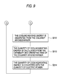
- Figs. 8 and 9 are flowcharts for use in describing processing operations of the heat storage air conditioner.
- the elements shown in Fig. 7 that are the same as those of the previously-described first embodiment shown in Fig. 1 are assigned the same reference numerals.
- reference numeral 11 designates a power demand time-sequence data collecting unit for collecting power demand time-sequence data.
- Reference numeral 31 designates stored data amount determination unit that determines the amount of data stored by the power demand time-sequence data collecting unit 11. If a predetermined amount of stored data (e.g., 60 days' worth of data) has not been achieved yet, the stored data amount determination unit sends pseudo data 32 to the power demand time-sequence data collecting unit 11. As in the first embodiment, the following descriptions will be based on an example wherein the time-sequence data (60 days' worth of data) regarding the power of a very-analogous system having the same scale are used as the pseudo data 32.
- Reference numeral 12 designates a power demand curve estimating unit for estimating the power demand curve that is obtained by subjecting the power demand time-sequence data collected by the power demand time-sequence data collecting unit 11 or the pseudo data 32 to Chaos Analysis, which is one example of a method of analyzing the power demand time-sequence data.
- Reference numeral 13 designates thermal energy load demand estimating unit that estimates thermal energy load demand from the power demand curve; 14, heat storage operation unit of a heat source that stores cooling/heating energy in a heat accumulator 15 through a cooling/heating energy path; 16, stored heat utilizing operation unit for utilizing the thermal energy stored in the heat accumulator 15; 17, a cold/hot air discharger for dissipating the thermal energy stored in the heat accumulator 15; and 18, operation control unit which has the same function as the operation control unit of the previously-described first embodiment.
- This operation control unit 18 controls the heat storage operation unit 14 and the stored heat utilizing operation unit 16.
- Reference numeral 19A designates cooling/heating energy quantity calculating unit for calculating the quantity of cooling/heating energy of the heat accumulator 15 dissipated from the cold/hot air discharger 17.
- This cooling/heating energy quantity calculating unit 19A has the function of calculating the quantity of cooling/heating energy from the capability and operating time of the hot/cold air discharger 17.
- Reference numeral 22 designates a heat-to-electric-power converter that converts the quantity of cooling or heating energy calculated by the cooling/heating energy quantity calculating unit 19A into the quantity of electric power, as well as sending the thus-converted electric power to the power demand time-sequence data collecting unit 11.
- the power demand time-sequence data collecting unit 11 collects power demand time-sequence data in the time period during which a living space is air-conditioned (step 201).
- the stored data amount determination unit 31 determines the amount of data stored by the power demand time-sequence data collecting unit 11 (step 202).
- the stored data amount determination unit 31 constantly monitors whether or not the amount of data stored by the power demand time-sequence data collecting unit 11 corresponds to a period of time more than 60 days (step 203).
- the stored data amount determination unit 31 decides that the amount of stored data corresponds to a period of time less than 60 days, the heat storage air conditioner will be judged as being in a start-up condition or a recovery condition after a power failure.
- the pseudo data 32 are supplied to the power demand time-sequence data collecting unit 11, and the power demand time-sequence data collecting unit 11 takes the thus-received pseudo data 32 as the collected data (step 204).
- the power demand curve estimating unit 12 analyzes the pseudo data 32 using Chaos Analysis (step 205).
- the power demand curve estimating unit 12 analyzes the thus-collected power demand time-sequence data using Chaos Analysis (step 206).
- the power demand curve estimating unit 12 analyzes the power demand time-sequence data or the pseudo data 32 using Chaos Analysis, whereby a power demand curve during the air-conditioning periods for the next day is estimated (step 207). Subsequently, the thermal energy load demand estimating unit 13 estimates the thermal energy load required during the cooling or heating period for the next day on the basis of the power demand curve estimated by the power demand curve estimating unit 12 (step 208).
- the operation control unit 18 controls the heat storage unit 14 of the heat source, on the basis of the thermal energy load demand estimated by the thermal energy load demand estimating unit 13, so as to perform heat storage operations during the night (step 209). Then, the water previously stored in the heat accumulator 15 changes to ice using cooling energy or to hot water using heating energy with lapse of time, whereby the resultant ice or hot water is stored in the heat accumulator 15 (step 210).
- the operation control unit 18 controls the stored heat utilizing operation unit 16 during the air-conditioning period on the next day on the basis of the power demand curve estimated by the power demand curve estimating unit 12, whereby the stored thermal energy of the heat accumulator 15 is supplied to the cold/hot air discharger 17 through the cooling/heating energy path (step 211).
- the thermal energy is dissipated from the cold/hot air discharger 17 (step 212), which enables the living room to be cooled or heated.
- the cooling/heating energy quantity calculating unit 19A calculates the quantity of cooling energy of ice or the quantity of heating energy of hot water supplied to the cold/hot air discharger 17 from the capability and operating time of the cold/hot air discharger 17 in time sequence (step 213).
- the data on the quantity of cooling/heating energy calculated in time sequence is input to the heat-to-electric-power converter 22. Consequently, the data on the quantity of cooling/heating energy are converted into data on the quantity of electric power by unit of the heat-to-electric-power converter 22 (step 214).
- the time-sequence data on the quantity of electric power converted by the heat-to-electric-power converter 22 are supplied to the power demand time-sequence data collecting unit 11.
- the thus-received time-sequence data are collected again as the power demand time-sequence data in the same manner as has been previously described in step 201.
- the same processing as has been previously described is repeated hereinbelow.
- the stored data amount determination unit 31 constantly monitors the amount of data stored by the power demand time-sequence data collecting unit 11. If it is decided that the amount of stored data corresponds to a period of time less than 60 days, the pseudo data 32, which comprises the time-sequence data regarding the power of a system being closely analogous to and having the same scale (e.g., 60 days' worth of data), is sent to the power demand time-sequence data collecting unit 11. A estimate for the subsequent power demand is controlled using the pseudo data 32 as the collected data. Therefore, the estimate-based control operations can be started without any problems even in the case where the heat storage air conditioner starts up or recovers to its original state after a power failure.
- the heat quantity patterns of the night and the heat dissipation quantity pattern of the air-conditioning periods of the next day are determined by analysis of the previous time-sequence data and the pseudo data 32. Consequently, the stored thermal energy can be prevented from running short or becoming excessive during the air-conditioning periods. Even if the stored thermal energy runs short or becomes excessive, the shortage or surplus of the thermal energy can be reduced. For these reasons, it is possible to use an appropriate quantity of electric power in producing thermal energy to be stored during the night as well as sufficiently maintaining the amenity of the living space. The quantity of electric power required during the cooling or heating periods is totally covered by the quantity of stored thermal energy, which in turn makes it possible to reduce electricity costs to a much greater extent.
- This cooling/heating energy quantity calculating unit 19A calculates the quantity of cooling energy of ice or the quantity of heating energy of hot water supplied to the cold/hot air discharger 17 from the heat accumulator 15, from the capability and operating time of the cold/hot air discharger 17 in time sequence. Therefore, the need for a temperature sensor can be eliminated, and the cost of the heat storage air conditioner can be reduced accordingly.
- Fig. 10 is a basic block diagram of a heat storage air conditioner according to the present invention.
- Figs. 11 and 12 are flowcharts for use in describing processing operations of the heat storage air conditioner.
- Fig. 13 is a diagram for use in describing a method of estimating a power demand curve for the next day using pseudo data of the heat storage air conditioner.
- Fig. 14 is a table that shows an example of numerical values regarding the quantity of power electricity represented by the pseudo data used in the heat storage air conditioner of the third embodiment.
- Fig. 11 and 12 are flowcharts for use in describing processing operations of the heat storage air conditioner.
- Fig. 13 is a diagram for use in describing a method of estimating a power demand curve for the next day using pseudo data of the heat storage air conditioner.
- Fig. 14 is a table that shows an example of numerical values regarding the quantity of power electricity represented by the pseudo data used in the heat storage air conditioner of the third embodiment.
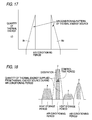
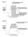
- FIG. 15 is a diagram showing a composite heat quantity pattern that is used in the heat storage air conditioner of the present invention and consists of the quantity of thermal energy defined by dissipating operation pattern A of a heat accumulator and the quantity of thermal energy defined by patterns B1 and B2 obtained at the time of air-conditioning operations of a heat source.
- Fig. 16 is a diagram showing the dissipating operation pattern A of the heat accumulator that corresponds to a hatched area of the composite heat quantity pattern shown in Fig. 15.
- Fig. 17 is a diagram showing the patterns B1 and B2 that are obtained at the time of the air-conditioning operations of the heat source and correspond to outlined portions of the composite heat quantity pattern shown in Fig. 15.
- Fig. 16 is a diagram showing the dissipating operation pattern A of the heat accumulator that corresponds to a hatched area of the composite heat quantity pattern shown in Fig. 15.
- Fig. 17 is a diagram showing the patterns B1 and B2 that are obtained at
- Fig. 18 is an example of repetitive heat quantity pattern used in the heat storage air conditioner of the third embodiment.
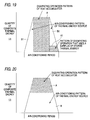
- Fig. 19 is a diagram illustrating an example of composite heat quantity pattern including pattern Al that uses a surplus of thermal energy.
- the elements shown in Fig. 10 that are the same as those used in the previously-described first embodiment shown in Fig. 1 are assigned the same reference numerals.
- reference numeral 11 designates a power demand time-sequence data collecting unit for collecting power demand time-sequence data.
- Reference numeral 31 designates stored data amount determination unit that determines the amount of data stored by the power demand time-sequence data collecting unit 11. If a predetermined amount of stored data (e.g., 60 days' worth of data) has not been achieved yet, the stored data amount determination unit sends pseudo data 32A to the power demand time-sequence data collecting unit 11.
- a predetermined amount of stored data e.g., 60 days' worth of data
- Reference numeral 12 designates a power demand curve estimating unit for estimating the power demand curve that is obtained by subjecting the power demand time-sequence data, that have been collected by the power demand time-sequence data collecting unit 11, or the pseudo data 32A to Chaos Analysis which is one example of a method of analyzing the power demand time-sequence data.
- Reference numeral 23 designates a demand control time setting unit for setting a control time period during which thermal energy load is covered by the stored thermal energy of the heat accumulator 15 on the basis of the power demand curve.
- Reference numeral 13A designates thermal energy load demand estimating unit that estimates thermal energy load demand of the control time period on the basis of the time control period set by the demand control time setting unit 23 and the power demand curve estimated by the power demand curve estimating unit 12.
- Reference numeral 14A designates operation unit of a heat source that supplies cooling/heating energy.
- Reference numeral 15 designates a heat accumulator that stores the cooling/heating energy received from the operation unit 14A of the heat source.
- Reference numeral 16 designates stored heat utilizing operation unit for utilizing the thermal energy stored in the heat accumulator 15; 17A, a cold/hot air discharger for dissipating the thermal energy stored in the heat accumulator 15 and/or the thermal energy received from the operation unit 14A of the heat source; and 18A, operation control unit controls the operation unit 14A and the stored heat utilizing operation unit 16. The detailed function of this operation control unit will be described later.
- Reference numeral 19B designates cooling/heating energy quantity detection unit that detects the quantity of cooling/heating energy dissipated from the heat accumulator 15 through the cold/hot air discharger 17A, from the thermal energy remaining in the heat accumulator 15.
- it is necessary to detect cooling energy (latent heat) and heating energy (sensible heat) in order to obtain the quantity of ice or hot water remaining in the heat accumulator 5.
- a water level sensor 24 is used for detecting the cooling energy (latent heat)
- a temperature sensor 25 is used for detecting the heating energy (sensible heat).
- the cooling/heating energy quantity detection unit 19B detects (or calculates) the quantity of cooling/heating energy dissipated from the heat accumulator 15 through the cold/hot air discharger 17A by comparing the residual thermal energy of the current heat accumulator 15 detected by the water level sensor 24 and the temperature sensor 25 with the thermal energy load demand estimated on the previous day by the thermal energy load demand estimating unit 13A.
- Reference numeral 26 designates stored heat utilization determination unit that determines the state of utilization of the stored thermal energy during the control time period of the air-conditioning periods, from the quantity of cooling/heating energy detected by the cooling/heating energy quantity detection unit 19B and the thermal energy load demand estimated by the thermal energy load estimating unit 13A.
- the stored heat utilization determination unit 26 sends a result of the determination to the operation control unit 18A.
- Reference numeral 22 designates a heat-to-electric-power converter that converts the quantity of cooling or heating energy detected by the cooling/heating energy quantity calculating unit 19B into the quantity of electric power, as well as sending the thus-converted electric power to the power demand time-sequence data collecting unit 11.
- the operation control unit 18A has the following functions of:
- the power demand time-sequence data collecting unit 11 collects power demand time-sequence data in the time period during which a living space is air-conditioned (step 301).
- the stored data amount determination unit 31 determines the amount of data stored by the power demand time-sequence data collecting unit 11 (step 302).
- the stored data amount determination unit 31 constantly monitors whether or not the amount of data stored by the power demand time-sequence data collecting unit 11 corresponds to a period of time more than 60 days (step 303).
- the stored data amount determination unit 31 decides that the amount of stored data corresponds to a period of time less than 60 days, the heat storage air conditioner will be judged as being in a start-up condition or a recovery condition after a power failure.
- the pseudo data 32A are supplied to the power demand time-sequence data collecting unit 11, and the power demand time-sequence data collecting unit 11 takes the thus-received pseudo data 32A as the collected data (step 304).
- the power demand curve estimating unit 12 analyzes the pseudo data 32A using Chaos Analysis (step 305).
- the power demand curve estimating unit 12 analyzes the thus-collected power demand time-sequence data using Chaos Analysis (step 306).
- the power demand curve estimating unit 12 analyzes the power demand time-sequence data or the pseudo data 32A using Chaos Analysis, whereby a power demand curve during the air-conditioning periods for the next day is estimated (step 307).
- the demand control time setting unit 23 previously sets the control time period during which thermal energy load is covered by the thermal energy stored in the heat accumulator 15, to a specific time period on the basis of the power demand curve estimated by the power demand curve estimating unit 12 (step 308).
- the operation control unit 18A determines the operation pattern (see Fig. 15) of the air-conditioning periods on the basis of the control time period and the estimated power demand curve (step 309).
- the thermal energy load demand estimating unit 13A estimates the thermal energy load required during the cooling or heating periods on the basis of the control time period and the estimated power demand curve (step 310).
- the control time period that has been previously set to a specific time period by the demand control time setting unit 23 is made so as to be capable of being fixed or changed.
- the operation control unit 18A controls the operation unit 14A of the heat source so as to cause the heat source to perform heat storage operations during the night in order to store the quantity of thermal energy, which is equivalent to the thermal energy load demand estimated by the thermal energy load demand estimating unit 13A, in the heat accumulator 15 through the cooling/heating energy path (step 311). Then, the water previously stored in the heat accumulator 15 changes to ice using cooling energy or to hot water using heating energy with lapse of time, whereby the resultant ice or hot water is stored in the heat accumulator 15 (step 312).
- the operation unit 14A of the heat source is initially controlled in accordance with pattern B1 (see Fig. 15) of the operation patterns determined by the operation control unit 18A so as to cause the heat source to perform operations (step 313).
- the cooling/heating energy of by the heat source is directly supplied to the cold/hot air discharger 17A through the cooling/heating energy path (step 314).
- the power demand time-sequence data of the heat source are supplied to the power demand time-sequence data collecting unit 11. Consequently, the cooling/heating energy received from the heat source is dissipated from the cold/hot air discharger 17A (step 315), thereby making it possible to cool or heat the living space.
- the direct supply of cooling/heating energy to the cold/hot air discharger 17A from the heat source is carried out immediately before the control time period within the air-conditioning period, as shown in Fig. 15.
- the supply of cooling/heating energy is temporarily suspended when the time control period commences.
- the operation control unit 18A controls the stored heat utilizing operation unit 16 according to the pattern A of the operation patterns (see Fig. 15) so as to carry out dissipating operations (step 316).
- the cooling/heating energy of the heat accumulator 15 is supplied to the cold/hot air discharger 17A via the cooling/heating path (step 317).
- the cooling/heating energy received from the heat accumulator 15 is dissipated from the cold/hot air discharger 17A (step 318), thereby making it possible to cool or heat the living space.
- the cooling/heating energy detection unit 19B detects, in time sequence, the quantity of cooling energy of ice or heating energy of hot water supplied to the cold/hot air discharger 17A, from the residual thermal energy (cooling or heating energy) of the current heat accumulator 15 detected by the water level sensor 24 and the temperature 25 and the thermal energy load demand estimated on the previous day by the thermal energy load demand estimating unit 13A (step 319).
- the data on the cooling/heating energy detected in time sequence are input to the heat-to-electric-power converter 22.
- the data on the cooling/heating energy are converted into the data on the quantity of electric power by the heat-to-electric-power converter 22 (step 320).
- the time-sequence data on the quantity of electric power converted by the heat-to-electric-power converter 22 are supplied to the power demand time-sequence data collecting unit 11.
- the thus-output time-sequence data are collected again as power demand time-sequence data in the same manner as previously described in step 301.
- the control operation unit 18A stops the dissipating operations of the stored heat utilizing operation unit 16.
- the control operation unit 18A again controls the operation unit 14A of the heat source according to pattern B2 (see Fig. 15) of the operation patterns so as to cause the heat source to perform operations.
- the cooling/heating energy of the heat source is directly supplied to the cold/hot air discharger 17A through the cooling/heating energy path.
- the time-sequence data on the quantity of electric power dissipated from the heat source at this time are supplied to the power demand time-sequence data collecting unit 11.
- the cooling/heating energy received again from the heat source is dissipated from the cold/hot air discharger 17A, thereby making it possible to cool or heat the living space.
- the re-supply of cooling/heating energy to the cold/hot air discharger 17A from the thermal-air discharger is carried out until the air-conditioning periods shown in Fig. 15 complete.
- the supply of cooling/heating energy is terminated when the time control period completes.
- a resident of the living space often sets the temperature of a room to a lower level at the time of air-conditioning operations.
- the thermal energy load actually used in air-conditioning operations becomes smaller than the thermal energy load demand previously estimated by the thermal energy load demand estimating unit 13A.
- the stored heat utilization determination unit 26 determines the state of utilization of the stored thermal energy during the control time period of the air-conditioning periods, from the quantity of cooling/heating energy detected by the cooling/heating energy quantity detection unit 19B and the thermal energy load demand estimated by the thermal energy load estimating unit 13A (step 321).
- the operation control unit 18A If there is a surplus of stored thermal energy after the dissipation of the stored thermal energy of the heat accumulator 15 (step 322), the operation control unit 18A is notified of the surplus of stored thermal energy.
- the operation control unit 18A sets pattern Al regarding a dissipating operation which utilizes the surplus of stored thermal energy, in the remaining time period after the control time period of the air-conditioning periods set by the demand control time setting unit 23, as shown in Fig. 19.
- the operation control unit 18A controls the stored heat utilization determination unit 16 so as to perform dissipating operations based on the pattern Al together with the air-conditioning operation (pattern B2) of the heat source (step 323).
- the surplus of stored thermal energy of the heat accumulator 15 is supplied to the cold/hot air discharger 17A via the cooling/heating energy path (step 324).
- the surplus of stored cooling/heating energy received from the heat accumulator 15 is dissipated from the cold/hot air discharger 17A (step 325).
- the thus-dissipated cooling/heating energy is utilized in cooling or heating the living space. It goes without saying that the load of pattern B2 placed on the heat source during the air-conditioning periods is mitigated as a result of the dissipating operation that is carried out together with the air-conditioning operation with use of the surplus of stored thermal energy (pattern A1).
- step 322 If it has been determined in step 322 that there is not any surplus of stored thermal energy after the dissipation of thermal energy from the heat accumulator 15, return to step 302 takes place.
- the stored data amount determination unit 31 again determines the amount of power demand time-sequence data collected by the power demand time-sequence data collecting unit 11.
- the surplus of stored thermal energy received from the heat accumulator 15 is dissipated from the cold/hot air discharger 17A in step 325, return to step 319 takes place.
- the cooling/heating energy quantity detection unit 19B detects, in time sequence, the quantity of cooling energy of ice or heating energy of hot water that corresponds to the surplus of stored thermal energy supplied to the cold/hot air discharger 17A.
- the quantity of cooling/heating energy that corresponds to the surplus of stored thermal energy and has been detected in time sequence is converted into the data on the quantity of electric power in step 320.
- the thus-converted data are supplied to the power demand time-sequence data collecting unit 11 and are collected again as the power demand time-sequence data.
- the same processing as has been previously described is repeated hereinbelow.
- heat storage quantity pattern "a” corresponds to heat dissipation quantity pattern "b” during an air-conditioning period on the next day.
- heat storage quantity pattern “c” corresponds to heat dissipation quantity pattern “d” during an air-conditioning period on the next day.
- the stored data amount determination unit 31 constantly monitors the amount of data stored by the power demand time-sequence data collecting unit 11. If the stored data amount determination unit 31 decides that the amount of stored data corresponds to a period of time less than 60 days, the pseudo data 32A consisting of very-analogous theoretical time-sequence data (e.g., 60 days' worth of data) are supplied to the power demand time-sequence data collecting unit 11. A estimate for the subsequent power demand is controlled using the pseudo data 32A as the collected data. Therefore, the estimate-based control operations can be started without any problems even in the case where the heat storage air conditioner starts up or recovers to its original state after a power failure.
- very-analogous theoretical time-sequence data e.g. 60 days' worth of data
- the above embodiment has been described on the basis of an example of dissipating operation that utilizes the surplus of stored thermal energy, that is, the pattern Al (see Fig. 19) that utilizes a surplus of stored thermal energy during the remaining time period after the control time period of the air-conditioning periods while averaging it.
- the present invention is not limited to this embodiment.
- the time period, during which dissipating operations are carried out using a surplus of stored thermal energy is set to a specific time period within the remaining time period after the control time period of the air-conditioning operations. It is also possible to dissipate all of the surplus of stored thermal energy at one time during that specific time period.
- the third embodiment has been described using the stored data amount determination unit 31 having the following arrangement as an example.
- the stored data amount determination unit 31 is arranged so as not to update very-analogous theoretical power demand time-sequence data (60 days' worth of data), i.e., the data for the system capable of carrying out the operations of the heat source together with the operations that use the stored thermal energy, until the amount of data stored by the power demand time-sequence data collecting unit 11 becomes so as to correspond to a period of time more than 60 days. That power demand time-sequence data are directly supplied to the power demand time-sequence data collecting unit 11.
- the stored data amount determination unit may be arranged so as to take practical data as the most recent data among the pseudo data every time the practical data are obtained as a result of the air-conditioning operations. Then, the pseudo data may be updated by deleting the oldest data corresponding to the quantity of most recent data. In this case, the contents of the pseudo data can be replaced with practical data with lapse of time. Therefore, it is possible to more smoothly shift the estimate-based control operations based on the pseudo data to the estimate-based control operations based on the practical data. The same also applies to the fourth, fifth, and eighth embodiments that will be described later.
- the stored data amount determination unit can suspend the output of the pseudo data to the power demand time-sequence data collecting unit immediately after the amount of data practically obtained as a result of the air-conditioning operations has reached the amount (e.g., data for a period of one day) that permits estimate-based control operations.
- the estimate-based control operations based on the practical data are started when the amount of practical data is small. Only the contents of the data that are sufficient to make the heat storage air conditioner active are required as the pseudo data, which in turn makes it easy to prepare theoretical pseudo data.
- the fourth, fifth, and eighth embodiments that will be described later.
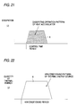
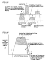
- Fig. 20 is a diagram illustrating an example of composite heat quantity pattern that is used in a heat storage air conditioner according to the present invention and includes the quantity of thermal energy defined by dissipating operation pattern A of the heat accumulator and the quantity of thermal energy defined by the air-conditioning operation pattern B of the heat source.
- Fig. 21 is a diagram showing the dissipating operation pattern A of the heat accumulator that corresponds to a hatched portion of the composite heat quantity pattern shown in Fig. 20.
- Fig. 22 is a diagram showing the air-conditioning operation pattern B of the heat source that corresponds to an outlined portion of the composite heat quantity pattern shown in Fig. 20.
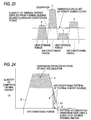
- FIG. 23 is a diagram illustrating an example of repetitive heat quantity pattern used in the heat storage air conditioner of the fourth embodiment.
- Fig. 24 is a diagram illustrating an example of composite heat quantity pattern including the pattern Al that uses a surplus of thermal energy.
- the heat storage air conditioner of the fourth embodiment has basically the same configuration as that of the previously described third embodiment shown in Fig. 10. Therefore, Fig. 10 will be referred to during the course of the description of the present embodiment.
- the heat storage air conditioner of the fourth embodiment is different from that of the previously described third embodiment in the following points: Specifically, the demand control time setting unit 23 sets the control time period during which thermal energy load is covered by the thermal energy of the heat accumulator 15 on the basis of the power demand curve estimated by the power demand curve estimating unit 12 shown in Fig. 10. This demand control time setting unit 23 is arranged so as to set a threshold value on the power demand curve as well as setting the control time period in the time period during which the power demand curve is in excess of the threshold value.
- the operation control unit 18A sets the pattern Al regarding the dissipating operations that uses a surplus of stored thermal energy, in a specific time period within the remaining time period after the control time period of the air-condition periods, as shown in Fig. 24. All of the surplus of stored thermal energy is dissipated at one time during that specific time period. The operations of the heat source are completely suspended during the time period of the dissipating operation that uses the surplus of stored thermal energy.
- the control time period is arranged so as to be capable of being fixed or changed when the demand control time setting unit 23 sets the threshold value on the power demand curve.
- heat storage quantity pattern "a” corresponds to heat dissipation quantity pattern "b” obtained during the control time period during which the power demand curve exceeds a threshold value in the air-conditioning period on the next day.
- heat storage quantity pattern "c” corresponds to heat dissipation quantity pattern “d” obtained during the control time period during which the power demand curve exceeds a threshold value in the air-conditioning period on the next day.
- the quantity of electric power that the heat source dissipates to cover the cooling/heating period within the extent in which the power demand does not exceed the threshold value can be significantly reduced. Further, the contract power demand required during the cooling or heating periods can be reduced, which makes it possible to reduce electricity costs to a much greater extent. Furthermore, the stored thermal energy can be prevented from running short or becoming excessive during the control time period of the air-conditioning periods. For example, even if the stored thermal energy runs short or becomes excessive, the shortage or surplus of the thermal energy can be reduced. Furthermore, if there arises a surplus of stored thermal energy, that surplus of stored thermal energy can be effectively utilized at the time of air-conditioning operations without natural diffusion of the surplus of stored thermal energy to the outside. For these reasons, it is possible to use an appropriate quantity of electric power in producing thermal energy to be stored during the night as well as sufficiently maintaining the amenity of the living space.
- the stored data amount determination unit 31 constantly monitors the amount of data stored by the power demand time-sequence data collecting unit 11. If the stored data amount determination unit 31 decides that the amount of stored data corresponds to a period of time less than 60 days, the pseudo data 32A consisting of very-analogous theoretical time-sequence data (e.g., 60 days' worth of data) are supplied to the power demand time-sequence data collecting unit 11. A estimate for the subsequent power demand is controlled using the pseudo data 32A as the collected data. Therefore, the estimate-based control operations can be started without any problems even in the case where the heat storage air conditioner starts up or recovers to its original state after a power failure.
- very-analogous theoretical time-sequence data e.g. 60 days' worth of data
- the dissipating operation that uses a surplus of stored thermal energy has been described in the above embodiment.
- the pattern Al (see Fig. 24) is used as an example of dissipating operation, wherein a surplus of stored thermal energy is dissipated at one time in a specific time of the remaining time period after the time period (i.e., the control time period) during which the power demand curve is in excess of the threshold value in the air-conditioning period.
- the surplus of stored thermal energy may be utilized while being averaged, during the remaining time period after the control time period of the air-conditioning period, in the same manner as previously described in the third embodiment shown in Fig. 19.
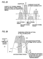
- Fig. 25 is a diagram illustrating a repetitive heat quantity pattern used in a heat storage air conditioner according to the present invention.
- Fig. 26 is a diagram illustrating an example of composite heat quantity pattern including dissipating operation pattern A3 that uses a surplus of thermal energy.
- the heat storage air conditioner has basically the same configuration as that of the previously described third embodiment shown in Fig. 10. Therefore, Fig. 10 will be referred to during the course of the description of the present embodiment.
- the heat storage air conditioner of the fifth embodiment is different from that of the previously described third and fourth embodiments in the following points: Specifically, the demand control time setting unit 23 sets the control time period during which thermal energy load is covered by the thermal energy of the heat accumulator 15 on the basis of the power demand curve estimated by the power demand curve estimating unit 12 shown in Fig. 10. This demand control time setting unit 23 is arranged so as to set a threshold value on the power demand curve as well as setting the control time period in the time period during which the power demand curve is in excess of the threshold value.
- the operation control unit 18A sets the pattern A3 regarding the dissipating operations that uses a surplus of stored thermal energy, in a specific time period within the remaining time period after the control period of the air-condition periods, i.e., a specific time period within the remaining time period after the time period during which the power demand curve is in excess the threshold value for the air-conditioning operations, as shown in Fig. 26. All of the surplus of stored thermal energy is dissipated at one time during that specific time period. The operations of the heat source are completely suspended during the time period of the dissipating operation that uses the surplus of stored thermal energy.
- the control time period is arranged so as to be capable of being fixed or changed when the demand control time setting unit 23 sets the threshold value on the power demand curve.
- Hatched area Al of the composite heat quantity pattern shown in Fig. 26 designates a dissipating operation pattern of the heat accumulator during the control time period that has previously been set to a specific time period.
- Hatched area A2 designates a dissipating operation pattern of the heat accumulator during the control time period set in the time period during which the power demand curve is in excess of the threshold value.
- Hatched area A3 designates a pattern regarding dissipating operations that use a surplus of stored thermal energy.
- Outlined areas B1 and B2 of the composite thermal energy quantity pattern respectively designate operation patterns at the time of the air-conditioning operations of the heat source.
- heat storage quantity pattern "a” corresponds to heat dissipation quantity patterns “b1” and “b2” obtained during the air-conditioning period on the next day.
- heat storage quantity pattern “c” corresponds to heat dissipation quantity patterns “d1” and “d2” obtained during the air-conditioning period on the next day.
- the contract power demand required during the cooling or heating periods can be reduced, which makes it possible to reduce electricity costs to a much greater extent.
- the stored thermal energy can be prevented from running short or becoming excessive during the control time period of the air-conditioning periods. For example, even if the stored thermal energy runs short or becomes excessive, the shortage or surplus of the thermal energy can be reduced. Furthermore, if there arises a surplus of stored thermal energy, that surplus of stored thermal energy can be effectively utilized at the time of air-conditioning operations without natural diffusion of the surplus of stored thermal energy to the outside. For these reasons, it is possible to use an appropriate quantity of electric power in producing thermal energy to be stored during the night as well as sufficiently maintaining the amenity of the living space.
- the stored data amount determination unit 31 constantly monitors the amount of data stored by the power demand time-sequence data collecting unit 11. If the stored data amount determination unit 31 decides that the amount of stored data corresponds to a period of time less than 60 days, the pseudo data 32A consisting of very-analogous theoretical time-sequence data (e.g., 60 days' worth of data) are supplied to the power demand time-sequence data collecting unit 11. A estimate for the subsequent power demand is controlled using the pseudo data 32A as the collected data. Therefore, the estimate-based control operations can be started without any problems even in the case where the heat storage air conditioner starts up or recovers to its original state after a power failure.
- very-analogous theoretical time-sequence data e.g. 60 days' worth of data
- the dissipating operation that uses a surplus of stored thermal energy has been described in the above embodiment.
- the pattern A3 is used as an example of dissipating operation, wherein a surplus of stored thermal energy is dissipated at one time during a specific period within the remaining time period after the time period during which the power demand curve is in excess of the threshold value for the air-conditioning operations.
- the surplus of stored thermal energy may be utilized while being averaged, during the remaining time period after the control time period during which the power demand curve is in excess of the threshold value for air-conditioning operations, in the same manner as previously described in the third embodiment shown in Fig. 19.
- Fig. 27 is a block diagram of a heat storage air conditioner according to the present invention.
- the heat storage air conditioner of the sixth embodiment has the function of being capable of setting an operation pattern to various forms by changing the control time period using the demand control time setting unit. This function is the same as that previously described in the third, fourth, and fifth embodiment, and therefore details of the setting of the operation pattern will be omitted here.
- the heat storage air conditioner of the present embodiment has the function of being capable of setting the dissipating operation pattern to various forms that utilize a surplus of stored thermal energy, by unit of the operation control unit. This function is also the same as that previously described in the third, fourth, and fifth embodiments. Hence, details of the setting of the dissipating operation pattern will be also omitted here.
- reference numeral 11 designates a power demand time-sequence data collecting unit for collecting power demand time-sequence data.
- Reference numeral 31A designates stored data amount determination unit that determines the amount of data stored by the power demand time-sequence data collecting unit 11. If a predetermined amount of stored data (e.g., data for a period of one day) has not been achieved yet, the stored data amount determination unit instructs the power demand time-sequence data collecting unit 11 to suspend an output to a estimate-based control system, as well as sending a data shortage signal to the power demand time-sequence data collecting unit 11.
- a predetermined amount of stored data e.g., data for a period of one day
- Reference numeral 12 designates a power demand curve estimating unit for estimating a power demand curve that is obtained by subjecting the power demand time-sequence data received from the power demand time-sequence data collecting unit 11 to Chaos Analysis which is one example of a method of analyzing the power demand time-sequence data.
- Reference numeral 23 designates a demand control time setting unit for setting a control time period during which thermal energy load is covered by the stored thermal energy of the heat accumulator 15 on the basis of the power demand curve.
- the demand control time setting unit has the function of being capable of setting the operation pattern to various forms.
- Reference numeral 13A designates thermal energy load demand estimating unit that estimates thermal energy load demand of the control time period on the basis of the time control period set by the demand control time setting unit 23 and the power demand curve estimated by the power demand curve estimating unit 12.
- Reference numeral 14A designates operation unit of a heat source that supplies cooling/heating energy.
- Reference numeral 15 designates a heat accumulator that stores the cooling/heating energy received from the operation unit 14A of the heat source.
- Reference numeral 16 designates stored heat utilizing operation unit for utilizing the thermal energy stored in the heat accumulator 15; and 17A, a cold/hot air discharger for dissipating the thermal energy stored in the heat accumulator 15 and/or the thermal energy received from the operation unit 14A of the heat source.
- Reference numeral 19B designates cooling/heating energy quantity detection unit that detects the quantity of cooling/heating energy dissipated from the heat accumulator 15 through the cold/hot air discharger 17A, from the thermal energy remaining in the heat accumulator 15.
- the quantity of cooling/heating energy is detected (or calculated) by comparing the thermal energy currently remaining in the heat accumulator 15 detected by the water level sensor 24 or the temperature sensor 25 with the thermal energy load demand estimated on the previous day by the thermal energy load demand estimating unit 13A.
- Reference numeral 26 designates stored heat utilization determination unit that determines the state of utilization of the stored thermal energy during the control time period of the air-conditioning periods, from the quantity of cooling/heating energy detected by the cooling/heating energy quantity detection unit 19B and the thermal energy load demand estimated by the thermal energy load estimating unit 13A.
- the stored heat utilization determination unit 26 sends a result of the determination to the operation control unit 18A.
- Reference numeral 22 designates a heat-to-electric-power converter that converts the quantity of cooling or heating energy detected by the cooling/heating energy quantity calculating unit 19B into the quantity of electric power, as well as sending the thus-converted electric power to the power demand time-sequence data collecting unit 11.
- Reference numeral 18A designates operation control unit for controlling the operation unit 14A and the stored heat utilizing operation unit 16.
- This operation control unit 18A also has the function of being capable of setting the dissipating operation pattern to various forms that utilize a surplus of stored thermal energy.
- the operation control unit 18A has the functions (1), (2), and (3) previously described in the third embodiment.
- Reference numeral 33 designates control unit for forcibly causing a heat source to operate at the time of air-conditioning operations.
- the control unit 33 controls the operation unit 14A of the heat source during the air-conditioning period so as to directly supply cooling/heating energy to the cold/hot air discharger 17A. Further, the control unit 33 sends the quantity of electric power dissipated from the thermal energy source at this time to the power demand time-sequence data collecting unit 11.
- control unit 33 controls the operation unit 14 of the heat source so as to directly supply cooling/heating energy to the cold/hot air discharger 17A, is fixed to a period of time between eight o'clock and seventeen o'clock.
- control unit 33 may be arranged so as to control the operation unit 14A of the heat source on the basis of a drive signal of a blower (not shown) of the cold/hot air discharger 17A.
- the stored data amount determination unit 31A constantly monitors the amount of data stored by the power demand time-sequence data collecting unit 11. If the amount of stored data corresponds to a period of time less than one day, the control unit 33 instructs the suspension of an output to the estimate-based control system, as well as controlling the operation unit 14A of the heat source so as to directly supply cooling/heating energy to the cold/hot air discharger 17A. Therefore, the heat storage air conditioner can cope with cases where it starts up or where the previous data required to carry out estimate-based control operations are lost as a result of a power failure. In short, if the heat storage air conditioner starts up, or if the previous data are lost, the heat storage air conditioner can operate by switching to an ordinary operation (i.e., an operation which does not carry out control operations based on a estimate).
- Time-sequence data on the quantity of electric power which the thermal energy source for directly supplying cooling/heating energy to the cold/hot air discharger 17A dissipates when being forcibly actuated are sent to and collected by the power demand time-sequence data collecting unit 11. Therefore, it is possible to store the time-sequence data on the quantity of electric power during a period of ordinary operation (i.e., the operation that does not carry out control operations based on a estimate), as well as smoothly shifting the operation to estimate-based control operations when a predetermined amount of stored power demand time-sequence data (e.g., data for a period of one day) has been achieved.
- a predetermined amount of stored power demand time-sequence data e.g., data for a period of one day
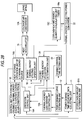
- Fig. 28 is a block diagram of a heat storage air conditioner according to the present invention.
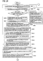
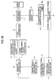
- Figs. 29 and 30 are flowcharts for use in describing processing operations of the heat storage air conditioner.
- Fig. 31 is a diagram for use in describing the method that estimates a power demand curve for the next day with use of power demand time-sequence data obtained when data are stored so as to correspond to a period of twelve days and eight hours.
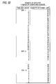
- Fig. 32 is a table that shows an example of numerical values regarding the quantity of power electricity represented by the time-sequence data.
- the same elements as those of the previously-described sixth embodiment shown in Fig. 27 are assigned the same reference numerals.
- the heat storage air conditioner has the function of being capable of setting the operation pattern to various forms by changing the control time period using the demand control time setting unit. This function is the same as that previously described in the third, fourth, and fifth embodiments. Consequently, the present embodiment will be described using only the previously-described operation pattern shown in Fig. 15 as an example. Furthermore, the heat storage air conditioner has the function of being capable of setting the dissipating operation pattern to various forms that utilize a surplus of stored thermal energy by unit of the operation control unit. This function is the same as that previously described in the third, fourth, and fifth embodiments. Consequently, the present embodiment will be described using only the previously-described dissipating operation pattern that utilizes a surplus of stored thermal energy and is shown in Fig. 19, as an example.
- reference numeral 11 designates a power demand time-sequence data collecting unit for collecting power demand time-sequence data.
- Reference numeral 31A designates stored data amount determination unit that determines the amount of data stored by the power demand time-sequence data collecting unit 11. If a predetermined amount of stored data (e.g., data for a period of one day) has not been achieved yet, the stored data amount determination unit instructs the power demand time-sequence data collecting unit 11 to suspend an output to a estimate-based control system, as well as sending a data shortage signal to the power demand time-sequence data collecting unit 11.
- a predetermined amount of stored data e.g., data for a period of one day
- Reference numeral 12 designates a power demand curve estimating unit for estimating a power demand curve that is obtained by subjecting the power demand time-sequence data received from the power demand time-sequence data collecting unit 11 to Chaos Analysis which is one example of a method of analyzing the power demand time-sequence data.
- Reference numeral 23 designates a demand control time setting unit for setting a control time period during which thermal energy load is covered by the stored thermal energy of the heat accumulator 15 on the basis of the power demand curve.
- the demand control time setting unit has the function of being capable of setting the operation pattern to various forms.
- Reference numeral 13A designates thermal energy load demand estimating unit that estimates thermal energy load demand of the control time period on the basis of the time control period set by the demand control time setting unit 23 and the power demand curve estimated by the power demand curve estimating unit 12.
- Reference numeral 14A designates operation unit of a heat source that supplies cooling/heating energy.
- Reference numeral 15 designates a heat accumulator that stores the cooling/heating energy received from the operation unit 14A of the heat source.
- Reference numeral 16 designates stored heat utilizing operation unit for utilizing the thermal energy stored in the heat accumulator 15; and 17A, a cold/hot air discharger for dissipating the thermal energy stored in the heat accumulator 15 and/or the thermal energy received from the operation unit 14A of the heat source.
- Reference numeral 19C designates cooling/heating energy quantity calculating unit that calculates the quantity of cooling/heating energy dissipated from the heat accumulator 15 through the cold/hot air discharger 17A, from the capability and operating time of the stored heat utilizing operation unit 16.
- Reference numeral 26 designates stored heat utilization determination unit that determines the state of utilization of the stored thermal energy during the control time period of the air-conditioning periods, from the quantity of cooling/heating energy calculated by the cooling/heating energy quantity calculating unit 19C and the thermal energy load demand estimated by the thermal energy load estimating unit 13A.
- the stored heat utilization determination unit 26 sends a result of the determination to the operation control unit 18A.
- Reference numeral 22 designates a heat-to-electric-power converter that converts the quantity of cooling or heating energy calculated by the cooling/heating energy quantity calculating unit 19C into the quantity of electric power, as well as sending the thus-converted electric power to the power demand time-sequence data collecting unit 11.
- Reference numeral 18A designates operation control unit for controlling the operation unit 14A and the stored heat utilizing operation unit 16.
- This operation control unit 18A also has the function of being capable of setting the dissipating operation pattern to various forms that utilize a surplus of stored thermal energy.
- the operation control unit 18A has the functions (1), (2), and (3) previously described in the third embodiment.
- Reference numeral 33 designates control unit for forcibly causing a heat source to operate at the time of air-conditioning operations.
- the control unit 33 controls the operation unit 14A of the heat source during the air-conditioning period (e.g., during a period of time between 8 o'clock and 17 o'clock) so as to directly supply cooling/heating energy to the cold/hot air discharger 17A. Further, the control unit 33 sends the quantity of electric power dissipated from the thermal energy source at this time to the power demand time-sequence data collecting unit 11.
- control unit 33 controls the operation unit 14 of the heat source so as to directly supply cooling/heating energy to the cold/hot air discharger 17A, is fixed to a period of time between eight o'clock and seventeen o'clock.
- control unit 33 may be arranged so as to control the operation unit 14A of the heat source on the basis of a drive signal of a blower (not shown) of the cold/hot air discharger 17A.
- the power demand time-sequence data collecting unit 11 collects power demand time-sequence data in the time period during which a living space is air-conditioned (step 401).
- the stored data amount determination unit 31A determines the amount of data stored by the power demand time-sequence data collecting unit 11 (step 402).
- the stored data amount determination unit 31A constantly monitors whether or not the amount of data stored by the power demand time-sequence data collecting unit 11 corresponds to a period of time more than one day (step 403).
- the stored data amount determination unit 31A decides that the amount of stored data corresponds to a period of time less than one day, a data short signal is sent to the control unit 33. Further, the stored data amount determination unit 31A instructs the power demand time-sequence data collecting unit 11 to prevent and suspend an output to a estimate-based control system (step 404). Upon notification of the shortage of data by the stored data amount determination unit 31A, the control unit 33 controls the operation unit 14A of the heat source so as to directly supply cooling/heating energy to the cold/hot air discharger 17A during the air-conditioning period (step 405). Then, the quantity of electric power dissipated by the heat source at this time is sent to and collected by the power demand time-sequence data collecting unit 11.
- the amount of storage of power demand time-sequence data regarding the quantity of electric power required when the heat source, which directly supplies cooling/heating energy to the cold/hot air discharger 17A during the air-condition period, is forcibly actuated amounts to a period of time more than one day
- the amount of stored power demand time-sequence data is determined as to correspond to a period of time more than one day in step 403.
- the output to the estimate-based control system from the power demand time-sequence data collecting unit 11 commences, and the power demand curve estimating unit 12 analyzes a small amount of power demand time-sequence data thus collected using Chaos Analysis (step 406).
- the power demand curve estimating unit 12 analyzes power demand time-sequence data using Chaos Analysis when the amount of collected data is small, whereby a power demand curve during the air-conditioning periods for the next day is estimated (step 407). Therefore, the accuracy of estimate for a power demand curve is improved as the amount of stored data increases, and the accuracy of estimate becomes stable when the data for a period of about 60 days are collected.
- the demand control time setting unit 23 previously sets the control time period during which thermal energy load is covered by the thermal energy stored in the heat accumulator 15, to a specific time period on the basis of the power demand curve estimated by the power demand curve estimating unit 12 (step 408).
- the operation control unit 18A determines the operation pattern (see Fig. 15) of the air-conditioning periods on the basis of the control time period and the estimated power demand curve (step 409).
- the thermal energy load demand estimating unit 13A estimates thermal energy load on the basis of the control time period and the estimated power demand curve (step 410).
- the control time period that has been previously set to a specific time period by the demand control time setting unit 23 is made so as to be capable of being fixed or changed.
- the operation control unit 18A controls the operation unit 14A of the heat source so as to cause the heat source to perform storage operations during the night in order to store the quantity of thermal energy, which is equivalent to the thermal energy load demand estimated by the thermal energy load demand estimating unit 13A, in the heat accumulator 15 through the cooling/heating energy path (step 411). Then, the water previously stored in the heat accumulator 15 changes to ice using cooling energy or to hot water using heating energy with lapse of time, whereby the resultant ice or hot water is stored in the heat accumulator 15 (step 412).
- the operation unit 14A of the heat source is initially controlled in accordance with pattern B1 (see Fig. 15) of the operation patterns determined by the operation control unit 18A so as to cause the heat source to perform operations (step 413).
- the cooling/heating energy of the heat source is directly supplied to the cold/hot air discharger 17A through the cooling/heating energy path (step 414).
- the time-sequence data on the quantity of electric power dissipated from the heat source at this time are supplied to the power demand time-sequence data collecting unit 11. Consequently, the cooling/heating energy received from the heat source is dissipated from the cold/hot air discharger 17A (step 415), thereby making it possible to cool or heat the living space.
- the direct supply of cooling/heating energy to the cold/hot air discharger 17A from the heat source is carried out immediately before the control time period within the air-conditioning period, as shown in Fig. 15.
- the supply of cooling/heating energy is temporarily suspended when the time control period commences.
- the operation control unit 18A controls the stored heat utilizing operation unit 16 according to the pattern A of the operation patterns (see Fig. 15) so as to carry out dissipating operations (step 416).
- the cooling/heating energy of the heat accumulator 15 is supplied to the cold/hot air discharger 17A via the cooling/heating path (step 417).
- the cooling/heating energy received from the heat accumulator 15 is dissipated from the cold/hot air discharger 17A (step 418), thereby making it possible to cool or heat the living space.
- the cooling/heating energy calculating unit 19C calculates, in time sequence, the quantity of cooling energy of ice or heating energy of hot water supplied to the cold/hot air discharger 17A, from the capability and operating time of the stored heat utilization unit 16 (step 419).
- the data on the cooling/heating energy calculated in time sequence are input to the heat-to-electric-power converter 22.
- the data on the cooling/heating energy are converted into the data on the quantity of electric power by the heat-to-electric-power converter 22 (step 420).
- the time-sequence data on the quantity of electric power converted by the heat-to-electric-power converter 22 are supplied to the power demand time-sequence data collecting unit 11.
- the thus-output time-sequence data are collected again as power demand time-sequence data in the same manner as previously described in step 401.
- the control operation unit 18A stops the dissipating operations of the stored heat utilizing operation unit 16.
- the control operation unit 18A again controls the operation unit 14A of the heat source according to pattern B2 (see Fig. 15) of the operation patterns so as to cause the heat source to perform operations.
- the cooling/heating energy of the heat source is directly supplied to the cold/hot air discharger 17A through the cooling/heating energy path.
- the time-sequence data on the quantity of electric power dissipated from the heat source at this time are supplied to the power demand time-sequence data collecting unit 11.
- the cooling/heating energy received again from the heat source is dissipated from the cold/hot air discharger 17A, thereby making it possible to cool or heat the living space.
- the re-supply of cooling/heating energy to the cold/hot air discharger 17A from the thermal-air discharger is carried out until the air-conditioning periods shown in Fig. 15 complete.
- the supply of cooling/heating energy is terminated when the time control period completes.
- the stored heat utilization determination unit 26 determines the state of utilization of the stored thermal energy during the control time period of the air-conditioning periods, from the quantity of cooling/heating energy calculated by the cooling/heating energy quantity calculating unit 19C and the thermal energy load demand estimated by the thermal energy load estimating unit 13A (step 421). If there is a surplus of stored thermal energy after the dissipation of the stored thermal energy of the heat accumulator 15 (step 422), the operation control unit 18A is notified of the surplus of stored thermal energy. Upon notification of the surplus of stored thermal energy of the heat accumulator 15 by the stored heat utilization determination unit 26, the operation control unit 18A sets pattern Al (see Fig.
- the operation control unit 18A controls the stored heat utilization determination unit 16 so as to perform dissipating operations based on the pattern Al together with the air-conditioning operation (pattern B2) of the heat source (step 423).
- the surplus of stored thermal energy of the heat accumulator 15 is supplied to the cold/hot air discharger 17A via the cooling/heating energy path (step 424).
- the surplus of stored cooling/heating energy received from the heat accumulator 15 is dissipated from the cold/hot air discharger 17A (step 425).
- the thus-dissipated cooling/heating energy is utilized in cooling or heating the living space.
- step 422 If it has been determined in step 422 that there is not any surplus of stored thermal energy after the dissipation of thermal energy from the heat accumulator 15, return to step 402 takes place.
- the stored data amount determination unit 31 again determines the amount of power demand time-sequence data collected by the power demand time-sequence data collecting unit 11.
- the surplus of stored thermal energy received from the heat accumulator 15 is dissipated from the cold/hot air discharger 17A in step 425, return to step 419 takes place.
- the cooling/heating energy quantity calculating unit 19C calculates, in time sequence, the quantity of cooling energy of ice or heating energy of hot water that corresponds to the surplus of stored thermal energy supplied to the cold/hot air discharger 17A.
- the quantity of cooling/heating energy that corresponds to the surplus of stored thermal energy and has been calculated in time sequence is converted into the data on the quantity of electric power in step 420.
- the thus-converted data are supplied to the power demand time-sequence data collecting unit 11 and are collected again as the power demand time-sequence data.
- the same processing as has been previously described is repeated hereinbelow.
- the stored data amount determination unit 31A constantly monitors the amount of data stored by the power demand time-sequence data collecting unit 11. If the amount of stored data corresponds to a period of time less than one day, the control unit 33 instructs the suspension of an output to the estimate-based control system, as well as controlling the operation unit 14A of the heat source so as to directly supply cooling/heating energy to the cold/hot air discharger 17A. Therefore, the heat storage air conditioner can operate by switching to an ordinary operation (i.e., an operation which does not carry out control operations based on a estimate) even in the cases where it starts up or where the previous data required to carry out estimate-based control operations are lost as a result of a power failure.
- an ordinary operation i.e., an operation which does not carry out control operations based on a estimate
- Time-sequence data on the quantity of electric power that the thermal energy source for directly supplying cooling/heating energy to the cold/hot air discharger 17A dissipates when being forcibly actuated are sent to and collected by the power demand time-sequence data collecting unit 11. Therefore, it is possible to store the time-sequence data on the quantity of electric power during a period of ordinary operation (i.e., the operation that does not carry out control operations based on a estimate), as well as smoothly shifting the operation to estimate-based control operations when a predetermined amount of stored power demand time-sequence data (e.g., data for a period of one day) has been achieved.
- a predetermined amount of stored power demand time-sequence data e.g., data for a period of one day
- the cooling/heating energy calculating unit 19C calculates the quantity of cooling energy of ice or heating energy of hot water supplied to the cold/hot air discharger 17A from the heat accumulator 15, from the capability and operating time of the stored heat utilization unit 16. Consequently, the need for a temperature sensor and a water level sensor can be eliminated, and the cost of the heat storage air conditioner can be reduced accordingly.
- Fig. 33 is a block diagram of a heat storage air conditioner according to the present invention.
- Fig. 34 is a diagram wherein the accuracy of estimate obtained when pseudo data are used is compared with the accuracy of estimate obtained when an ordinary operation (i.e., an operation which does not carry out control operations based on a estimate) or an operation based on pseudo data shifts to a estimate-based control operation based on practical data.
- the same elements as those of the previously-described seventh embodiment shown in Fig. 28 are assigned the same reference numerals.
- the heat storage air conditioner has the function of being capable of setting the operation pattern to various forms by changing the control time period using the demand control time setting unit.
- the heat storage air conditioner has the function of being capable of setting the dissipating operation pattern to various forms that utilize a surplus of stored thermal energy by unit of the operation control unit. This function is the same as that previously described in the third, fourth, and fifth embodiments. Consequently, details of the setting of the dissipating operation pattern will be also omitted here.
- reference numeral 11 designates a power demand time-sequence data collecting unit for collecting power demand time-sequence data.
- Reference numeral 31 designates stored data amount determination unit that determines the amount of data stored by the power demand time-sequence data collecting unit 11. If a predetermined amount of stored data (e.g., 60 days' worth of data) has not been achieved yet, the stored data amount determination unit sends pseudo data 32A to the power demand time-sequence data collecting unit 11. In this embodiment, very-analogous theoretical time-sequence data (60 days' worth of data) shown in Figs. 13 and 14 are used as the pseudo data 32A.
- Reference numeral 12 designates a power demand curve estimating unit for estimating the power demand curve that is obtained by subjecting the power demand time-sequence data, that have been collected by the power demand time-sequence data collecting unit 11, or the pseudo data 32A to Chaos Analysis which is one example of a method of analyzing the power demand time-sequence data.
- Reference numeral 23 designates a demand control time setting unit for setting a control time period during which thermal energy load is covered by the stored thermal energy of the heat accumulator 15 on the basis of the power demand curve.
- the demand control time setting unit has the function of being capable of setting the operation pattern to various forms.
- Reference numeral 13A designates thermal energy load demand estimating unit that estimates thermal energy load demand of the control time period on the basis of the time control period set by the demand control time setting unit 23 and the power demand curve estimated by the power demand curve estimating unit 12.
- Reference numeral 14A designates operation unit of a heat source that supplies cooling/heating energy.
- Reference numeral 15 designates a heat accumulator that stores the cooling/heating energy received from the operation unit 14A of the heat source.
- Reference numeral 16 designates stored heat utilizing operation unit for utilizing the thermal energy stored in the heat accumulator 15; and 17A, a cold/hot air discharger for dissipating the thermal energy stored in the heat accumulator 15 and/or the thermal energy received from the operation unit 14A of the heat source.
- Reference numeral 19C designates cooling/heating energy quantity calculating unit that calculates the quantity of cooling/heating energy dissipated from the heat accumulator 15 through the cold/hot air discharger 17A, from the capability and operating time of the stored heat utilizing operation unit 16.
- Reference numeral 26 designates stored heat utilization determination unit that determines the state of utilization of the stored thermal energy during the control time period of the air-conditioning periods, from the quantity of cooling/heating energy calculated by the cooling/heating energy quantity calculating unit 19C and the thermal energy load demand estimated by the thermal energy load estimating unit 13A.
- the stored heat utilization determination unit 26 sends a result of the determination to the operation control unit 18A.
- Reference numeral 22 designates a heat-to-electric-power converter that converts the quantity of cooling or heating energy calculated by the cooling/heating energy quantity calculating unit 19C into the quantity of electric power, as well as sending the thus-converted electric power to the power demand time-sequence data collecting unit 11.
- Reference numeral 18A designates operation control unit for controlling the operation unit 14A and the stored heat utilizing operation unit 16.
- This operation control unit 18A also has the function of being capable of setting the dissipating operation pattern to various forms that utilize a surplus of stored thermal energy.
- the operation control unit 18A has the functions (1), (2), and (3) previously described in the third embodiment.
- the stored data amount determination unit 31 constantly monitors the amount of data stored by the power demand time-sequence data collecting unit 11. If the stored data does not correspond to data for a period of time more than 60 days, the stored data amount determination unit sends pseudo data 32A consisting of very-analogous theoretical time-sequence data (e.g., 60 days' worth of data) to the power demand time-sequence data collecting unit 11. A estimate for the subsequent power demand is controlled using the pseudo data 32A as the collected data. Therefore, the estimate-based control operations can be started without any problems even in the case where the heat storage air conditioner starts up or recovers to its original state after a power failure.
- pseudo data 32A consisting of very-analogous theoretical time-sequence data (e.g., 60 days' worth of data)
- the cooling/heating energy calculating unit 19C calculates the quantity of cooling energy of ice or heating energy of hot water supplied to the cold/hot air discharger 17A from the heat accumulator 15, from the capability and operating time of the stored heat utilization unit 16. Consequently, the need for a temperature sensor and a water level sensor can be eliminated, and the cost of the heat storage air conditioner can be reduced accordingly.
- reference symbol "a” designates the accuracy of estimate obtained when pseudo data are used
- “b” designates the accuracy of estimate obtained when an ordinary operation (i.e., an operation which does not carry out control operations based on a estimate) or an operation based on pseudo data shifts to a estimate-based control operation based on practical data.
- an ordinary operation i.e., an operation which does not carry out control operations based on a estimate
- an operation based on pseudo data shifts to a estimate-based control operation based on practical data.
- the accuracy of estimate for a power demand curve is improved as the amount of stored data increases, and the accuracy of estimate becomes stable at a stage where the data for a period of about 60 days are collected, as in the case of the estimate-based control that uses pseudo data.
- the third through eighth embodiments have previously been described, using an example of operation pattern for air-conditioning operation purposes, wherein the heat source starts to operate first at the beginning of the air-conditioning operation.
- Such an operation pattern is particularly effective as a heating pattern for use in the winter season.
- Fig. 38 is a basic block diagram of a heat storage air conditioner according to the present invention.
- Fig. 39 is a flowchart for use in describing processing operations of the heat storage air conditioner.
- Fig. 40 is an example of repetitive heat quantity pattern used in the heat storage air conditioner of the ninth embodiment.
- Fig. 41 is a graph showing time-sequence data for use in describing a method of estimating a power demand curve for the next day.
- reference numeral 11 designates a power demand time-sequence data collecting unit for collecting power demand time-sequence data.
- Reference numeral 12 designates a power demand curve estimating unit for estimating the power demand curve that is obtained by subjecting the power demand time-sequence data to Chaos Analysis, which is one example of a method of analyzing the power demand time-sequence data.
- Reference numeral 13 designates thermal energy load demand estimating unit that estimates thermal energy load demand from the power demand curve; 14, heat storage operation unit of a heat source that stores cooling/heating energy in a heat accumulator 15 through a cooling/heating energy path; 16, stored heat utilizing operation unit for utilizing the thermal energy stored in the heat accumulator 15; 17, a cold/hot air discharger for dissipating the thermal energy stored in the heat accumulator 15; and 18, operation control unit for controlling the heat storage operation unit 14 and the stored energy utilizing operation unit 16 of the heat source.
- the operation control unit 18 controls the heat storage operation unit 14 of the heat source on the basis of the thermal energy load demand estimated by the heat demand estimating unit 13 so as to cause the heat accumulator 15 to store the cooling/heating energy corresponding to the thermal energy load demand during the night.
- the power demand curve estimating unit 12 controls the stored heat utilizing operation unit 16 so as to cause the heat accumulator 15 to supply the stored thermal energy to the cold/hot air discharger 17 through the cooling/heating energy path during air-conditioning periods.
- Reference numeral 19 designates cooling/heating energy quantity detection unit that detects the quantity of cooling/heating energy dissipated from the heat accumulator 15 through the cold/hot air discharger 17.
- the cooling/heating energy quantity detection unit 19 detects (or calculates) the quantity of cooling/heating energy by unit of a temperatures sensor 21 for detecting the temperature of the air discharged from the cold/hot air discharger 17 and a built-in timer 19a.
- Reference numeral 22 designates a heat-to-electric-power converter that converts the quantity of cooling or heating energy detected by the cooling/heating energy quantity detection unit 19 into the quantity of electric power, as well as sending the thus-converted electric power to the power demand time-sequence data collecting unit 11.
- the power demand time-sequence data collecting unit 11 collects power demand time-sequence data in the time period during which a living space is air-conditioned (step 501).
- the power demand curve estimating unit 12 analyzes the power demand time-sequence data thus collected by the power demand time-sequence data collecting unit 11, using Chaos Analysis (step 502).
- a power demand curve during the air-conditioning periods for the next day is estimated (step 503).
- the thermal energy load demand estimating unit 13 estimates the thermal energy load required during the cooling or heating period for the next day on the basis of the power demand curve estimated by the power demand curve estimating unit 12 (step 504).
- the operation control unit 18 controls the heat storage unit 14 of the heat source, on the basis of the thermal energy load demand estimated by the thermal energy load demand estimating unit 13, so as to perform heat storage operations during the night (step 505). Then, the water previously stored in the heat accumulator 15 changes to ice using cooling energy or to hot water using heating energy with lapse of time, whereby the resultant ice or hot water is stored in the heat accumulator 15 (step 508).
- the operation control unit 18 controls the stored heat utilizing operation unit 16 during the air-conditioning period on the next day on the basis of the power demand curve estimated by the power demand curve estimating unit 12, whereby the stored thermal energy of the heat accumulator 15 is supplied to the cold/hot air discharger 17 through the cooling/heating energy path (step 507).
- the thermal energy is dissipated from the cold/hot air discharger 17 (step 508), which enables the living room to be cooled or heated.
- the cooling/heating energy quantity detection unit 19 detects the quantity of cooling energy of ice or the quantity of heating energy of hot water supplied to the cold/hot air discharger 17, in time sequence, by unit of the temperature sensor 21 for detecting the temperature of the air dissipated from the cold/hot air discharger 17 and the built-in timer 19a (step 509).
- the data on the quantity of cooling/heating energy detected in time sequence is input to the heat-to-electric-power converter 22.
- the data on the quantity of cooling/heating energy are converted into data on the quantity of electric power by unit of the heat-to-electric-power converter 22 (step 510).
- the time-sequence data on the quantity of electric power converted by the heat-to-electric-power converter 22 are supplied to the power demand time-sequence data collecting unit 11.
- the thus-received time-sequence data are collected again as the power demand time-sequence data in the same manner as has been previously described in step 501.
- the same processing as has been previously described is repeated hereinbelow.
- heat storage quantity pattern "a” corresponds to heat dissipation quantity pattern "b” during air-conditioning periods for the next day.
- heat storage quantity pattern “c” corresponds to heat quantity dissipation pattern "d” during the air-conditioning periods for the next day.
- the operation control unit 18 is set so as to complete the heat storage operations of the heat source carried out by the heat storage operation unit 14 of the heat source in step 505 immediately before the air-conditioning periods during which a cooling or heating operation commences.
- a cooling or heating operation i.e., a cooling or heating operation
- the thermal energy as previously set, which makes it possible to prevent the quantity of thermal energy stored in the heat accumulator 15 from running short during the air-conditioning periods as well as sufficiently maintaining the amenity of the living space.
- the same also applies to the tenth through fourteenth embodiments which will be described later.
- Fig. 41 shows the previous power demand time-sequence data and the current power demand time-sequence data. For example, a local pattern of the previous power demand time-sequence data, which is most analogous to a local pattern of the current day's power demand time-sequence data obtained when the air-conditioning operation approaches completion, is extracted. If the local pattern of the power demand time-sequence data obtained ten days before is most analogous to the current day's local pattern, this local pattern is handled as candidate data for use in Chaos Analysis.
- the time-sequence data one day after the time-sequence data obtained ten days before, i.e., the power demand time-sequence data obtained nine days before, are handled as the power demand curve.
- a local pattern of the previous power demand time-sequence data which is most analogous to a local pattern of the power demand time-sequence data at the beginning of the air condition operation, may be extracted.
- a local pattern of the previous power demand time-sequence data which is most analogous to a local pattern of the power demand time-sequence data at the beginning of the air condition operation.
- Fig. 42 is a basic block diagram of a heat storage air conditioner according to the present invention.
- Fig. 43 is a flowchart for use in describing processing operations of the heat storage air conditioner.
- the elements shown in Fig. 42 that are the same as those of the previously-described ninth embodiment shown in Fig. 38 are assigned the same reference numerals.
- reference numeral 11 designates a power demand time-sequence data collecting unit for collecting power demand time-sequence data.
- Reference numeral 12 designates a power demand curve estimating unit for estimating the power demand curve that is obtained by subjecting the power demand time-sequence data to Chaos Analysis, which is one example of a method of analyzing the power demand time-sequence data.
- Reference numeral 13 designates thermal energy load demand estimating unit that estimates thermal energy load demand from the power demand curve; 14, heat storage operation unit of a heat source that stores cooling/heating energy in a heat accumulator 15 through a cooling/heating energy path; 16, stored heat utilizing operation unit for utilizing the thermal energy stored in the heat accumulator 15; 17, a cold/hot air discharger for dissipating the thermal energy stored in the heat accumulator 15; and 18, operation control unit which has the same function as the operation control unit of the previously-described ninth embodiment.
- This operation control unit 18 controls the heat storage operation unit 14 and the stored heat utilizing operation unit 16.
- Reference numeral 19A designates cooling/heating energy quantity calculating unit for calculating the quantity of cooling/heating energy of the heat accumulator 15 dissipated from the cold/hot air discharger 17.
- This cooling/heating energy quantity calculating unit 19A has the function of calculating the quantity of cooling/heating energy from the capability and operating time of the hot/cold air discharger 17.
- Reference numeral 22 designates a heat-to-electric-power converter that converts the quantity of cooling or heating energy calculated by the cooling/heating energy quantity calculating unit 19A into the quantity of electric power, as well as sending the thus-converted electric power to the power demand time-sequence data collecting unit 11.
- the power demand time-sequence data collecting unit 11 collects power demand time-sequence data in the time period during which a living space is air-conditioned (step 601).
- the power demand curve estimating unit 12 analyzes the power demand time-sequence data thus collected by the power demand time-sequence data collecting unit 11, using Chaos Analysis (step 602).
- a power demand curve during the air-conditioning periods for the next day is estimated (step 603).
- the thermal energy load demand estimating unit 13 estimates the thermal energy load required during the cooling or heating period for the next day on the basis of the power demand curve estimated by the power demand curve estimating unit 12 (step 604).
- the operation control unit 18 controls the heat storage unit 14 of the heat source, on the basis of the thermal energy load demand estimated by the thermal energy load demand estimating unit 13, so as to perform heat storage operations during the night (step 605). Then, the water previously stored in the heat accumulator 15 changes to ice using cooling energy or to hot water using heating energy with lapse of time, whereby the resultant ice or hot water is stored in the heat accumulator 15 (step 606).
- the operation control unit 18 controls the stored heat utilizing operation unit 16 during the air-conditioning period on the next day on the basis of the power demand curve estimated by the power demand curve estimating unit 12, whereby the stored thermal energy of the heat accumulator 15 is supplied to the cold/hot air discharger 17 through the cooling/heating energy path (step 607).
- the thermal energy is dissipated from the cold/hot air discharger 17 (step 608), which enables the living room to be cooled or heated.
- the cooling/heating energy quantity calculating unit 19A calculates the quantity of cooling energy of ice or the quantity of heating energy of hot water supplied to the cold/hot air discharger 17 from the capability and operating time of the cold/hot air discharger 17 in time sequence (step 609).
- the data on the quantity of cooling/heating energy calculated in time sequence is input to the heat-to-electric-power converter 22. Consequently, the data on the quantity of cooling/heating energy are converted into data on the quantity of electric power by unit of the heat-to-electric-power converter 22 (step 610).
- the time-sequence data on the quantity of electric power converted by the heat-to-electric-power converter 22 are supplied to the power demand time-sequence data collecting unit 11.
- the thus-received time-sequence data are collected again as the power demand time-sequence data in the same manner as has been previously described in step 601. The same processing as has been previously described is repeated hereinbelow.
- the heat quantity patterns of the night and the heat dissipation quantity pattern of the air-conditioning periods for the next day are determined by analysis of the previous time-sequence data. Consequently, the stored thermal energy can be prevented from running short or becoming excessive during the air-conditioning periods. Even if the stored thermal energy runs short or becomes excessive, the shortage or surplus of the thermal energy can be reduced. For these reasons, it is possible to use an appropriate quantity of electric power in producing thermal energy to be stored during the night as well as sufficiently maintaining the amenity of the living space. The quantity of electric power required during the cooling or heating periods is totally covered by the quantity of stored thermal energy, which in turn makes it possible to reduce electricity costs to a much greater extent.
- the cooling/heating energy quantity calculating unit 19A calculates the quantity of cooling energy of ice or the quantity of heating energy of hot water supplied to the cold/hot air discharger 17 from the heat accumulator 15, from the capability and operating time of the cold/hot air discharger 17 in time sequence. Therefore, the need for a temperature sensor can be eliminated, and the cost of the heat storage air conditioner can be reduced accordingly.
- Fig. 44 is a basic block diagram of a heat storage air conditioner according to the present invention.
- Figs. 45 and 46 are flowcharts for use in describing processing operations of the heat storage air conditioner.
- Fig. 47 is a graph showing a composite heat quantity pattern that is used in the heat storage air conditioner of the present embodiment and consists of the quantity of thermal energy defined by dissipating operation pattern A of a heat accumulator and the quantity of thermal energy defined by patterns B1 and B2 obtained at the time of air-conditioning operations of a heat source.
- Fig. 48 is a graph showing the dissipating operation pattern A of the heat accumulator that corresponds to a hatched area of the composite heat quantity pattern shown in Fig. 47.
- Fig. 49 is a graph showing the patterns B1 and B2 that are obtained at the time of the air-conditioning operations of the heat source and correspond to outlined portions of the composite heat quantity pattern shown in Fig. 47.
- Fig. 50 is an example of repetitive heat quantity pattern used in the heat storage air conditioner of the eleventh embodiment.
- Fig. 51 is a graph illustrating an example of composite heat quantity pattern including pattern Al that uses a surplus of thermal energy.
- the elements shown in Fig. 44 that are the same as those used in the previously-described ninth embodiment shown in Fig. 38 are assigned the same reference numerals.
- reference numeral 11 designates a power demand time-sequence data collecting unit for collecting power demand time-sequence data.
- Reference numeral 12 designates a power demand curve estimating unit for estimating the power demand curve that is obtained by subjecting the power demand time-sequence data to Chaos Analysis which is one example of a method of analyzing the power demand time-sequence data.
- Reference numeral 23 designates a demand control time setting unit for setting a control time period during which thermal energy load is covered by the stored thermal energy of the heat accumulator 15 on the basis of the power demand curve.
- Reference numeral 13A designates thermal energy load demand estimating unit that estimates thermal energy load demand of the control time period on the basis of the time control period set by the demand control time setting unit 23 and the power demand curve estimated by the power demand curve estimating unit 12.
- Reference numeral 14A designates operation unit of a heat source that supplies cooling/heating energy.
- Reference numeral 15 designates a heat accumulator that stores the cooling/heating energy received from the operation unit 14A of the heat source.
- Reference numeral 16 designates stored heat utilizing operation unit for utilizing the thermal energy stored in the heat accumulator 15; 17A, a cold/hot air discharger for dissipating the thermal energy stored in the heat accumulator 15 and/or the thermal energy received from the operation unit 14A of the heat source; and 18A, operation control unit controls the operation unit 14A and the stored heat utilizing operation unit 16. The detailed function of this operation control unit will be described later.
- Reference numeral 19B designates cooling/heating energy quantity detection unit that detects the quantity of cooling/heating energy dissipated from the heat accumulator 15 through the cold/hot air discharger 17A, from the thermal energy remaining in the heat accumulator 15.
- it is necessary to detect cooling energy (latent heat) and heating energy (sensible heat) in order to obtain the quantity of ice or hot water remaining in the heat accumulator 5.
- a water level sensor 24 is used for detecting the cooling energy (latent heat)
- a temperature sensor 25 is used for detecting the heating energy (sensible heat).
- the cooling/heating energy quantity detection unit 19B detects (or calculates) the quantity of cooling/heating energy dissipated from the heat accumulator 15 through the cold/hot air discharger 17A by comparing the residual thermal energy of the current heat accumulator 15 detected by the water level sensor 24 and the temperature sensor 25 with the thermal energy load demand estimated on the previous day by the thermal energy load demand estimating unit 13A.
- Reference numeral 26 designates stored heat utilization determination unit that determines the state of utilization of the stored thermal energy during the control time period of the air-conditioning periods, from the quantity of cooling/heating energy detected by the cooling/heating energy quantity detection unit 19B and the thermal energy load demand estimated by the thermal energy load estimating unit 13A.
- the stored heat utilization determination unit 26 sends a result of the determination to the operation control unit 18A.
- Reference numeral 22 designates a heat-to-electric-power converter that converts the quantity of cooling or heating energy detected by the cooling/heating energy quantity calculating unit 19B into the quantity of electric power, as well as sending the thus-converted electric power to the power demand time-sequence data collecting unit 11.
- the operation control unit 18A has the following functions of:
- the power demand time-sequence data collecting unit 11 collects power demand time-sequence data in the time period during which a living space is air-conditioned (step 701).
- the power demand curve estimating unit 12 analyzes the power demand time-sequence data thus collected by the power demand time-sequence data, using Chaos Analysis (step 702). As a result, a power demand curve during the air-conditioning periods for the next day is estimated (step 703).
- the demand control time setting unit 23 previously sets the control time period during which thermal energy load is covered by the thermal energy stored in the heat accumulator 15, to a specific time period on the basis of the power demand curve estimated by the power demand curve estimating unit 12 (step 704).
- the operation control unit 18A determines the operation pattern (see Fig. 47) of the air-conditioning periods on the basis of the control time period and the estimated power demand curve (step 705).
- the thermal energy load demand estimating unit 13A estimates the thermal energy load required during the cooling or heating periods on the basis of the control time period and the estimated power demand curve (step 706).
- the control time period that has been previously set to a specific time period by the demand control time setting unit 23 is made so as to be capable of being fixed or changed.
- the operation control unit 18A controls the operation unit 14A of the heat source so as to cause the heat source to perform heat storage operations during the night in order to store the quantity of thermal energy, which is equivalent to the thermal energy load demand estimated by the thermal energy load demand estimating unit 13A, in the heat accumulator 15 through the cooling/heating energy path (step 707). Then, the water previously stored in the heat accumulator 15 changes to ice using cooling energy or to hot water using heating energy with lapse of time, whereby the resultant ice or hot water is stored in the heat accumulator 15 (step 708).
- the operation unit 14A of the heat source is initially controlled in accordance with pattern B1 (see Fig. 47) of the operation patterns determined by the operation control unit 18A so as to cause the heat source to perform operations (step 709).
- the cooling/heating energy of by the heat source is directly supplied to the cold/hot air discharger 17A through the cooling/heating energy path (step 710).
- the power demand time-sequence data of the heat source are supplied to the power demand time-sequence data collecting unit 11. Consequently, the cooling/heating energy received from the heat source is dissipated from the cold/hot air discharger 17A (step 711), thereby making it possible to cool or heat the living space.
- the direct supply of cooling/heating energy to the cold/hot air discharger 17A from the heat source is carried out immediately before the control time period within the air-conditioning period, as shown in Fig. 47.
- the supply of cooling/heating energy is temporarily suspended when the time control period commences.
- the operation control unit l8A controls the stored heat utilizing operation unit 16 according to the pattern A of the operation patterns (see Fig. 47) so as to carry out dissipating operations (step 712).
- the cooling/heating energy of the heat accumulator 15 is supplied to the cold/hot air discharger 17A via the cooling/heating path (step 713).
- the cooling/heating energy received from the heat accumulator 15 is dissipated from the cold/hot air discharger 17A (step 714), thereby making it possible to cool or heat the living space.
- the cooling/heating energy detection unit 19B detects, in time sequence, the quantity of cooling energy of ice or heating energy of hot water supplied to the cold/hot air discharger 17A, from the residual thermal energy (cooling or heating energy) of the current heat accumulator 15 detected by the water level sensor 24 and the temperature 25 and the thermal energy load demand estimated on the previous day by the thermal energy load demand estimating unit 13A (step 715).
- the data on the cooling/heating energy detected in time sequence are input to the heat-to-electric-power converter 22.
- the data on the cooling/heating energy are converted into the data on the quantity of electric power by the heat-to-electric-power converter 22 (step 716).
- the time-sequence data on the quantity of electric power converted by the heat-to-electric-power converter 22 are supplied to the power demand time-sequence data collecting unit 11.
- the thus-output time-sequence data are collected again as power demand time-sequence data in the same manner as previously described in step 701.
- the control operation unit 18A stops the dissipating operations of the stored heat utilizing operation unit 16.
- the control operation unit 18A again controls the operation unit 14A of the heat source according to pattern B2 (see Fig. 47) of the operation patterns so as to cause the heat source to perform operations.
- the cooling/heating energy of the heat source is directly supplied to the cold/hot air discharger 17A through the cooling/heating energy path.
- the time-sequence data on the quantity of electric power dissipated from the heat source at this time are supplied to the power demand time-sequence data collecting unit 11.
- the cooling/heating energy received again from the heat source is dissipated from the cold/hot air discharger 17A, thereby making it possible to cool or heat the living space.
- the re-supply of cooling/heating energy to the cold/hot air discharger 17A from the thermal-air discharger is carried out until the air-conditioning periods shown in Fig. 47 complete.
- the supply of cooling/heating energy is terminated when the time control period completes.
- a resident of the living space often sets the temperature of a room to a lower level at the time of air-conditioning operations.
- the thermal energy load actually used in air-conditioning operations becomes smaller than the thermal energy load demand previously estimated by the thermal energy load demand estimating unit 13A.
- the stored heat utilization determination unit 26 determines the state of utilization of the stored thermal energy during the control time period of the air-conditioning periods, from the quantity of cooling/heating energy detected by the cooling/heating energy quantity detection unit 19B and the thermal energy load demand estimated by the thermal energy load estimating unit 13A (step 717).
- the operation control unit 18A If there is a surplus of stored thermal energy after the dissipation of the stored thermal energy of the heat accumulator 15 (step 718), the operation control unit 18A is notified of the surplus of stored thermal energy.
- the operation control unit 18A sets pattern Al regarding a dissipating operation which utilizes the surplus of stored thermal energy, in the remaining time period after the control time period of the air-conditioning periods set by the demand control time setting unit 23, as shown in Fig. 51.
- the operation control unit 18A controls the stored heat utilization determination unit 16 so as to perform dissipating operations based on the pattern Al together with the air-conditioning operation (pattern B2) of the heat source (step 719).
- the surplus of stored thermal energy of the heat accumulator 15 is supplied to the cold/hot air discharger 17A via the cooling/heating energy path (step 720).
- the surplus of stored cooling/heating energy received from the heat accumulator 15 is dissipated from the cold/hot air discharger 17A (step 721).
- the thus-dissipated cooling/heating energy is utilized in cooling or heating the living space. It goes without saying that the load of pattern B2 placed on the heat source during the air-conditioning periods is mitigated as a result of the dissipating operation that is carried out together with the air-conditioning operation with use of the surplus of stored thermal energy (pattern A1).
- step 718 If it has been determined in step 718 that there is not any surplus of stored thermal energy after the dissipation of thermal energy from the heat accumulator 15, return to step 702 takes place.
- the power demand curve estimating unit 12 again analyzes the power demand time-sequence data collected by the power demand time-sequence data collecting unit 11.
- the surplus of stored thermal energy received from the heat accumulator 15 is dissipated from the cold/hot air discharger 17A in step 721, return to step 715 takes place.
- the cooling/heating energy quantity detection unit 19B detects, in time sequence, the quantity of cooling energy of ice or heating energy of hot water that corresponds to the surplus of stored thermal energy supplied to the cold/hot air discharger 17A.
- the quantity of cooling/heating energy that corresponds to the surplus of stored thermal energy and has been detected in time sequence is converted into the data on the quantity of electric power in step 716.
- the thus-converted data are supplied to the power demand time-sequence data collecting unit 11 and are collected again as the power demand time-sequence data.
- the same processing as has been previously described is repeated hereinbelow.
- heat storage quantity pattern "a” corresponds to heat dissipation quantity pattern "b” during an air-conditioning period on the next day.
- heat storage quantity pattern “c” corresponds to heat dissipation quantity pattern “d” during the an air-conditioning period on the next day.
- the above embodiment has been described on the basis of an example of dissipating operation that utilizes the surplus of stored thermal energy, that is, the pattern A1 that utilizes a surplus of stored thermal energy during the remaining time period after the control time period of the air-conditioning periods while averaging it.
- the present invention is not limited to this embodiment.
- the time period, during which dissipating operations are carried out using a surplus of stored thermal energy is set to a specific time period within the remaining time period after the control time period of the air-conditioning operations. It is also possible to dissipate all of the surplus of stored thermal energy at one time during that specific time period.
- Fig. 52 is a graph illustrating an example of composite heat quantity pattern that is used in a heat storage air conditioner according to the present invention and includes the quantity of thermal energy defined by dissipating operation pattern A of the heat accumulator and the quantity of thermal energy defined by the air-conditioning operation pattern B of the heat source.
- Fig. 53 is a graph showing the dissipating operation pattern A of the heat accumulator that corresponds to a hatched portion of the composite heat quantity pattern shown in Fig. 52.
- Fig. 54 is a graph showing the air-conditioning operation pattern B of the heat source that corresponds to an outlined portion of the composite heat quantity pattern shown in Fig. 52.
- Fig. 55 is a graph illustrating an example of repetitive heat quantity pattern used in the heat storage air conditioner of the twelfth embodiment.
- Fig. 56 is a graph illustrating an example of composite heat quantity pattern including the pattern A1 that uses a surplus of thermal energy.
- the heat storage air conditioner of the twelfth embodiment has basically the same configuration as that of the previously described eleventh embodiment shown in Fig. 44. Therefore, Fig. 44 will be referred to during the course of the description of the present embodiment.
- the heat storage air conditioner of the twelfth embodiment is different from that of the previously described eleventh embodiment in the following points: Specifically, the demand control time setting unit 23 sets the control time period during which thermal energy load is covered by the thermal energy of the heat accumulator 15 on the basis of the power demand curve estimated by the power demand curve estimating unit 12 shown in Fig. 44.
- This demand control time setting unit 23 is arranged so as to set a threshold value on the power demand curve as well as setting the control time period in the time period during which the power demand curve is in excess of the threshold value.
- the operation control unit 18A sets the pattern A1 regarding the dissipating operations that uses a surplus of stored thermal energy, in a specific time period within the remaining time period after the control time period of the air-condition periods, as shown in Fig. 56. All of the surplus of stored thermal energy is dissipated at one time during that specific time period. The operations of the heat source are completely suspended during the time period of the dissipating operation that uses the surplus of stored thermal energy.
- the control time period is arranged so as to be capable of being fixed or changed when the demand control time setting unit 23 sets the threshold value on the power demand curve.
- heat storage quantity pattern "a” corresponds to heat dissipation quantity pattern "b” obtained during the control time period during which the power demand curve exceed a threshold value in the air-conditioning period on the next day.
- heat storage quantity pattern "c” corresponds to heat dissipation quantity pattern “d” obtained during the control time period during which the power demand curve exceeds a threshold value in the air-conditioning period on the next day.
- the operations of the heat source can be completely stopped during the control time period during which thermal energy load is covered by the stored thermal energy of the heat accumulator in the extent in which the power demand curve does not exceed the threshold value.
- the contract power demand required during the cooling or heating periods can be reduced, which makes it possible to reduce electricity costs.
- the stored thermal energy can be prevented from running short or becoming excessive during the control time period of the air-conditioning periods. For example, even if the stored thermal energy runs short or becomes excessive, the shortage or surplus of the thermal energy can be reduced.
- a surplus of stored thermal energy that surplus of stored thermal energy can be effectively utilized at the time of air-conditioning operations without natural diffusion of the surplus of stored thermal energy to the outside. For these reasons, it is possible to use an appropriate quantity of electric power in producing thermal energy to be stored during the night as well as sufficiently maintaining the amenity of the living space.
- the dissipating operation that uses a surplus of stored thermal energy has been described in the above embodiment.
- the pattern Al is used as an example of dissipating operation, wherein a surplus of stored thermal energy is dissipated at one time during a specific time period in the remaining time period after the control time of the air-conditioning period.
- the surplus of stored thermal energy may be utilized while being averaged, during the remaining time period after the control time period of the air-conditioning period, in the same manner as previously described in the eleventh embodiment shown in Fig. 51.
- Fig. 57 is a graph illustrating a repetitive heat quantity pattern used in a heat storage air conditioner according to the present invention.
- Fig. 58 is a graph illustrating an example of composite heat quantity pattern including dissipating operation pattern A3 that uses a surplus of thermal energy.
- the heat storage air conditioner has basically the same configuration as that of the previously described eleventh embodiment shown in Fig. 44. Therefore, Fig. 44 will be referred to during the course of the description of the present embodiment.
- the heat storage air conditioner of the thirteenth embodiment is different from that of the previously described eleventh and twelfth embodiments in the following points: Specifically, the demand control time setting unit 23 sets the control time period during which thermal energy load is covered by the thermal energy of the heat accumulator 15 on the basis of the power demand curve estimated by the power demand curve estimating unit 12 shown in Fig. 44. This demand control time setting unit 23 is arranged so as to set a threshold value on the power demand curve as well as setting the control time period in the time period during which the power demand curve is in excess of the threshold value.
- the operation control unit 18A sets the pattern A3 regarding the dissipating operations that uses a surplus of stored thermal energy, in a specific time period within the remaining time period after the control period of the air-condition periods, i.e., a specific time period within the remaining time period after the time period during which the power demand curve is in excess the threshold value for the air-conditioning operations, as shown in Fig. 58. All of the surplus of stored thermal energy is dissipated at one time during that specific time period. The operations of the heat source are completely suspended during the time period of the dissipating operation that uses the surplus of stored thermal energy.
- the control time period is arranged so as to be capable of being fixed or changed when the demand control time setting unit 23 sets the threshold value on the power demand curve.
- Hatched area A1 of the composite heat quantity pattern shown in Fig. 58 designates a dissipating operation pattern of the heat accumulator during the control time period that has previously been set to a specific time period.
- Hatched area A2 designates a dissipating operation pattern of the heat accumulator during the control time period set in the time period during which the power demand curve is in excess of the threshold value.
- Hatched area A3 designates a pattern regarding dissipating operations that use a surplus of stored thermal energy.
- Outlined areas B1 and B2 of the composite thermal energy quantity pattern respectively designate operation patterns at the time of the air-conditioning operations of the heat source.
- heat storage quantity pattern "a” corresponds to heat dissipation quantity patterns “b1” and “b2” obtained during the air-conditioning period on the next day.
- heat storage quantity pattern “c” corresponds to heat dissipation quantity patterns “d1” and “d2” obtained during the air-conditioning period on the next day.
- the stored thermal energy runs short or becomes excessive, the shortage or surplus of the thermal energy can be reduced. Furthermore, if there arises a surplus of stored thermal energy, that surplus of stored thermal energy can be effectively utilized at the time of air-conditioning operations without natural diffusion of the surplus of stored thermal energy to the outside. For these reasons, it is possible to use an appropriate quantity of electric power in producing thermal energy to be stored during the night as well as sufficiently maintaining the amenity of the living space. Hence, the contract power demand required during the cooling or heating periods can be reduced, which makes it possible to reduce electricity costs.
- the dissipating operation that uses a surplus of stored thermal energy has been described in the above embodiment.
- the pattern A3 is used as an example of dissipating operation, wherein a surplus of stored thermal energy is dissipated at one time during a specific period within the remaining time period after the time period during which the power demand curve is in excess of the threshold value for the air-conditioning operations.
- the surplus of stored thermal energy may be utilized while being averaged, during the remaining time period after the control time period during which the power demand curve is in excess of the threshold value for air-conditioning operations, in the same manner as previously described in the eleventh embodiment shown in Fig. 51.
- Fig. 59 is a block diagram of a heat storage air conditioner according to the present invention.
- Figs. 60 and 61 are flowcharts for use in describing processing operations of the heat storage air conditioner.
- the same elements as those of the previously-described eleventh embodiment shown in Fig. 44 are assigned the same reference numerals.
- the heat storage air conditioner has the function of being capable of setting the operation pattern to various forms by changing the control time period using the demand control time setting unit. This function is the same as that previously described in the eleventh, twelfth, and thirteenth embodiments. Consequently, details of the setting of the operation pattern will be omitted here.
- the heat storage air conditioner has the function of being capable of setting the dissipating operation pattern to various forms that utilize a surplus of stored thermal energy by unit of the operation control unit. This function is the same as that previously described in the eleventh, twelfth, and thirteenth embodiments. Consequently, details of the setting of dissipating operation pattern that utilizes a surplus of stored thermal energy will also be omitted here.
- reference numeral 11 designates a power demand time-sequence data collecting unit for collecting power demand time-sequence data.
- Reference numeral 12 designates a power demand curve estimating unit for estimating a power demand curve that is obtained by subjecting the power demand time-sequence data received from the power demand time-sequence data collecting unit 11 to Chaos Analysis which is one example of a method of analyzing the power demand time-sequence data.
- Reference numeral 23 designates a demand control time setting unit for setting a control time period during which thermal energy load is covered by the stored thermal energy of the heat accumulator 15 on the basis of the power demand curve.
- the demand control time setting unit has the function of being capable of setting the operation pattern to various forms.
- Reference numeral 13A designates thermal energy load demand estimating unit that estimates thermal energy load demand of the control time period on the basis of the time control period set by the demand control time setting unit 23 and the power demand curve estimated by the power demand curve estimating unit 12.
- Reference numeral 14A designates operation unit of a heat source that supplies cooling/heating energy.
- Reference numeral 15 designates a heat accumulator that stores the cooling/heating energy received from the operation unit 14A of the heat source.
- Reference numeral 16 designates stored heat utilizing operation unit for utilizing the thermal energy stored in the heat accumulator 15; and 17A, a cold/hot air discharger for dissipating the thermal energy stored in the heat accumulator 15 and/or the thermal energy received from the operation unit 14A of the heat source.
- Reference numeral 18A designates operation control unit for controlling the operation unit 14A and the stored heat utilizing operation unit 16.
- This operation control unit 18A also has the function of being capable of setting the dissipating operation pattern to various forms that utilize a surplus of stored thermal energy.
- the operation control unit 18A has the functions (1), (2), and (3) previously described in the eleventh embodiment.
- Reference numeral 19C designates cooling/heating energy quantity calculating unit that calculates the quantity of cooling/heating energy dissipated from the heat accumulator 15 through the cold/hot air discharger 17A, from the capability and operating time of the stored heat utilizing operation unit 16.
- Reference numeral 26 designates stored heat utilization determination unit that determines the state of utilization of the stored thermal energy during the control time period of the air-conditioning periods, from the quantity of cooling/heating energy calculated by the cooling/heating energy quantity calculating unit 19C and the thermal energy load demand estimated by the thermal energy load estimating unit 13A. The stored heat utilization determination unit 26 sends a result of the determination to the operation control unit 18A.
- Reference numeral 22 designates a heat-to-electric-power converter that converts the quantity of cooling or heating energy calculated by the cooling/heating energy quantity calculating unit 19C into the quantity of electric power, as well as sending the thus-converted electric power to the power demand time-sequence data collecting unit 11.
- the operation of the heat storage air conditioner of the fourteenth embodiment will be described on the basis of Figs. 60 and 61.
- the present embodiment will be described on the basis of the assumption that the air-conditioning operation pattern is set to the pattern shown in Fig. 47, and that the dissipation operation pattern that uses a surplus of stored thermal energy is set to the pattern shown in Fig. 51.
- the power demand time-sequence data collecting unit 11 collects power demand time-sequence data in the time period during which a living space is air-conditioned (step 801).
- the power demand curve estimating unit 12 analyzes the power demand time-sequence data thus collected by the power demand time-sequence data collecting unit 11, using Chaos Analysis (step 802). As a result, a power demand curve during the air-conditioning period on the next day is estimated (step 803). Subsequently, the demand control time setting unit 23 previously sets the control time period during which thermal energy load is covered by the thermal energy stored in the heat accumulator 15, to a specific time period on the basis of the power demand curve estimated by the power demand curve estimating unit 12 (step 804). The operation control unit 18A determines the operation pattern (see Fig. 47) of the air-conditioning periods on the basis of the control time period and the estimated power demand curve (step 805).
- the thermal energy load demand estimating unit 13A estimates thermal energy load on the basis of the control time period and the estimated power demand curve (step 806).
- the control time period that has been previously set to a specific time period by the demand control time setting unit 23 is made so as to be capable of being fixed or changed.
- the operation control unit 18A controls the operation unit 14A of the heat source so as to cause the heat source to perform storage operations during the night in order to store the quantity of thermal energy, which is equivalent to the thermal energy load demand estimated by the thermal energy load demand estimating unit 13A, in the heat accumulator 15 through the cooling/heating energy path (step 807). Then, the water previously stored in the heat accumulator 15 changes to ice using cooling energy or to hot water using heating energy with lapse of time, whereby the resultant ice or hot water is stored in the heat accumulator 15 (step 808).
- the operation unit 14A of the heat source is initially controlled in accordance with pattern B1 (see Fig. 47) of the operation patterns determined by the operation control unit 18A so as to cause the heat source to perform operations (step 809).
- the cooling/heating energy of the heat source is directly supplied to the cold/hot air discharger 17A through the cooling/heating energy path (step 810).
- the time-sequence data on the quantity of electric power dissipated from the heat source at this time are supplied to the power demand time-sequence data collecting unit 11. Consequently, the cooling/heating energy received from the heat source is dissipated from the cold/hot air discharger 17A (step 811), thereby making it possible to cool or heat the living space.
- the direct supply of cooling/heating energy to the cold/hot air discharger 17A from the heat source is carried out immediately before the control time period within the air-conditioning period, as shown in Fig. 47.
- the supply of cooling/heating energy is temporarily suspended when the time control period commences.
- the operation control unit 18A controls the stored heat utilizing operation unit 16 according to the pattern A of the operation patterns (see Fig. 47) so as to carry out dissipating operations (step 812).
- the cooling/heating energy of the heat accumulator 15 is supplied to the cold/hot air discharger 17A via the cooling/heating path (step 813).
- the cooling/heating energy received from the heat accumulator 15 is dissipated from the cold/hot air discharger 17A (step 814), thereby making it possible to cool or heat the living space.
- the cooling/heating energy calculating unit 19C calculates, in time sequence, the quantity of cooling energy of ice or heating energy of hot water supplied to the cold/hot air discharger 17A, from the capability and operating time of the stored heat utilization unit 16 (step 815).
- the data on the cooling/heating energy calculated in time sequence are input to the heat-to-electric-power converter 22.
- the data on the cooling/heating energy are converted into the data on the quantity of electric power by the heat-to-electric-power converter 22 (step 816).
- the time-sequence data on the quantity of electric power converted by the heat-to-electric-power converter 22 are supplied to the power demand time-sequence data collecting unit 11.
- the thus-output time-sequence data are collected again as power demand time-sequence data in the same manner as previously described in step 801.
- the control operation unit 18A stops the dissipating operations of the stored heat utilizing operation unit 16.
- the control operation unit 18A again controls the operation unit 14A of the heat source according to pattern B2 (see Fig. 47) of the operation patterns so as to cause the heat source to perform operations.
- the cooling/heating energy of the heat source is directly supplied to the cold/hot air discharger 17A through the cooling/heating energy path.
- the time-sequence data on the quantity of electric power dissipated from the heat source at this time are supplied to the power demand time-sequence data collecting unit 11.
- the cooling/heating energy received again from the heat source is dissipated from the cold/hot air discharger 17A, thereby making it possible to cool or heat the living space.
- the re-supply of cooling/heating energy to the cold/hot air discharger 17A from the thermal-air discharger is carried out until the air-conditioning periods shown in Fig. 47 complete.
- the supply of cooling/heating energy is terminated when the time control period completes.
- the stored heat utilization determination unit 26 determines the state of utilization of the stored thermal energy during the control time period of the air-conditioning periods, from the quantity of cooling/heating energy calculated by the cooling/heating energy quantity calculating unit 19C and the thermal energy load demand estimated by the thermal energy load estimating unit 13A (step 817). If there is a surplus of stored thermal energy after the dissipation of the stored thermal energy of the heat accumulator 15 (step 818), the operation control unit 18A is notified of the surplus of stored thermal energy. Upon notification of the surplus of stored thermal energy of the heat accumulator 15 by the stored heat utilization determination unit 26, the operation control unit 18A sets pattern Al (see Fig.
- the operation control unit 18A controls the stored heat utilization determination unit 16 so as to perform dissipating operations based on the pattern Al together with the air-conditioning operation (pattern B2) of the heat source (step 819).
- the surplus of stored thermal energy of the heat accumulator 15 is supplied to the cold/hot air discharger 17A via the cooling/heating energy path (step 820).
- the surplus of stored cooling/heating energy received from the heat accumulator 15 is dissipated from the cold/hot air discharger 17A (step 821).
- the thus-dissipated cooling/heating energy is utilized in cooling or heating the living space.
- step 818 If it has been determined in step 818 that there is not any surplus of stored thermal energy after the dissipation of thermal energy from the heat accumulator 15, return to step 802 takes place.
- the power demand curve estimating unit 12 again analyzes the power demand time-sequence data collected by the power demand time-sequence data collecting unit 11, using Chaos Analysis.
- the surplus of stored thermal energy received from the heat accumulator 15 is dissipated from the cold/hot air discharger 17A in step 821, return to step 815 takes place.
- the cooling/heating energy quantity calculating unit 19C calculates, in time sequence, the quantity of cooling energy of ice or heating energy of hot water that corresponds to the surplus of stored thermal energy supplied to the cold/hot air discharger 17A.
- the quantity of cooling/heating energy that corresponds to the surplus of stored thermal energy and has been calculated in time sequence is converted into the data on the quantity of electric power in step 816.
- the thus-converted data are supplied to the power demand time-sequence data collecting unit 11 and are collected again as the power demand time-sequence data.
- the same processing as has been previously described is repeated hereinbelow.
- a control time period during which heat demand is covered by the stored thermal energy of the heat accumulator is set on the basis of the power demand curve that is obtained as a result of analysis of previous power demand time-sequence data.
- Thermal energy load demand required during the control time period is estimated on the basis of the power demand curve and the control time period.
- the control operation unit 18A controls the operation unit 14A and the stored heat utilizing operation unit 16 on the basis of the power demand curve and the control time period, whereby the stored thermal energy of the heat accumulator 15 and/or the thermal energy of the heat source are dissipated from the cold/hot air discharger 17A.
- the stored thermal energy utilization determination unit 26 determines whether or not there is a surplus of stored thermal energy after the dissipation of stored thermal energy of the heat accumulator 15 during the control time period at the time of air-conditioning operation. Therefore, if there arises a surplus of stored thermal energy, that surplus of stored thermal energy can be effectively utilized at the time of air-conditioning operations without natural diffusion of the surplus of stored thermal energy to the outside. Consequently, the amenity of the living space can be sufficiently maintained.
- the cooling/heating energy calculating unit 19C calculates the quantity of cooling energy of ice or heating energy of hot water supplied to the cold/hot air discharger 17A from the heat accumulator 15, from the capability and operating time of the stored heat utilization unit 16. Consequently, the need for a temperature sensor and a water level sensor can be eliminated, and the cost of the heat storage air conditioner can be reduced accordingly.
- the eleventh through fourteenth embodiments have previously been described, using an example of operation pattern for air-conditioning operation purposes, wherein the heat source starts to operate first at the beginning of the air-conditioning operation.
- an operation pattern in which a heat accumulator performs dissipating operations first at the beginning of the air-conditioning operation.
- Such an operation pattern is particularly effective as a heating pattern for use in the winter season.
- Fig. 62 is a block diagram of a heat storage air conditioner according to a fifteenth embodiment of the present invention.
- Fig. 63 is a flowchart for describing a heat storage estimating method as well as the processing and operations of the heat storage air conditioner of the fifteenth embodiment.
- Fig. 64 is an example of repetitive heat quantity pattern used in the heat storage air conditioner of the fifteenth embodiment.
- Fig. 65 is a graph showing time-sequence data for use in describing a method of estimating a power demand curve for the next day.
- reference numeral 51 designates a power demand time-sequence data collecting unit for collecting power demand time-sequence data
- 52 designates a power demand curve estimating unit for estimating the power demand curve obtained by adoption of Chaos Analysis, which is one example of a method of analyzing the power demand time-sequence data
- 53 designates thermal energy load demand estimating unit that estimates thermal energy load demand from the power demand curve
- 54 designates heat storage operation unit of a heat source that stores the quantity of thermal energy equivalent to the thermal energy load demand in a heat accumulator 55 through a cooling/heating energy path 63
- 56 designates a cold/hot air discharger for discharging the thermal energy stored in the heat accumulator 55
- 57 designates a cooling/heating energy quantity detection unit for detecting the quantity of cooling/heating energy discharged from the cold/hot air discharger 56.
- the quantity of cooling/heating energy discharged from the cold/hot air discharger 56 is detected by unit of, e.g., a temperature sensor and a timer.
- Reference numeral 58 designates a heat-to-electric-power converter that converts the quantity of cooling or heating energy into the quantity of electric power.
- Reference numeral 62 designates an information signal path.
- the power demand time-sequence data collecting unit 51 collects power demand time-sequence data in the time period during which a living space is air-conditioned (step 901).
- the power demand curve estimating unit 52 analyzes the power demand time-sequence data thus collected by the power demand time-sequence data collecting unit 51 using Chaos Analysis (step 902), whereby a power demand curve during the air-conditioning periods of the next day is estimated (step 903).
- the thermal energy load demand estimating unit 53 estimates the thermal energy load required during the cooling or heating periods of the next day, on the basis of the power demand curve estimated by the power demand curve estimating unit 52 (step 904).
- the heat storage operation unit 54 of the heat source carries out the heat storage operation of the heat source in order to store the quantity of thermal energy, which is equivalent to the thermal energy load demand estimated by the thermal energy load demand estimating unit 53, in the heat accumulator 55 through the cooling/heating energy path 63 during the night (step 905). Then, the water previously stored in the heat accumulator 55 changes to ice using cooling energy or to hot water using heating energy with lapse of time, whereby the resultant ice or hot water is stored in the heat accumulator 55 (step 906).
- the cooling energy of ice or the heating energy of hot water stored in the heat accumulator 55 is supplied to the cold/hot air discharger 56 through the cooling/heating energy path 63 during the air-conditioning periods of the next day (step 907).
- the thermal energy is discharged from the cold/hot air discharger 56 (step 908), which enables the living room to be cooled or heated.
- Gas or a liquid is used as a medium for transmitting the cooling energy of ice or the heating energy of hot water stored in the heat accumulator 55 to the cold/hot air discharger 56.
- sixteenth to nineteenth embodiments which will be described later.
- the cooling/heating energy quantity detection unit 57 detects the quantity of cooling energy of ice or the quantity of heating energy of hot water supplied to the cold/hot air discharger 56, in time sequence by unit of a temperature sensor and a timer (neither of them is shown in the drawings) (step 909).
- the data on the quantity of cooling/heating energy detected in time sequence is input to the heat-to-electric-power converter 58. Consequently, the data on the quantity of cooling/heating energy is converted into data on the quantity of electric power by unit of the heat-to-electric-power converter 58 (step 910).
- the time-sequence data on the quantity of electric power converted by the heat-to-electric-power converter 58 are supplied to the power demand time-sequence data collecting unit 51.
- the thus-received time-sequence data are collected again as the power demand time-sequence data in the same manner as has been previously described in step 901. The same processing as has been previously described is repeated hereinbelow.
- the data on the quantity of thermal energy input to the heat-to-electric-power converter 58 may be the quantity of thermal energy that is obtained by thermally converting the quantity of ice or hot water in the heat accumulator 55.
- the data on the quantity of cooling/heating energy can be obtained by reverse operation of the residual thermal energy that results from thermal conversion of the quantity of ice or hot water remaining in the heat accumulator 55. This example will be described more specifically in the seventeenth to nineteenth embodiments which will be described later.
- heat storage quantity pattern "a” corresponds to heat quantity pattern “b” during air-conditioning periods of the next day.
- heat storage quantity pattern “c” corresponds to heat quantity pattern “d” during the air-conditioning periods of the next day.
- step 905 the heat storage operation unit 54 of the heat source is set so as to complete the heat storage operation of the heat source immediately before the air-conditioning periods during which a cooling or heating operation is started.
- the heat storage operation unit 54 of the heat source is set so as to complete the heat storage operation of the heat source immediately before the air-conditioning periods during which a cooling or heating operation is started.
- Fig. 65 shows the previous power demand time-sequence data and the current power demand time-sequence data.
- a local pattern of the previous power demand time-sequence data which is most analogous to a local pattern of the current day's power demand time-sequence data obtained when the air-conditioning operation approaches completion, is extracted. If the local pattern of the power demand time-sequence data obtained ten days before is most analogous to the current day's local pattern, this local pattern is handled as a candidate for use in Chaos Analysis.
- the time-sequence data one day after the time-sequence data obtained ten days before, i.e., the power demand time-sequence data obtained nine days before, are handled as the power demand curve.
- a local pattern of the previous power demand time-sequence data which is most analogous to a local pattern of the power demand time-sequence data at the beginning of the air condition operation, may be extracted.
- a local pattern of the previous power demand time-sequence data which is most analogous to a local pattern of the power demand time-sequence data at the beginning of the air condition operation.
- Fig. 66 is a block diagram of the heat storage air conditioner of the sixteenth.
- Fig. 67 is a flowchart for describing the heat storage estimating method for use in the heat storage air conditioner as well as the processing and operations of the heat storage air conditioner.
- the elements shown in Fig. 66 that are the same as those used in the previously-described fifteenth embodiment shown in Fig. 62 are assigned the same reference numerals.
- reference numeral 51 designates a power demand time-sequence data collecting unit for collecting power demand time-sequence data
- 52 designates a power demand curve estimating unit for estimating the power demand curve obtained by adoption of Chaos Analysis, which is one example of a method of analyzing the power demand time-sequence data
- 53 designates thermal energy load demand estimating unit that estimates thermal energy load demand from the power demand curve
- 54 designates heat storage operation unit of the heat source that stores the quantity of thermal energy equivalent to the thermal energy load demand in a heat accumulator 55 through a cooling/heating thermal energy path 63
- 56 designates a cold/hot air discharger for discharging the thermal energy stored in the heat accumulator 55
- 57a designates cooling/heating energy quantity calculating unit for calculating the quantity of cooling/heating energy discharged from the cold/hot air discharger 56.
- the quantity of cooling/heating energy discharged from the cold/hot air discharger 56 is calculated from, e.g., the performance and operating time of the cold/hot air discharger 56.
- Reference numeral 58 designates a heat-to-electric-power converter that converts the quantity of cooling or heating energy into the quantity of electric power.
- Reference numeral 62 designates an information signal path.
- the power demand time-sequence data collecting unit 51 collects power demand time-sequence data in the time period during which a living space is air-conditioned (step 1001).
- the power demand curve estimating unit 52 analyzes the power demand time-sequence data thus collected by the power demand time-sequence data collecting unit 51 using Chaos Analysis (step 1002), whereby a power demand curve during the air-conditioning periods of the next day is estimated (step 1003).
- the thermal energy load demand estimating unit 53 estimates the thermal energy load required during the cooling or heating periods on the basis of the power demand curve estimated by the power demand curve estimating unit 52 (step 1004).
- the heat storage operation unit 54 of the heat source carries out the heat storage operation of the heat source in order to store the quantity of thermal energy, which is equivalent to the thermal energy load demand estimated by the thermal energy load demand estimating unit 53, in the heat accumulator 55 through the cooling/heating energy path 63 during the night (step 1005). Then, the water previously stored in the heat accumulator 55 changes to ice using cooling energy or to hot water using heating energy with lapse of time, whereby the resultant ice or hot water is stored in the heat accumulator 55 (step 1006).
- the cooling energy of ice or the heating energy of hot water stored in the heat accumulator 55 is supplied to the cold/hot air discharger 56 through the cooling/heating energy path 63 during the air-conditioning periods of the next day (step 1007).
- the thermal energy is discharged from the cold/hot air discharger 56 (step 1008), which enables the living room to be cooled or heated.
- the cooling/heating energy quantity calculating unit57a calculates the quantity of cooling energy of ice or the quantity of heating energy of hot water supplied to the cold/hot air discharger 56, from the capability and operating time of the cold/hot air discharger 56 in time sequence (step 1009).
- the data on the quantity of cooling/heating energy calculated in time sequence is input to the heat-to-electric-power converter 58.
- the data on the quantity of cooling/heating energy is converted into data on the quantity of electric power by unit of the heat-to-electric-power converter 58 (step 1010).
- the time-sequence data on the quantity of electric power converted by the heat-to-electric-power converter 58 are supplied to the power demand time-sequence data collecting unit 51.
- the thus-received time-sequence data are collected again as the power demand time-sequence data in the same manner as has been previously described in step 1001. The same processing as has been previously described is repeated hereinbelow.
- the stored thermal energy is prevented from running short or becoming excessive during the air-conditioning periods. For these reasons, it is possible to use an appropriate quantity of electric power in producing thermal energy to be stored during the night as well as to sufficiently maintain the amenity of the living space.
- the quantity of electric power required during the cooling or heating periods is totally covered by the quantity of stored thermal energy, which in turn makes it possible to reduce electricity costs to a much greater extent.
- the quantity of cooling energy of ice or heating energy of hot water supplied to the cold/hot air discharger 56 is calculated from the capability and operating time of the cold/hot air discharger 56 in time sequence by unit of the cooling/heating energy quantity calculating unit57a. The need for the temperature sensor can be eliminated, and the cost of the heat storage air conditioner can be reduced accordingly.
- Fig. 68 is a block diagram of the heat storage air conditioner of the seventeenth embodiment.
- Fig. 69 is a flowchart for describing the heat storage estimating method for use in the heat storage air conditioner as well as the processing and operations of the heat storage air conditioner.
- Fig. 70 is a graph of an example of a composite heat quantity pattern that consists of a pattern of the quantity of thermal energy to be stored and a pattern of the quantity of thermal energy to be supplied used in the heat storage air conditioner of the seventeenth embodiment.
- Fig. 71 is a graph showing a pattern of the quantity of thermal energy to be stored corresponding to a hatched area of the composite heat quantity pattern shown in Fig. 70.
- Fig. 72 is a graph showing the pattern of thermal energy to be supplied corresponding to outlined portions of the composite heat quantity pattern shown in Fig. 70.
- Fig. 73 is a repetitive heat quantity pattern of the heat storage air conditioner of the seventeenth embodiment.
- the elements shown in Fig. 68 that are the same as those used in the previously-described fifteenth embodiment shown in Fig. 62 are assigned the same reference numerals.
- reference numeral 51 designates a power demand time-sequence data collecting unit for collecting power demand time-sequence data
- 52 designates a power demand curve estimating unit for estimating the power demand curve obtained by adoption of Chaos Analysis, which is one example of a method of analyzing the power demand time-sequence data
- 59 designates a demand control time setting unit for setting a control time period during which thermal energy load is covered by the thermal energy of the heat accumulator 55 on the basis of the power demand curve estimated by the power demand curve estimating unit 52
- 53a designates thermal energy load demand estimating unit that estimates thermal energy load demand of the control time period estimated by the demand control time setting unit 59
- 54 designates heat storage operation unit of the heat source that stores the quantity of thermal energy, which is equivalent to the thermal energy load demand estimated by the thermal energy load demand estimating unit 53, in a heat accumulator 55 through a cooling/heating thermal energy path 63
- 56 designates a cold/hot air discharger for discharging the thermal energy stored in the
- Reference numeral 60 designates operation unit of the heat source that supplies the thermal energy to the cold/hot air discharger 56 from a heat source other than the heat accumulator 55 during a preset time period within the air-conditioning periods and supplies the quantity of electric power obtained at this time to the power demand time-sequence data collecting unit 51.
- Reference numeral 62 designates an information signal path. An operation pattern of the operation unit 60 of the heat source during the air-conditioning periods and a pattern of the thermal energy supplied from the heat accumulator 55 are determined by operating method determination unit (not shown) on the basis of the control time period estimated by the demand control time period setting unit 59.
- the thermal energy stored in the form of ice it is necessary to detect cooling energy (latent heat) and heating energy (sensible heat) in order to obtain the quantity of ice or hot water remaining in the heat accumulator 55.
- a water level sensor is used for detecting the cooling energy (latent heat)
- a temperature sensor is used for detecting the heating energy (sensible heat).
- the residual thermal energy corresponding to the quantity of remaining ice or hot water detected by these sensors is compared with the thermal energy load demand estimated by the thermal energy load demand estimating unit 53a on the previous day. As a result, the quantity of cooling or heating energy dissipated from the heat accumulator 55 through the cold/hot air discharger 56 is obtained.
- the power demand time-sequence data collecting unit 51 collects power demand time-sequence data in the time period during which a living space is air-conditioned (step 1101).
- the power demand curve estimating unit 52 analyzes the power demand time-sequence data thus collected by the power demand time-sequence data collecting unit 51 using Chaos Analysis (step 1102), whereby a power demand curve in the air-conditioning periods of the next day is estimated (step 1103).
- the demand control time setting unit 59 previously sets the control time period during which thermal energy load is covered by the thermal energy stored in the heat accumulator 55, to a specific time period on the basis of the power demand curve estimated by the power demand curve estimating unit 52 (step 1104).
- the thermal energy load demand estimating unit 53a estimates the thermal energy load required in the thus-set control time period (step 1105).
- the control time period that has been previously set to a specific time period by the demand control time setting unit 59 is made so as to be capable of being fixed or changed.
- the heat storage operation unit 54 of the heat source carries out the heat storage operation of the heat source in order to store the quantity of thermal energy, which is equivalent to the thermal energy load demand estimated by the thermal energy load demand estimating unit 53a, in the heat accumulator 55 through the cooling/heating energy path 63 during the night (step 1106). Then, the water previously stored in the heat accumulator 55 changes to ice using cooling energy or to hot water using heating energy with lapse of time, whereby the resultant ice or hot water is stored in the heat accumulator 55 (step 1107).
- the operation unit 60 of the heat source initially operates according to the operation pattern determined by the operating method determination unit (not shown).
- the resultant thermal energy of the heat source is supplied to the cold/hot air discharger 56 through the cooling/heating energy path 63.
- the time-sequence data on the quantity of electric power output from the operation unit 60 of the heat source at this time is supplied to the power demand time-sequence data collecting unit 51 (step 1108).
- the operation of the operation unit 60 of the heat source continues immediately before the control time period within the air-conditioning periods, but it is stopped when the control time period commences.
- the cooling energy of ice or the heating energy of hot water stored in the heat accumulator 55 is supplied to the cold/hot air discharger 56 through the cooling/heating energy path 63 according to the pattern of the quantity of thermal energy to be supplied determined by the operating method determination unit (not shown) (step 1109).
- the heat accumulator 55 informs the cooling/heating energy calculating unit 14 of the quantity of remaining ice or hot water. Consequently, composite thermal energy is made using the thermal energy supplied from the cold/hot air discharger 56 by the operation unit 60 of the heat source and the thermal energy supplied from the heat accumulator 55 with time lag between them. The thus-produced composite thermal energy is dissipated (step 1110), which enables the living space to be cooled or heated.
- the cooling/heating energy quantity calculating unit 14 thermally converts the thus-informed quantity of remaining ice or hot water, whereby residual thermal energy is obtained.
- the quantity of cooling energy of ice or heating energy of hot water supplied to the cold/hot air discharger 56 is calculated in time sequence by reverse operation of the residual thermal energy (step 1111).
- the data on the quantity of cooling or heating energy dissipated from the heat accumulator 55 that have been calculated in time sequence are input to the heat-to-electric-power converter 58.
- the data on the quantity of cooling/heating energy are converted into the data on the quantity of electric power by the heat-to-electric-power converter 58 (step 1112).
- the electric power time-sequence data converted by the heat-to-electric-power converter 58 are supplied to the power demand time-sequence data collecting unit 51.
- the electric power time-sequence data are collected again as the power demand time-sequence data in the same manner as has been previously described in step 1101.
- the power demand time-sequence data collecting unit 51 collects the time-sequence data on the quantity of electric power received from the heat accumulator 55 converted by the heat-to-electric-power converter 58 as well as on the quantity of electric power output from the operation unit 60 of the heat source. The same processing as has been previously described is repeated hereinbelow.
- heat storage quantity pattern "a” corresponds to heat quantity pattern "b” during a specific time period (i.e., the control time period) within the air-conditioning periods of the next day.
- heat storage quantity pattern “c” corresponds to heat quantity pattern “d” during the control time period within the air-conditioning periods of the next day.
- the operations of the heat source are stopped during the control time period within the cooling or heating periods during which thermal energy load is covered by the quantity of thermal energy stored in the heat accumulator 55. Consequently, the running costs of the heat source are reduced, which in turn makes it possible to reduce electricity costs.
- Fig. 74 is a graph of an example of a composite heat quantity pattern that consists of a pattern of the quantity of thermal energy to be stored and a pattern of the quantity of thermal energy to be supplied used in the heat storage air conditioner of the eighteenth embodiment.
- Fig. 75 is a graph showing the pattern of the quantity of thermal energy to be stored corresponding to a hatched area of the composite heat quantity pattern shown in Fig. 74.
- Fig. 76 is a graph showing the pattern of the quantity of thermal energy to be supplied corresponding to outlined portions of the composite heat quantity pattern shown in Fig. 74.
- Fig. 74 is a graph of an example of a composite heat quantity pattern that consists of a pattern of the quantity of thermal energy to be stored and a pattern of the quantity of thermal energy to be supplied used in the heat storage air conditioner of the eighteenth embodiment.
- Fig. 75 is a graph showing the pattern of the quantity of thermal energy to be stored corresponding to a hatched area of the composite heat quantity pattern shown
- Fig. 68 is a repetitive heat quantity pattern of the heat storage air conditioner of the eighteenth embodiment.
- the heat storage air conditioner of the eighteenth embodiment has basically the same configuration as that of the previously described seventeenth embodiment shown in Fig. 68. Therefore, Fig. 68 will be referred to during the course of the description of the present embodiment.
- the heat storage air conditioner of the eighteenth embodiment is different from that of the previously described seventeenth embodiment in the following point: Specifically, the demand control time setting unit 59 sets the control time period during which thermal energy load is covered by the thermal energy of the heat accumulator 55 on the basis of the power demand curve estimated by the power demand curve estimating unit 52 shown in Fig. 68.
- the demand control time setting unit 59 is arranged so as to set a threshold value on the power demand curve as well as setting the control time period in the time period during which the power demand curve is in excess of the threshold value.
- the control time period is arranged so as to be capable of being fixed or changed when the demand control time setting unit 59 sets the threshold value on the power demand curve.
- heat storage quantity pattern "a” corresponds to heat quantity pattern "b" during the control period within the air-conditioning periods of the next day during which the heat storage quantity pattern is in excess of the threshold value.
- heat storage quantity pattern “c” corresponds to heat quantity pattern “d” during the control time period within the air-conditioning periods of the next day during which the heat storage quantity pattern is in excess of the threshold value.
- Fig. 78 is an example of repetitive heat quantity pattern for use in describing a control time period setting method which is carried out by the demand control time setting unit of the heat storage air conditioner of the nineteenth embodiment.
- the heat storage air conditioner has basically the same configuration as that of the seventeenth embodiment shown in Fig. 68. Therefore, Fig. 68 will be referred to during the course of the description of the present embodiment.
- the heat storage air conditioner of the nineteenth embodiment is different from that of the previously described seventeenth and eighteenth embodiments in the following point: Specifically, the demand control time setting unit 59 sets the control time period during which thermal energy load is covered by the thermal energy of the heat accumulator 55 on the basis of the power demand curve estimated by the power demand curve estimating unit 52 shown in Fig. 68.
- This demand control time setting unit 59 is arranged so as to set a threshold value on the power demand curve as well as setting the control time period in the time period during which the power demand curve is in excess of the threshold value.
- the control time period is arranged so as to be capable of being fixed or changed when the demand control time setting unit 59 sets the threshold value on the power demand curve.
- heat storage quantity pattern "a” corresponds to heat quantity patterns “bl” and “b2” during the control period within the air-conditioning periods of the next day.
- heat storage quantity pattern “c” corresponds to heat quantity patterns “dl” and “d2” in the control time period during the air-conditioning periods of the next day.
- the quantity of cooling/heating energy dissipated from the heat accumulator 55 through the cold/hot air discharger 56 is obtained by reverse operation of the residual thermal energy resulting from thermal conversion of ice or hot water remaining in the heat accumulator 55.
- the technique of obtaining the quantity of cooling/heating energy is not limited to the above-described method.
- the quantity of cooling/heating energy may be calculated from the capability and operating time of an stored heat transporting unit 65 that is actuated during the control time period of the air-conditioning periods, as shown in Fig. 79.
Landscapes
- Engineering & Computer Science (AREA)
- Physics & Mathematics (AREA)
- General Physics & Mathematics (AREA)
- Automation & Control Theory (AREA)
- Life Sciences & Earth Sciences (AREA)
- Sustainable Development (AREA)
- Chemical & Material Sciences (AREA)
- Combustion & Propulsion (AREA)
- Mechanical Engineering (AREA)
- General Engineering & Computer Science (AREA)
- Air Conditioning Control Device (AREA)
Applications Claiming Priority (12)
| Application Number | Priority Date | Filing Date | Title |
|---|---|---|---|
| JP231396 | 1996-01-10 | ||
| JP2313/96 | 1996-01-10 | ||
| JP231396 | 1996-01-10 | ||
| JP7570396 | 1996-03-29 | ||
| JP8075703A JPH09250795A (ja) | 1996-01-10 | 1996-03-29 | 蓄熱空気調和装置および蓄熱予測方法 |
| JP75702/96 | 1996-03-29 | ||
| JP7570296 | 1996-03-29 | ||
| JP8075704A JPH09264586A (ja) | 1996-03-29 | 1996-03-29 | 蓄熱空気調和装置 |
| JP75704/96 | 1996-03-29 | ||
| JP7570496 | 1996-03-29 | ||
| JP8075702A JPH09264585A (ja) | 1996-03-29 | 1996-03-29 | 蓄熱空気調和装置 |
| JP75703/96 | 1996-03-29 |
Publications (3)
| Publication Number | Publication Date |
|---|---|
| EP0784255A2 true EP0784255A2 (de) | 1997-07-16 |
| EP0784255A3 EP0784255A3 (de) | 1997-07-23 |
| EP0784255B1 EP0784255B1 (de) | 2000-09-20 |
Family
ID=27453603
Family Applications (1)
| Application Number | Title | Priority Date | Filing Date |
|---|---|---|---|
| EP97100043A Expired - Lifetime EP0784255B1 (de) | 1996-01-10 | 1997-01-03 | Wärmespeicherndes Klimagerät und Verfahren zur Schätzung der gespeicherten Wärme |
Country Status (5)
| Country | Link |
|---|---|
| US (1) | US20010018971A1 (de) |
| EP (1) | EP0784255B1 (de) |
| KR (1) | KR100254643B1 (de) |
| CN (1) | CN1165939A (de) |
| DE (1) | DE69703122T2 (de) |
Cited By (3)
| Publication number | Priority date | Publication date | Assignee | Title |
|---|---|---|---|---|
| CN105143780A (zh) * | 2013-04-15 | 2015-12-09 | 三菱电机株式会社 | 空调系统控制装置 |
| CN110260470A (zh) * | 2019-06-20 | 2019-09-20 | 西安建筑科技大学 | 基于群智能架构的中央空调并联冷机负荷优化分配方法 |
| CN110375370A (zh) * | 2019-08-16 | 2019-10-25 | 烟台华蓝新瑞节能科技有限公司 | 一种智慧供热均温管控系统 |
Families Citing this family (38)
| Publication number | Priority date | Publication date | Assignee | Title |
|---|---|---|---|---|
| US10135253B2 (en) * | 2000-12-29 | 2018-11-20 | Abb Schweiz Ag | System, method and computer program product for enhancing commercial value of electrical power produced from a renewable energy power production facility |
| CN102052735B (zh) * | 2009-11-02 | 2013-06-26 | 财团法人车辆研究测试中心 | 车辆电动空调压缩机的控制方法 |
| DE112011100535B4 (de) * | 2011-03-22 | 2022-02-24 | Toyota Jidosha Kabushiki Kaisha | Wärmespeichergerät für ein Fahrzeug |
| US20130179373A1 (en) * | 2012-01-06 | 2013-07-11 | Trane International Inc. | Systems and Methods for Estimating HVAC Operation Cost |
| EP2764298B1 (de) * | 2012-01-23 | 2018-02-28 | Siemens Aktiengesellschaft | Blockheizkraftwerk und verfahren zu dessen betrieb |
| FR2991105B1 (fr) * | 2012-05-24 | 2016-12-09 | Commissariat Energie Atomique | Procede de determination d'un etat d'energie d'un accumulateur electrochimique, dispositif, support et programme informatique |
| JP6467216B2 (ja) * | 2014-12-18 | 2019-02-06 | 株式会社日立製作所 | 熱源システム管理装置、熱源システム管理方法、及びプログラム |
| DE102015219199A1 (de) * | 2015-10-05 | 2017-04-06 | Bayerische Motoren Werke Aktiengesellschaft | SOC-Prognose für thermische Speicher zur Laufzeit-Optimierung von Wärmepumpen |
| CN106996623B (zh) * | 2017-04-25 | 2019-06-21 | 北京清控洁能科技有限公司 | 能耗限额下的中央空调机房控制方法 |
| CN112032949B (zh) * | 2019-06-04 | 2022-01-21 | 青岛海尔空调器有限总公司 | 空调蓄热控制方法 |
| CN112032944B (zh) * | 2019-06-04 | 2022-01-21 | 青岛海尔空调器有限总公司 | 空调蓄热控制方法 |
| CN112032957B (zh) * | 2019-06-04 | 2022-01-21 | 青岛海尔空调器有限总公司 | 空调蓄热控制方法 |
| CN112032945B (zh) * | 2019-06-04 | 2022-01-21 | 青岛海尔空调器有限总公司 | 空调蓄热控制方法 |
| CN112032974B (zh) * | 2019-06-04 | 2022-01-21 | 青岛海尔空调器有限总公司 | 空调器的控制方法 |
| CN112032956B (zh) * | 2019-06-04 | 2022-01-21 | 青岛海尔空调器有限总公司 | 空调蓄热控制方法 |
| CN112032980B (zh) * | 2019-06-04 | 2022-01-21 | 青岛海尔空调器有限总公司 | 空调器的控制方法 |
| CN112032943B (zh) * | 2019-06-04 | 2022-01-21 | 青岛海尔空调器有限总公司 | 空调蓄热控制方法 |
| CN112032955B (zh) * | 2019-06-04 | 2022-01-21 | 青岛海尔空调器有限总公司 | 空调器的控制方法 |
| CN112032953B (zh) * | 2019-06-04 | 2022-01-21 | 青岛海尔空调器有限总公司 | 空调蓄热控制方法 |
| CN112032952B (zh) * | 2019-06-04 | 2022-01-21 | 青岛海尔空调器有限总公司 | 空调蓄热控制方法 |
| CN112050425B (zh) * | 2019-06-05 | 2022-02-18 | 青岛海尔空调器有限总公司 | 空调器的控制方法 |
| CN112050419B (zh) * | 2019-06-05 | 2022-02-18 | 青岛海尔空调器有限总公司 | 空调器的蓄热控制方法 |
| CN112050423B (zh) * | 2019-06-05 | 2022-01-21 | 青岛海尔空调器有限总公司 | 空调器的蓄热模式控制方法 |
| CN112050420B (zh) * | 2019-06-05 | 2022-01-21 | 青岛海尔空调器有限总公司 | 空调器的蓄热模式控制方法 |
| CN112050401B (zh) * | 2019-06-05 | 2022-02-18 | 青岛海尔空调器有限总公司 | 空调器的蓄热控制方法 |
| CN112050406B (zh) * | 2019-06-05 | 2022-02-15 | 青岛海尔空调器有限总公司 | 空调器的蓄热控制方法 |
| CN112050428B (zh) * | 2019-06-05 | 2022-02-18 | 青岛海尔空调器有限总公司 | 空调器的控制方法 |
| CN112050427B (zh) * | 2019-06-05 | 2022-03-29 | 青岛海尔空调器有限总公司 | 空调器的控制方法 |
| CN112050411B (zh) * | 2019-06-05 | 2022-02-18 | 青岛海尔空调器有限总公司 | 空调器的蓄热控制方法 |
| CN112050412B (zh) * | 2019-06-05 | 2022-02-18 | 青岛海尔空调器有限总公司 | 空调器的蓄热控制方法 |
| CN112050421B (zh) * | 2019-06-05 | 2022-01-21 | 青岛海尔空调器有限总公司 | 空调器的蓄热模式控制方法 |
| CN112050409B (zh) * | 2019-06-05 | 2022-02-18 | 青岛海尔空调器有限总公司 | 空调器的蓄热控制方法 |
| CN112050405B (zh) * | 2019-06-05 | 2022-02-18 | 青岛海尔空调器有限总公司 | 空调器的蓄热控制方法 |
| CN112050422B (zh) * | 2019-06-05 | 2022-01-21 | 青岛海尔空调器有限总公司 | 空调器的蓄热模式控制方法 |
| CN112050407B (zh) * | 2019-06-05 | 2022-02-18 | 青岛海尔空调器有限总公司 | 空调器的蓄热控制方法 |
| CN112050426B (zh) * | 2019-06-05 | 2022-03-29 | 青岛海尔空调器有限总公司 | 空调器的控制方法 |
| CN112648787A (zh) * | 2019-10-10 | 2021-04-13 | 中车石家庄车辆有限公司 | 蓄冷剩余使用时长的确定方法、装置和计算机设备 |
| CN116817526A (zh) * | 2023-07-19 | 2023-09-29 | 北京五环顺通供应链管理有限公司 | 基于潜热蓄冷的冷库冷能供给系统及其供给方法 |
Family Cites Families (2)
| Publication number | Priority date | Publication date | Assignee | Title |
|---|---|---|---|---|
| US5274571A (en) * | 1991-05-20 | 1993-12-28 | The Fleming Group | Energy storage scheduling system |
| US5481140A (en) * | 1992-03-10 | 1996-01-02 | Mitsubishi Denki Kabushiki Kaisha | Demand control apparatus and power distribution control system |
-
1996
- 1996-12-31 US US08/775,298 patent/US20010018971A1/en active Pending
-
1997
- 1997-01-03 DE DE69703122T patent/DE69703122T2/de not_active Expired - Fee Related
- 1997-01-03 EP EP97100043A patent/EP0784255B1/de not_active Expired - Lifetime
- 1997-01-06 KR KR1019970000714A patent/KR100254643B1/ko not_active Expired - Fee Related
- 1997-01-06 CN CN97103171A patent/CN1165939A/zh active Pending
Non-Patent Citations (1)
| Title |
|---|
| MITSUBISHI ELECTRIC TECHNICAL REPORT, vol. 68, no. 5, 1994 |
Cited By (5)
| Publication number | Priority date | Publication date | Assignee | Title |
|---|---|---|---|---|
| CN105143780A (zh) * | 2013-04-15 | 2015-12-09 | 三菱电机株式会社 | 空调系统控制装置 |
| CN105143780B (zh) * | 2013-04-15 | 2017-11-17 | 三菱电机株式会社 | 空调系统控制装置 |
| CN110260470A (zh) * | 2019-06-20 | 2019-09-20 | 西安建筑科技大学 | 基于群智能架构的中央空调并联冷机负荷优化分配方法 |
| CN110375370A (zh) * | 2019-08-16 | 2019-10-25 | 烟台华蓝新瑞节能科技有限公司 | 一种智慧供热均温管控系统 |
| CN110375370B (zh) * | 2019-08-16 | 2024-03-08 | 烟台华蓝新瑞节能科技有限公司 | 一种智慧供热均温管控系统 |
Also Published As
| Publication number | Publication date |
|---|---|
| DE69703122D1 (de) | 2000-10-26 |
| CN1165939A (zh) | 1997-11-26 |
| US20010018971A1 (en) | 2001-09-06 |
| EP0784255A3 (de) | 1997-07-23 |
| KR970059605A (ko) | 1997-08-12 |
| DE69703122T2 (de) | 2001-05-17 |
| KR100254643B1 (ko) | 2000-05-01 |
| EP0784255B1 (de) | 2000-09-20 |
Similar Documents
| Publication | Publication Date | Title |
|---|---|---|
| EP0784255B1 (de) | Wärmespeicherndes Klimagerät und Verfahren zur Schätzung der gespeicherten Wärme | |
| US8020390B2 (en) | Cooling infrastructure leveraging a combination of free and solar cooling | |
| EP0688419A1 (de) | Klimaanlage mit Wärmespeicher und Kältemittelumlaufsteuerung | |
| EP1511108B1 (de) | Cogenerationssystem, Steuerungseinheit für eine Cogenerationsanlage, und Betreibsprogramm der Cogenerationsanlage | |
| JPH02245453A (ja) | コージェネレーション・システムの最適制御法 | |
| JPH10339483A (ja) | 蓄熱装置 | |
| CN110864417A (zh) | 一种空调系统的节能控制方法、装置及系统 | |
| US4314454A (en) | Method of operating refrigerating machine | |
| JPH09189444A (ja) | 氷蓄熱空気調和装置 | |
| JPH09264583A (ja) | 蓄熱空気調和システム及びその残蓄量決定方法 | |
| JPH10300167A (ja) | 空調熱源設備の管理制御装置 | |
| JP3937704B2 (ja) | 氷蓄熱槽の放熱平準化システム | |
| JPH09264584A (ja) | 蓄熱空気調和システム及びその残蓄量決定方法 | |
| JP3669754B2 (ja) | 氷蓄熱空気調和装置 | |
| JPH0942741A (ja) | 蓄熱式空調システムの運転制御装置 | |
| JPH09264586A (ja) | 蓄熱空気調和装置 | |
| CN114608187B (zh) | 一种冷机调节方式确定方法、装置、设备及存储介质 | |
| JPH1123037A (ja) | 畜熱式空気調和装置 | |
| CN119092903B (zh) | 一种热管理方法、储能系统、存储介质及程序产品 | |
| JPH0835708A (ja) | 氷蓄熱式冷凍機ユニット及びその運転方法 | |
| JPH09264585A (ja) | 蓄熱空気調和装置 | |
| CN113776161B (zh) | 空调运行控制方法、装置、空调及可读存储介质 | |
| JPH1061996A (ja) | 蓄熱空調システム装置およびその制御方式 | |
| US20250075933A1 (en) | Building chiller/heat pump system carbon emission reduction by shifting temperature setpoint | |
| US20250362033A1 (en) | Co-generation system for heating application |
Legal Events
| Date | Code | Title | Description |
|---|---|---|---|
| PUAI | Public reference made under article 153(3) epc to a published international application that has entered the european phase |
Free format text: ORIGINAL CODE: 0009012 |
|
| PUAL | Search report despatched |
Free format text: ORIGINAL CODE: 0009013 |
|
| AK | Designated contracting states |
Kind code of ref document: A2 Designated state(s): DE FR GB |
|
| AK | Designated contracting states |
Kind code of ref document: A3 Designated state(s): DE FR GB |
|
| 17P | Request for examination filed |
Effective date: 19970808 |
|
| 17Q | First examination report despatched |
Effective date: 19990810 |
|
| GRAG | Despatch of communication of intention to grant |
Free format text: ORIGINAL CODE: EPIDOS AGRA |
|
| 17Q | First examination report despatched |
Effective date: 19990810 |
|
| GRAG | Despatch of communication of intention to grant |
Free format text: ORIGINAL CODE: EPIDOS AGRA |
|
| GRAH | Despatch of communication of intention to grant a patent |
Free format text: ORIGINAL CODE: EPIDOS IGRA |
|
| GRAH | Despatch of communication of intention to grant a patent |
Free format text: ORIGINAL CODE: EPIDOS IGRA |
|
| GRAA | (expected) grant |
Free format text: ORIGINAL CODE: 0009210 |
|
| AK | Designated contracting states |
Kind code of ref document: B1 Designated state(s): DE FR GB |
|
| REF | Corresponds to: |
Ref document number: 69703122 Country of ref document: DE Date of ref document: 20001026 |
|
| ET | Fr: translation filed | ||
| PLBE | No opposition filed within time limit |
Free format text: ORIGINAL CODE: 0009261 |
|
| STAA | Information on the status of an ep patent application or granted ep patent |
Free format text: STATUS: NO OPPOSITION FILED WITHIN TIME LIMIT |
|
| 26N | No opposition filed | ||
| REG | Reference to a national code |
Ref country code: GB Ref legal event code: IF02 |
|
| PGFP | Annual fee paid to national office [announced via postgrant information from national office to epo] |
Ref country code: GB Payment date: 20041229 Year of fee payment: 9 |
|
| PGFP | Annual fee paid to national office [announced via postgrant information from national office to epo] |
Ref country code: DE Payment date: 20041231 Year of fee payment: 9 |
|
| PGFP | Annual fee paid to national office [announced via postgrant information from national office to epo] |
Ref country code: FR Payment date: 20050110 Year of fee payment: 9 |
|
| PG25 | Lapsed in a contracting state [announced via postgrant information from national office to epo] |
Ref country code: GB Free format text: LAPSE BECAUSE OF NON-PAYMENT OF DUE FEES Effective date: 20060103 |
|
| PG25 | Lapsed in a contracting state [announced via postgrant information from national office to epo] |
Ref country code: FR Free format text: LAPSE BECAUSE OF NON-PAYMENT OF DUE FEES Effective date: 20060131 |
|
| PG25 | Lapsed in a contracting state [announced via postgrant information from national office to epo] |
Ref country code: DE Free format text: LAPSE BECAUSE OF NON-PAYMENT OF DUE FEES Effective date: 20060801 |
|
| GBPC | Gb: european patent ceased through non-payment of renewal fee |
Effective date: 20060103 |
|
| REG | Reference to a national code |
Ref country code: FR Ref legal event code: ST Effective date: 20060929 |