EP0783089A2 - Cone-shaped burner - Google Patents
Cone-shaped burner Download PDFInfo
- Publication number
- EP0783089A2 EP0783089A2 EP96810821A EP96810821A EP0783089A2 EP 0783089 A2 EP0783089 A2 EP 0783089A2 EP 96810821 A EP96810821 A EP 96810821A EP 96810821 A EP96810821 A EP 96810821A EP 0783089 A2 EP0783089 A2 EP 0783089A2
- Authority
- EP
- European Patent Office
- Prior art keywords
- burner
- cone
- outlet diffuser
- fuel
- air inlet
- Prior art date
- Legal status (The legal status is an assumption and is not a legal conclusion. Google has not performed a legal analysis and makes no representation as to the accuracy of the status listed.)
- Granted
Links
Images


Classifications
-
- F—MECHANICAL ENGINEERING; LIGHTING; HEATING; WEAPONS; BLASTING
- F23—COMBUSTION APPARATUS; COMBUSTION PROCESSES
- F23C—METHODS OR APPARATUS FOR COMBUSTION USING FLUID FUEL OR SOLID FUEL SUSPENDED IN A CARRIER GAS OR AIR
- F23C7/00—Combustion apparatus characterised by arrangements for air supply
- F23C7/002—Combustion apparatus characterised by arrangements for air supply the air being submitted to a rotary or spinning motion
-
- F—MECHANICAL ENGINEERING; LIGHTING; HEATING; WEAPONS; BLASTING
- F23—COMBUSTION APPARATUS; COMBUSTION PROCESSES
- F23C—METHODS OR APPARATUS FOR COMBUSTION USING FLUID FUEL OR SOLID FUEL SUSPENDED IN A CARRIER GAS OR AIR
- F23C15/00—Apparatus in which combustion takes place in pulses influenced by acoustic resonance in a gas mass
-
- F—MECHANICAL ENGINEERING; LIGHTING; HEATING; WEAPONS; BLASTING
- F23—COMBUSTION APPARATUS; COMBUSTION PROCESSES
- F23D—BURNERS
- F23D17/00—Burners for combustion conjointly or alternatively of gaseous or liquid or pulverulent fuel
- F23D17/002—Burners for combustion conjointly or alternatively of gaseous or liquid or pulverulent fuel gaseous or liquid fuel
-
- F—MECHANICAL ENGINEERING; LIGHTING; HEATING; WEAPONS; BLASTING
- F23—COMBUSTION APPARATUS; COMBUSTION PROCESSES
- F23R—GENERATING COMBUSTION PRODUCTS OF HIGH PRESSURE OR HIGH VELOCITY, e.g. GAS-TURBINE COMBUSTION CHAMBERS
- F23R3/00—Continuous combustion chambers using liquid or gaseous fuel
- F23R3/02—Continuous combustion chambers using liquid or gaseous fuel characterised by the air-flow or gas-flow configuration
- F23R3/04—Air inlet arrangements
- F23R3/10—Air inlet arrangements for primary air
- F23R3/12—Air inlet arrangements for primary air inducing a vortex
-
- F—MECHANICAL ENGINEERING; LIGHTING; HEATING; WEAPONS; BLASTING
- F23—COMBUSTION APPARATUS; COMBUSTION PROCESSES
- F23R—GENERATING COMBUSTION PRODUCTS OF HIGH PRESSURE OR HIGH VELOCITY, e.g. GAS-TURBINE COMBUSTION CHAMBERS
- F23R3/00—Continuous combustion chambers using liquid or gaseous fuel
- F23R3/28—Continuous combustion chambers using liquid or gaseous fuel characterised by the fuel supply
- F23R3/283—Attaching or cooling of fuel injecting means including supports for fuel injectors, stems, or lances
-
- F—MECHANICAL ENGINEERING; LIGHTING; HEATING; WEAPONS; BLASTING
- F23—COMBUSTION APPARATUS; COMBUSTION PROCESSES
- F23R—GENERATING COMBUSTION PRODUCTS OF HIGH PRESSURE OR HIGH VELOCITY, e.g. GAS-TURBINE COMBUSTION CHAMBERS
- F23R3/00—Continuous combustion chambers using liquid or gaseous fuel
- F23R3/28—Continuous combustion chambers using liquid or gaseous fuel characterised by the fuel supply
- F23R3/30—Continuous combustion chambers using liquid or gaseous fuel characterised by the fuel supply comprising fuel prevapourising devices
-
- F—MECHANICAL ENGINEERING; LIGHTING; HEATING; WEAPONS; BLASTING
- F23—COMBUSTION APPARATUS; COMBUSTION PROCESSES
- F23C—METHODS OR APPARATUS FOR COMBUSTION USING FLUID FUEL OR SOLID FUEL SUSPENDED IN A CARRIER GAS OR AIR
- F23C2900/00—Special features of, or arrangements for combustion apparatus using fluid fuels or solid fuels suspended in air; Combustion processes therefor
- F23C2900/07002—Premix burners with air inlet slots obtained between offset curved wall surfaces, e.g. double cone burners
Definitions
- the invention relates to a cone burner for gaseous and / or liquid fuels, according to the preamble of claim 1.
- EP-B1-0321809 discloses a double-cone burner suitable for the combustion of gaseous and / or liquid fuels.
- This burner consists of two hollow partial cone bodies that complement one another and have tangential air inlet slots.
- a line for gaseous fuel is arranged at the radial end of each air inlet slot. The gaseous fuel is therefore mixed into the tangentially flowing combustion air within the air inlet slots, specifically in the entire interior of the burner. If liquid fuel is used, it is injected into the burner interior via a centrally arranged nozzle.
- a central backflow zone of the combustion mixture is formed.
- an average fuel profile over the burner cross-section has already been achieved on average.
- the combustion mixture is ignited at the top of the return flow zone, so that a stable flame front is created there.
- the sudden expansion of the area to the combustion chamber also creates an outer recirculation area, which also contributes to flame stabilization.
- the fuel concentration is reduced in the axial direction by the tangentially introduced combustion air, so that a well-premixed fuel mixture is created.
- gaseous fuel is used, the distance from the mixing points of the fuel arranged in the downstream region of the burner to the flame is only very small. For this reason, the fuel mixture present there, which has not yet been completely homogenized in terms of time and location, leads to increased production of nitrogen oxides and carbon monoxide.
- the invention tries to avoid all of these disadvantages. It is based on the task of creating a cone burner for gaseous and / or liquid fuels which has a reduced NOx and CO emission.
- the partial cone bodies have a common outlet diffuser at their downstream end.
- the partial cone bodies have a transition area to the outlet diffuser, in which the size of the air inlet slots decreases continuously in the direction of flow.
- the outlet diffuser is circular and has no air inlet slots.
- the cone burner now has a circular outlet cross-section to the combustion chamber, which means that, compared to the known double-cone burners, there is no need for cooling air for the sickles used there.
- the outlet diffuser provides a stronger shielding of the reaction zone from the neighboring burners, which results in increased flame stability.
- the diameter of the fuel supply decreases in the direction of flow in the transition area of the partial cone body to the outlet diffuser.
- the gas perforation in the transition area is adjusted according to the local slot width and a uniform distribution of the gaseous fuel in the combustion air is achieved.
- the outlet diffuser has a length of approximately 10 to 25 percent of the total length of the cone burner and has an outlet area which is not greater than 1.3 times a cross-sectional area of the double cone part formed by the partial cone bodies at the beginning of the transition region .
- Such a relatively short diffuser results in a small boundary layer thickness, so that the flame does not kick back in the boundary layer.
- the outlet diffuser has an opening angle which increases continuously in the direction of flow and which initially corresponds to the cone angle of the burner and is continuously larger downstream than this. This stabilizes the wall boundary layer and minimizes the risk of flow separation.
- the drawing shows two exemplary embodiments of the invention using a double-cone burner connected to a combustion chamber.
- the double-cone burner has a burner interior 6 which widens conically in the direction of flow 3. Tangential air inlet slots 7, 8 are formed between the partial cone bodies 1, 2.
- a fuel line 9, 10 for gaseous fuel 11 is arranged on each of the two partial cone bodies 1, 2 and there at the outer end of the air inlet slots 7, 8 (FIG. 1).
- the fuel lines 9, 10 are provided with several, in the entire area of the air inlet slots 7, 8 evenly distributed and formed as openings fuel supply lines 12.
- Both partial cone bodies 1, 2 each have a cylindrical starting part 13, 14, which are also arranged offset from one another.
- the tangential air inlet slots 7, 8 are thus formed on the upstream side over the entire length of the double-cone burner.
- a central liquid fuel nozzle 15 opening into the burner interior 6 is arranged.
- Both partial cone bodies 1, 2 have a flat cone angle 16 formed in the range from 10 ° to 30 °.
- a collar-shaped end plate 18 serving as anchoring for the partial cone bodies 1, 2 is arranged on the double-cone burner.
- a number of bores 19 are formed, through which cooling air 20 for the crescent-shaped ends of the partial cone bodies 1, 2 located immediately upstream of the end plate 18 is discharged to the combustion chamber 17.
- FIG. 3 shows a schematic representation of a double-cone burner according to the invention. For the sake of clarity, only the essential components or the components which have been changed compared to the prior art shown in FIGS. 1 and 2 are shown.
- the two half, hollow partial cone bodies 1, 2 of the burner complement one another to form a body 26 which is designed as a double cone part and which merges downstream into a common, circular outlet diffuser 27.
- a transition region 28 from the double cone part 26 to the outlet diffuser 27 is formed.
- the size of the air inlet slots 7, 8 decreases continuously in the direction of flow 3.
- the burner cross section is continuously expanded, as a result of which the area through which the fuel mixture flows is also larger in the transition region 28 or at least remains constant.
- the outlet diffuser 27 has a length 29 of approximately 15 percent of the total length 30 of the double-burner burner. Its exit surface 31 corresponds approximately to 1.3 times the cross-sectional area 32 at the beginning of the transition region 28. It has an opening angle 33 which is initially equal to the cone angle 16 of the burner and increases continuously in the direction of flow 3.
- transition region 28 to the outlet diffuser 27 is shown enlarged in FIG. 4, as a result of which the arrangement and configuration of the fuel line 9 ending at the downstream end of the transition region 28 become clear.
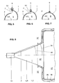
- FIGS. 5 to 7 show three partial cross sections of the double-cone part 26 in its transition region 28. The beginning of FIG. 5, the middle part in FIG. 6 and the end of the transition region 28 in FIG. 7 are shown. In the transition region 28, the diameter of the fuel line 9 and of the openings 12 in the flow direction 3 is reduced. At the end of the transition area 28, the air inlet slots 7, 8 and the openings 12 are completely closed. Neither air inlet slots 7, 8 nor fuel lines 9, 10 are arranged on the circular outlet diffuser 27 that adjoins downstream (FIG. 3).
- the arrangement of the outlet diffuser 27 additionally provides time and space for the mixing in of the gaseous fuel 11 which is only introduced in the downstream region of the double-cone part 26. In this way, an optimal fuel concentration is achieved across the cross-section of the burner. When burning such a homogenized fuel mixture, the NOx and CO emissions are significantly reduced. A reduction in emissions is also achieved when using liquid fuel 21, but the advantage in this case is not that great.
- the flow of the fuel mixture is slightly delayed in the outlet diffuser 27 and is therefore unstable at its center.
- the central backflow zone 24 of the fuel mixture is formed and the conical fuel profile 22 bursts only in the vicinity of the downstream end of the outlet diffuser 27 reached in the combustion chamber 17.
- the boundary layer in its interior does not detach, so that a stable flame front 25 can advantageously only be formed downstream of the double-cone burner.
- the outlet diffuser 27 has an opening angle 34, which is formed equal to the cone angle 16 of the burner (FIG. 8). Due to the simple, straight shape of the outlet diffuser 27, this double-cone burner can be manufactured much lighter and cheaper.
- a cooling air baffle is outside the combustion chamber wall 35 36 arranged, which extends upstream to the outlet diffuser 27 and ends at the downstream end of the air inlet slots 7, 8.
- the outlet diffuser 27 is cooled from the outside with cooling air flowing back in the space between the combustion chamber wall 35 and the cooling air baffle 36, the latter finally opening into a plenum 37 formed upstream of the burner. Because of this convective cooling of the outlet diffuser 27, the operational safety is further improved compared to the first exemplary embodiment.
Abstract
Description
Die Erfindung betrifft einen Kegelbrenner für gasförmige und/oder flüssige Brennstoffe, gemäss dem Oberbegriff des Anspruchs 1.The invention relates to a cone burner for gaseous and / or liquid fuels, according to the preamble of
Aus dem EP-B1-0321809 ist ein für die Verbrennung gasförmiger und/oder flüssiger Brennstoffe geeigneter Doppelkegelbrenner bekannt. Dieser Brenner bestehet aus zwei hohlen, sich zu einem Körper ergänzenden Teilkegelkörpern, welche tangentiale Lufteintrittschlitze aufweisen. Am radialen Ende jedes Lufteintrittschlitzes ist eine Leitung für gasförmigen Brennstoff angeordnet. Das Zumischen des gasförmigen Brennstoffs in die tangential einströmende Verbrennungsluft erfolgt daher innerhalb der Lufteintrittschlitze, und zwar im gesamten Innenraum des Brenners. Bei Verwendung von flüssigem Brennstoff wird dieser über eine zentral angeordnete Düse in den Brennerinnenraum eingedüst.EP-B1-0321809 discloses a double-cone burner suitable for the combustion of gaseous and / or liquid fuels. This burner consists of two hollow partial cone bodies that complement one another and have tangential air inlet slots. A line for gaseous fuel is arranged at the radial end of each air inlet slot. The gaseous fuel is therefore mixed into the tangentially flowing combustion air within the air inlet slots, specifically in the entire interior of the burner. If liquid fuel is used, it is injected into the burner interior via a centrally arranged nozzle.
Am Brennerende eines solchen Doppelkegelbrenners kommt es zur Ausbildung einer zentralen Rückströmzone des Brenngemisches. In diesem Bereich ist bereits ein im zeitlichen Mittel homogenes Brennstoffprofil über den Brennerquerschnitt erreicht. Die Zündung des Brenngemisches erfolgt an der Spitze der Rückströmzone, so dass dort eine stabile Flammenfront entsteht. Durch die plötzliche Flächenerweiterung zur Brennkammer bildet sich zudem auch ein äusseres Rezirkulationsgebiet, welches ebenfalls zur Flammenstabilisierung beiträgt.At the burner end of such a double-cone burner, a central backflow zone of the combustion mixture is formed. In this area, an average fuel profile over the burner cross-section has already been achieved on average. The combustion mixture is ignited at the top of the return flow zone, so that a stable flame front is created there. The sudden expansion of the area to the combustion chamber also creates an outer recirculation area, which also contributes to flame stabilization.
Bei Verwendung von flüssigem Brennstoff wird die Brennstoffkonzentration durch die tangential eingeleitete Verbrennungsluft in axialer Richtung abgebaut, so dass ein gut vorgemischtes Brenngemisch entsteht. Wird jedoch gasförmiger Brennstoff eingesetzt, so ist der Abstand zumindest von den im stromabwärtigen Bereich des Brenners angeordneten Einmischstellen des Brennstoffes bis zur Flamme nur sehr gering. Deshalb führt das dort vorliegende, zeitlich und örtlich noch nicht vollständig homogenisierte Brenngemisch zu einer erhöhten Produktion von Stickoxiden und von Kohlenmonoxid.When using liquid fuel, the fuel concentration is reduced in the axial direction by the tangentially introduced combustion air, so that a well-premixed fuel mixture is created. However, if gaseous fuel is used, the distance from the mixing points of the fuel arranged in the downstream region of the burner to the flame is only very small. For this reason, the fuel mixture present there, which has not yet been completely homogenized in terms of time and location, leads to increased production of nitrogen oxides and carbon monoxide.
Die Erfindung versucht, alle diese Nachteile zu vermeiden. Ihr liegt die Aufgabe zugrunde, einen Kegelbrenner für gasförmige und/oder flüssige Brennstoffe zu schaffen, der eine verringerte NOx- und CO-Emission aufweist.The invention tries to avoid all of these disadvantages. It is based on the task of creating a cone burner for gaseous and / or liquid fuels which has a reduced NOx and CO emission.
Erfindungsgemäss wird dies dadurch erreicht, dass bei einer Vorrichtung gemäss dem Oberbegriff des Anspruchs 1, die Teilkegelkörper an ihrem stromabwärtigen Ende einen gemeinsamen Auslassdiffusor besitzen. Die Teilkegelkörper weisen einen Übergangsbereich zum Auslassdiffusor auf, in dem die Grösse der Lufteintrittschlitze in Strömungsrichtung kontinuierlich abnimmt. Der Auslassdiffusor ist kreisrund und ohne Lufteintrittschlitze ausgebildet.This is achieved according to the invention in that in a device according to the preamble of
Aufgrund dieser Ausbildung des Kegelbrenners wird bei geeigneter Wahl der Schlitzweite das Wirbelaufplatzen und damit die Zündung des Brenngemisches weiter stromab, in die Nähe des Auslassdiffusorendes verlagert. Dadurch wird die am Brennerende zur Verfügung stehende Mischstrecke und Mischzeit wesentlich verlängert. Somit entsteht ein besser homogenisiertes Brenngemisch, was zu einer deutlichen Verringerung der NOx- und der CO-Emissionen führt. Dies betrifft sowohl den Einsatz von flüssigem als auch von gasförmigem Brennstoff, wobei der Vorteil bei letzterem bedeutend grösser ist. Mit der kontinuierlichen Verringerung der Grösse der Lufteintrittschlitze werden plötzliche Querschnittsprünge im Übergangsbereich von der Kegelbrennergeometrie zum kreisrunden Auslassdiffusor verhindert. Auf diese Weise lassen sich Ablösegebiete der Strömung des Frisch-Brenngemisches und somit eine dort unerwünschte Flammenhaltung vermeiden. Der Kegelbrenner weist nunmehr einen kreisförmigen Austrittsquerschnitt zum Brennraum auf, womit gegenüber den bekannten-Doppelkegelbrennern der Kühlluftbedarf für die dort eingesetzten Sicheln entfällt. Als zusätzlichen Vorteil bewirkt der Auslassdiffusor eine stärkere Abschirmung der Reaktionszone gegenüber den benachbarten Brennern, wodurch eine erhöhte Flammenstabilität erreicht wird.Due to this design of the cone burner, with a suitable choice of the slot width, the vortex bursting and thus the ignition of the fuel mixture is shifted further downstream into the vicinity of the outlet diffuser end. This significantly increases the mixing distance and mixing time available at the end of the burner. This creates a better homogenized fuel mixture, which leads to a significant reduction in NOx and CO emissions. This affects both Use of liquid as well as gaseous fuel, the advantage of the latter being significantly greater. With the continuous reduction in the size of the air inlet slots, sudden cross-sectional jumps in the transition area from the cone burner geometry to the circular outlet diffuser are prevented. In this way, detachment areas of the flow of the fresh fuel mixture and thus undesired flame retention can be avoided. The cone burner now has a circular outlet cross-section to the combustion chamber, which means that, compared to the known double-cone burners, there is no need for cooling air for the sickles used there. As an additional advantage, the outlet diffuser provides a stronger shielding of the reaction zone from the neighboring burners, which results in increased flame stability.
Es ist besonders zweckmässig, wenn im Übergangsbereich der Teilkegelkörper zum Auslassdiffusor der Durchmesser der Brennstoff zuführungen in Strömungsrichtung abnimmt. Damit wird die Gasbelochung im Übergangsbereich entsprechend der lokalen Schlitzweite angepasst und eine gleichmässige Verteilung des gasförmigen Brennstoffes in der Verbrennungsluft erreicht.It is particularly useful if the diameter of the fuel supply decreases in the direction of flow in the transition area of the partial cone body to the outlet diffuser. In this way, the gas perforation in the transition area is adjusted according to the local slot width and a uniform distribution of the gaseous fuel in the combustion air is achieved.
Ferner ist es vorteilhaft, wenn der Auslassdiffusor eine Länge von etwa 10 bis 25 Prozent der Gesamtlänge des Kegelbrenners aufweist und eine Austrittsfläche besitzt, welche nicht grösser als das 1,3-fache einer am Anfang des Übergangsbereiches ausgebildeten Querschnittsfläche des von den Teilkegelkörpern gebildeten Doppelkegelteils ist. Ein solcher, relativ kurzer Diffusor hat eine geringe Grenzschichtdicke zur Folge, so dass ein Rückschlagen der Flamme in der Grenzschicht verhindert wird.It is also advantageous if the outlet diffuser has a length of approximately 10 to 25 percent of the total length of the cone burner and has an outlet area which is not greater than 1.3 times a cross-sectional area of the double cone part formed by the partial cone bodies at the beginning of the transition region . Such a relatively short diffuser results in a small boundary layer thickness, so that the flame does not kick back in the boundary layer.
In einer zweiten Ausführungsform besitzt der Auslassdiffusor einen in Strömungsrichtung kontinuierlich zunehmenden Öffnungswinkel, der anfänglich gleich dem Kegelwinkel des Brenners und stromab kontinuierlich grösser als dieser ausgebildet ist. Dadurch wird die Wandgrenzschicht stabilisiert und so die Gefahr der Strömungsablösung minimiert.In a second embodiment, the outlet diffuser has an opening angle which increases continuously in the direction of flow and which initially corresponds to the cone angle of the burner and is continuously larger downstream than this. This stabilizes the wall boundary layer and minimizes the risk of flow separation.
In der Zeichnung sind zwei Ausführungsbeispiele der Erfindung anhand eines mit einer Brennkammer verbundenen Doppelkegelbrenners dargestellt.The drawing shows two exemplary embodiments of the invention using a double-cone burner connected to a combustion chamber.
Es zeigen:
- einen Doppelkegelbrenner des Standes der Technik, perspektivisch und entsprechend aufgeschnitten dargestellt;
- Fig. 2
- einen Schnitt II-II durch den in Fig. 1 gezeigten Brenner, schematisch vereinfacht dargestellt;
- Fig. 3
- eine schematische Darstellung eines erfindungsgemässen Doppelkegelbrenners in Seitenansicht;
- Fig. 4
- einen Ausschnitt von Fig. 3 mit vergrösserter Darstellung des Übergangsbereiches zum Auslassdiffusor;
- Fig. 5 bis Fig. 7
- Teilquerschnitte des Übergangsbereiches, entlang der Linien V-V, VI-VI, VII-VII in Fig. 4;
- Fig. 8
- eine Darstellung entsprechend Fig. 3, jedoch in einer anderen Ausführungsform.
- a double-cone burner of the prior art, shown in perspective and cut accordingly;
- Fig. 2
- a section II-II through the burner shown in Figure 1, shown schematically simplified.
- Fig. 3
- a schematic representation of a double-cone burner according to the invention in side view;
- Fig. 4
- a detail of Figure 3 with an enlarged view of the transition area to the outlet diffuser.
- 5 to 7
- Partial cross sections of the transition area, along the lines VV, VI-VI, VII-VII in Fig. 4;
- Fig. 8
- a representation corresponding to FIG. 3, but in another embodiment.
Es sind nur die für das Verständnis der Erfindung wesentlichen Elemente gezeigt. Die Strömungsrichtung der Arbeitsmittel ist mit Pfeilen bezeichnet.Only the elements essential for understanding the invention are shown. The direction of flow of the work equipment is indicated by arrows.
In der Figur 1 ist ein aus dem Stand der Technik bekannter Doppelkegelbrenner dargestellt. Er besteht aus zwei halben, hohlen Teilkegelkörpern 1, 2, die seitlich versetzt zueinander, aufeinander liegen und sich zu einem Körper ergänzen. Daher besitzen die Teilkegelkörper 1, 2 in Strömungsrichtung 3 versetzt zueinander angeordnete Mittelachsen 4, 5 (Fig. 2). Der Doppelkegelbrenner weist einen sich in Strömungsrichtung 3 kegelförmig erweiternden Brennerinnenraum 6 auf. Zwischen den Teilkegelkörpern 1, 2 sind tangentiale Lufteintrittschlitze 7, 8 ausgebildet.1 shows a double-cone burner known from the prior art. It consists of two halves, hollow
An beiden Teilkegelkörpern 1, 2 und dort am äusseren Ende der Lufteintrittschlitze 7, 8 ist jeweils eine Brennstoffleitung 9, 10 für gasförmigen Brennstoff 11 angeordnet (Fig. 1). Die Brennstoffleitungen 9, 10 sind mit mehreren, im gesamten Bereich der Lufteintrittschlitze 7, 8 gleichmässig verteilten und als Öffnungen ausgebildeten Brennstoff zuführungen 12 versehen. Beide Teilkegelkörper 1, 2 besitzen jeweils einen zylindrischen Anfangsteil 13, 14, welche ebenfalls versetzt zueinander angeordnet sind. Somit sind die tangentialen Lufteintrittschlitze 7, 8 anströmseitig über die gesamte Länge des Doppelkegelbrenners ausgebildet. Am stromaufwärtigen Ende des Doppelkegelbrenners, d.h. in dessen zylindrischem Anfangsteil 13, 14, ist eine in den Brennerinnenraum 6 mündende, zentralen Flüssigbrennstoffdüse 15 angeordnet. Beide Teilkegelkörper 1, 2 weisen einen flachen, im Bereich von 10° bis 30° ausgebildeten Kegelwinkel 16 auf. Brennkammerseitig 17 ist am Doppelkegelbrenner eine kragenförmige, als Verankerung für die Teilkegelkörper 1, 2 dienende Abschlussplatte 18 angeordnet. In der Abschlussplatte 18 ist eine Anzahl von Bohrungen 19 ausgebildet, durch welche Kühlluft 20 für die unmittelbar stromauf der Abschlussplatte 18 befindlichen, sichelförmigen Enden der Teilkegelkörper 1, 2 zur Brennkammer 17 abgeleitet wird.A
Bei Verwendung von flüssigem Brennstoff 21 erfolgt dessen Eindüsung in einem spitzen Winkel, am engsten Querschnitt des Brennerinnenraumes 6. Dadurch bildet sich ein kegeliges Brennstoffprofil 22 aus, welches von über die tangentialen Lufteintrittschlitze 7, 8 einströmender, rotierender Verbrennungsluft 23 umschlossen wird. In axialer Richtung wird die Konzentration des flüssigen Brennstoffes 21 fortlaufend durch die eingemischte Verbrennungsluft 23 abgebaut. Am stromabwärtigen Ende des Doppelkegelbrenners kommt es zur Ausbildung einer zentralen Rückströmzone 24 des Brenngemisches, welches das kegelige Brennstoffprofil 22 zum Aufplatzen (Vortex-Breakdown) bringt. Dadurch wird in diesem Bereich eine gute Brennstoffkonzentration über den Brennerquerschnitt erreicht. Die Zündung des Brenngemisches erfolgt an der Spitze der Rückströmzone 24. Erst an dieser Stelle kann eine stabile Flammenfront 25 entstehen.
Wird gasförmiger Brennstoff 11 verbrannt, gelangt dieser durch die Öffnungen 12 in den Brennerinnenraum 6, wobei er der Verbrennungsluft 23 zugemischt wird. Dabei bildet sich im Brennerinnenraum 6 ebenfalls ein kegeliges Brennstoffprofil 22 aus.When using
If
Die Fig. 3 zeigt eine schematische Darstellung eines erfindungsgemässen Doppelkegelbrenners. Aus Gründen der Übersichtlichkeit sind nur die wesentlichen Bauteile bzw. die gegenüber dem in Fig. 1 und 2 aufgezeigten Stand der Technik veränderten Bauteile dargestellt.3 shows a schematic representation of a double-cone burner according to the invention. For the sake of clarity, only the essential components or the components which have been changed compared to the prior art shown in FIGS. 1 and 2 are shown.
Die beiden halben, hohlen Teilkegelkörper 1, 2 des Brenners ergänzen sich zu einem als Doppelkegelteil ausgebildeten Körper 26, welcher stromab in einen gemeinsamen, kreisrunden Auslassdiffusor 27 übergeht. Unmittelbar stromauf des Auslassdiffusors 27 ist ein Übergangsbereich 28 vom Doppelkegelteil 26 zum Auslassdiffusor 27 ausgebildet. In diesem Übergangsbereich 28 nimmt die Grösse der Lufteintrittschlitze 7, 8 in Strömungsrichtung 3 kontinuierlich ab. Dabei wird jedoch der Brennerquerschnitt kontinuierlich erweitert, wodurch die vom Brenngemisch durchströmte Fläche auch im Übergangsbereich 28 grösser wird oder zumindest konstant bleibt.The two half, hollow
Der Auslassdiffusor 27 weist eine Länge 29 von etwa 15 Prozent der Gesamtlänge 30 des Doppelkelbrenners auf. Seine Austrittsfläche 31 entspricht etwa dem 1,3-fachen der Querschnittsfläche 32 am Anfang des Übergangsbereiches 28. Er besitzt einen Öffnungswinkel 33, der zunächst gleich dem Kegelwinkel 16 des Brenners ist und in Strömungsrichtung 3 kontinuierlich zunimmt.The
In Figur 4 ist der Übergangsbereich 28 zum Auslassdiffusor 27 vergrössert dargestellt, wodurch Anordnung und Ausbildung der am stromabwärtigen Ende des Übergangsbereichs 28 endenden Brennstoffleitung 9 deutlich werden.The
Die Figuren 5 bis 7 zeigen drei Teilquerschnitte des Doppelkegelteils 26 in seinem Übergangsbereich 28. In Fig. 5 ist der Beginn, in Fig. 6 der Mittelteil und in Fig. 7 das Ende des Übergangsbereiches 28 dargestellt. Im Übergangsbereich 28 wird der Durchmesser der Brennstoffleitung 9 sowie der Öffnungen 12 in Strömungsrichtung 3 reduziert. Bereits am Ende des Übergangsbereiches 28 sind die Lufteintrittschlitze 7, 8 und die Öffnungen 12 vollständig verschlossen. Am sich stromabwärts anschliessenden, kreisrunden Auslassdiffusor 27 sind weder Lufteintrittschlitze 7, 8 noch Brennstoffleitungen 9, 10 angeordnet (Fig. 3).FIGS. 5 to 7 show three partial cross sections of the double-
Im Unterschied zur bereits oben beschriebenen Funktion eines bekannten Doppelkegelbrenners wird durch die Anordnung des Auslassdiffusors 27 zusätzlich Zeit und Raum für die Einmischung auch des erst im stromabwärtigen Bereich des Doppelkegelteils 26 eingeführten, gasförmigen Brennstoffes 11 gewonnen. Auf diese Weise wird eine optimale Brennstoffkonzentration über den Brennerquerschnitt erreicht. Bei Verbrennung eines solchen, homogenisierten Brenngemisches werden die NOx- und die CO-Emissionen deutlich gesenkt. Auch bei Verwendung von flüssigem Brennstoff 21 wird eine Verringerung der Emissionen erreicht, jedoch ist der Vorteil in diesem Fall nicht so gross.In contrast to the function of a known double-cone burner already described above, the arrangement of the
Im Auslassdiffusor 27 wird die Strömung des Brenngemisches leicht verzögert und somit in ihrem Zentrum instabil. Dadurch kommt es erst in die Nähe des stromabwärtigen Endes des Auslassdiffusors 27 zur Ausbildung der zentralen Rückströmzone 24 des Brenngemisches und somit zum Aufplatzen des kegeligen Brennstoffprofils 22. Weil der Auslassdiffusor 27 trompetenförmig ausgebildet ist, wird ein stetiger Oberflächenverlauf vom Übergangsbereich 28 bis zum Eintritt des Brenngemisches in die Brennkammer 17 erreicht. Demzufolge löst die Grenzschicht in seinem Inneren nicht ab, so dass sich vorteilhaft erst stromab des Doppelkegelbrenners eine stabile Flammenfront 25 ausbilden kann. Durch Veränderung der Länge des Doppelkegelteils 26, der Schlitzweite, des Öffnungswinkels 32 oder der Anzahl der Lufteintrittschlitze 7, 8 kann der Ort des Wirbelaufplatzens entsprechend der konkreten Bedingungen beeinflusst werden.The flow of the fuel mixture is slightly delayed in the
Wegen der im Übergangsbereich 28 vom Doppelkegelteil 26 zum Auslassdiffusor 27 kontinuierlich verringerten Grösse der Lufteintrittschlitze 7, 8 wird ein strömungsgünstiger Übergang von der Doppelkegelbrenner-Geometrie zum kreisrunden Auslassdiffusor 27 erreicht. Damit werden plötzliche Querschnittsprünge vermieden. Die Anpassung der Gasbelochung an die lokale Grösse der Lufteintrittschlitze 7, 8 erfolgt durch die entsprechende Verringerung der Öffnungsdurchmesser. Natürlich kann auch der Abstand zwischen den Öffnungen 12 erhöht werden. Ein zusätzlicher Vorteil des trompetenförmig ausgebildeten Auslassdiffusors 27 ist die stabilisierende Wirkung seiner konvex gekrümmten Wand.Because of the continuously reduced size of the
In einem zweiten Ausführungsbeispiel besitzt der Auslassdiffusor 27 einen Öffnungswinkel 34, der gleich dem Kegelwinkel 16 des Brenners ausgebildet ist (Fig. 8). Aufgrund der einfachen, geraden Form des Auslassdiffusors 27 kann dieser Doppelkegelbrenner wesentlich leichter und billiger gefertigt werden. Zudem ist ausserhalb der Brennkammerwand 35 ein Kühlluftleitblech 36 angeordnet, welches stromauf bis zum Auslassdiffusor 27 reicht und am stromabwärtigen Ende der Lufteintrittschlitze 7, 8 endet. Der Auslassdiffusor 27 wird mit im Raum zwischen Brennkammerwand 35 und Kühlluftleitblech 36 zurückströmender Kühlluft von aussen gekühlt, wobei letztere schliesslich in ein stromauf des Brenners ausgebildetes Plenum 37 mündet. Aufgrund dieser konvektiven Kühlung des Auslassdiffusors 27 wird die Betriebssicherheit gegenüber dem ersten Ausführungsbeispiel weiter verbessert.In a second exemplary embodiment, the
- 11
- TeilkegelkörperPartial cone body
- 22nd
- TeilkegelkörperPartial cone body
- 33rd
- StrömungsrichtungFlow direction
- 44th
- MittelachseCentral axis
- 55
- MittelachseCentral axis
- 66
- BrennerinnenraumBurner interior
- 77
- LufteintrittschlitzAir inlet slot
- 88th
- LufteintrittschlitzAir inlet slot
- 99
- BrennstoffleitungFuel line
- 1010th
- BrennstoffleitungFuel line
- 1111
- gasförmiger Brennstoffgaseous fuel
- 1212th
- Brennstoffzuführung, ÖffnungFuel supply, opening
- 1313
- AnfangsteilInitial part
- 1414
- AnfangsteilInitial part
- 1515
- FlüssigbrennstoffdüseLiquid fuel nozzle
- 1616
- KegelwinkelCone angle
- 1717th
- BrennkammerCombustion chamber
- 1818th
- AbschlussplatteEnd plate
- 1919th
- Bohrungdrilling
- 2020th
- KühlluftCooling air
- 2121
- flüssiger Brennstoffliquid fuel
- 2222
- kegeliges Brennstoffprofiltapered fuel profile
- 2323
- VerbrennungsluftCombustion air
- 2424th
- RückströmzoneBackflow zone
- 2525th
- FlammenfrontFlame front
- 2626
- Körper, DoppelkegelteilBody, double cone part
- 2727
- AuslassdiffusorOutlet diffuser
- 2828
- ÜbergangsbereichTransition area
- 2929
- Länge von 27Length of 27
- 3030th
- Gesamtlänge von 26 und 27Total length of 26 and 27
- 3131
- Austrittsfläche von 27Exit area of 27
- 3232
- QuerschnittsflächeCross sectional area
- 3333
- Öffnungswinkel von 27Opening angle of 27
- 3434
- Öffnungswinkel von 27Opening angle of 27
- 3535
- BrennkammerwandCombustion chamber wall
- 3636
- KühlluftleitblechCooling air baffle
- 3737
- Plenumplenum
Claims (5)
Applications Claiming Priority (2)
| Application Number | Priority Date | Filing Date | Title |
|---|---|---|---|
| DE19548853 | 1995-12-27 | ||
| DE19548853A DE19548853A1 (en) | 1995-12-27 | 1995-12-27 | Cone burner |
Publications (3)
| Publication Number | Publication Date |
|---|---|
| EP0783089A2 true EP0783089A2 (en) | 1997-07-09 |
| EP0783089A3 EP0783089A3 (en) | 1998-11-11 |
| EP0783089B1 EP0783089B1 (en) | 2001-04-11 |
Family
ID=7781504
Family Applications (1)
| Application Number | Title | Priority Date | Filing Date |
|---|---|---|---|
| EP96810821A Expired - Lifetime EP0783089B1 (en) | 1995-12-27 | 1996-11-25 | Cone-shaped burner |
Country Status (5)
| Country | Link |
|---|---|
| US (1) | US5807097A (en) |
| EP (1) | EP0783089B1 (en) |
| JP (1) | JP3810502B2 (en) |
| CN (1) | CN1119560C (en) |
| DE (2) | DE19548853A1 (en) |
Cited By (2)
| Publication number | Priority date | Publication date | Assignee | Title |
|---|---|---|---|---|
| WO2013144048A1 (en) * | 2012-03-29 | 2013-10-03 | Alstom Technology Ltd | Gas turbine combustor |
| EP2722592A1 (en) * | 2012-10-22 | 2014-04-23 | Alstom Technology Ltd | Multiple cone gas turbine burner |
Families Citing this family (11)
| Publication number | Priority date | Publication date | Assignee | Title |
|---|---|---|---|---|
| EP0924458B1 (en) * | 1997-12-22 | 2002-08-28 | Alstom | Burner |
| DE50110801D1 (en) * | 2000-12-23 | 2006-10-05 | Alstom Technology Ltd | Burner for generating a hot gas |
| DE10342763A1 (en) * | 2003-09-16 | 2005-07-07 | BSH Bosch und Siemens Hausgeräte GmbH | Gas burner for liquid fuel |
| FR2870741B1 (en) * | 2004-05-25 | 2008-03-14 | Coletica Sa | HYDRATED LAMELLAR OR LIPOSOME PHASE CONTAINING A FATTY MONOAMINE OR A CATIONIC POLYMER PROMOTING INTERCELLULAR PENETRATION AND A COSMETIC OR PHARMACEUTICAL COMPOSITION CONTAINING THE SAME. |
| EP1817526B1 (en) * | 2004-11-30 | 2019-03-20 | Ansaldo Energia Switzerland AG | Method and device for burning hydrogen in a premix burner |
| FR2915989B1 (en) * | 2007-05-10 | 2011-05-20 | Saint Gobain Emballage | LOW NOX MIXED INJECTOR |
| CN101852443B (en) * | 2010-03-15 | 2012-04-18 | 高海华 | Biomass boiler oxygenation strong-fire burnout device |
| US8967985B2 (en) | 2012-11-13 | 2015-03-03 | Roper Pump Company | Metal disk stacked stator with circular rigid support rings |
| CN104566371A (en) * | 2014-12-15 | 2015-04-29 | 昆山富凌能源利用有限公司 | Environment-friendly and energy-saving type gas stove core |
| KR101990767B1 (en) * | 2017-08-09 | 2019-06-20 | 한국기계연구원 | Double-cone gas turbine burner and method for providing air to the burner |
| CN109737450B (en) * | 2018-12-11 | 2019-12-03 | 北京航空航天大学 | Combustion chambers burn oscillation control device and combustion chambers burn oscillation control method |
Citations (1)
| Publication number | Priority date | Publication date | Assignee | Title |
|---|---|---|---|---|
| EP0321809B1 (en) | 1987-12-21 | 1991-05-15 | BBC Brown Boveri AG | Process for combustion of liquid fuel in a burner |
Family Cites Families (5)
| Publication number | Priority date | Publication date | Assignee | Title |
|---|---|---|---|---|
| DE3707773C2 (en) * | 1987-03-11 | 1996-09-05 | Bbc Brown Boveri & Cie | Process heat generation facility |
| CH679692A5 (en) * | 1989-04-24 | 1992-03-31 | Asea Brown Boveri | |
| EP0481111B1 (en) * | 1990-10-17 | 1995-06-28 | Asea Brown Boveri Ag | Gas-turbine combustion chamber |
| DE4316474A1 (en) * | 1993-05-17 | 1994-11-24 | Abb Management Ag | Premix burner for operating an internal combustion engine, a combustion chamber of a gas turbine group or a combustion system |
| DE4426353A1 (en) * | 1994-07-25 | 1996-02-01 | Abb Research Ltd | burner |
-
1995
- 1995-12-27 DE DE19548853A patent/DE19548853A1/en not_active Withdrawn
-
1996
- 1996-11-25 DE DE59606762T patent/DE59606762D1/en not_active Expired - Lifetime
- 1996-11-25 EP EP96810821A patent/EP0783089B1/en not_active Expired - Lifetime
- 1996-12-04 US US08/760,688 patent/US5807097A/en not_active Expired - Fee Related
- 1996-12-27 CN CN96121396A patent/CN1119560C/en not_active Expired - Lifetime
- 1996-12-27 JP JP35030796A patent/JP3810502B2/en not_active Expired - Lifetime
Patent Citations (1)
| Publication number | Priority date | Publication date | Assignee | Title |
|---|---|---|---|---|
| EP0321809B1 (en) | 1987-12-21 | 1991-05-15 | BBC Brown Boveri AG | Process for combustion of liquid fuel in a burner |
Cited By (3)
| Publication number | Priority date | Publication date | Assignee | Title |
|---|---|---|---|---|
| WO2013144048A1 (en) * | 2012-03-29 | 2013-10-03 | Alstom Technology Ltd | Gas turbine combustor |
| EP2722592A1 (en) * | 2012-10-22 | 2014-04-23 | Alstom Technology Ltd | Multiple cone gas turbine burner |
| US9464810B2 (en) | 2012-10-22 | 2016-10-11 | General Electric Technology Gmbh | Burner including a swirl chamber with slots having different widths |
Also Published As
| Publication number | Publication date |
|---|---|
| DE19548853A1 (en) | 1997-07-03 |
| EP0783089A3 (en) | 1998-11-11 |
| CN1158397A (en) | 1997-09-03 |
| JP3810502B2 (en) | 2006-08-16 |
| US5807097A (en) | 1998-09-15 |
| JPH09189406A (en) | 1997-07-22 |
| EP0783089B1 (en) | 2001-04-11 |
| DE59606762D1 (en) | 2001-05-17 |
| CN1119560C (en) | 2003-08-27 |
Similar Documents
| Publication | Publication Date | Title |
|---|---|---|
| EP0918191B1 (en) | Burner for the operation of a heat generator | |
| DE3222347C2 (en) | ||
| EP0321809B1 (en) | Process for combustion of liquid fuel in a burner | |
| EP0675322B1 (en) | Premix burner | |
| EP0833105B1 (en) | Premix burner | |
| EP0777081B1 (en) | Premix burner | |
| DE19545310B4 (en) | premix | |
| EP0911583B1 (en) | Method of operating a premix burner | |
| DE4426351A1 (en) | Combustion chamber | |
| CH680467A5 (en) | ||
| EP0783089B1 (en) | Cone-shaped burner | |
| EP0778445B1 (en) | Premix burner | |
| DE19547912A1 (en) | Burners for a heat generator | |
| EP0718561A2 (en) | Combustor | |
| EP0394800B1 (en) | Premix burner for generating a hot gas | |
| DE4330083A1 (en) | Method of operating a premix burner | |
| EP0851172B1 (en) | Burner and method for operating a combustion chamber with a liquid and/or gaseous fuel | |
| EP0994300B1 (en) | Burner for operating a heat generator | |
| EP0742411B1 (en) | Air supply for a premix combustor | |
| DE4412315B4 (en) | Method and device for operating the combustion chamber of a gas turbine | |
| EP0777082A2 (en) | Premix burner | |
| EP0740108A2 (en) | Burner | |
| EP0730121A2 (en) | Premix burner | |
| EP0807787A2 (en) | Burner | |
| EP0866268B1 (en) | Method of operating a vortex stabilised burner and burner applying the method |
Legal Events
| Date | Code | Title | Description |
|---|---|---|---|
| PUAI | Public reference made under article 153(3) epc to a published international application that has entered the european phase |
Free format text: ORIGINAL CODE: 0009012 |
|
| AK | Designated contracting states |
Kind code of ref document: A2 Designated state(s): DE FR GB IT |
|
| PUAL | Search report despatched |
Free format text: ORIGINAL CODE: 0009013 |
|
| AK | Designated contracting states |
Kind code of ref document: A3 Designated state(s): DE FR GB IT |
|
| 17P | Request for examination filed |
Effective date: 19981022 |
|
| GRAG | Despatch of communication of intention to grant |
Free format text: ORIGINAL CODE: EPIDOS AGRA |
|
| 17Q | First examination report despatched |
Effective date: 20000515 |
|
| GRAG | Despatch of communication of intention to grant |
Free format text: ORIGINAL CODE: EPIDOS AGRA |
|
| GRAG | Despatch of communication of intention to grant |
Free format text: ORIGINAL CODE: EPIDOS AGRA |
|
| GRAH | Despatch of communication of intention to grant a patent |
Free format text: ORIGINAL CODE: EPIDOS IGRA |
|
| GRAH | Despatch of communication of intention to grant a patent |
Free format text: ORIGINAL CODE: EPIDOS IGRA |
|
| GRAA | (expected) grant |
Free format text: ORIGINAL CODE: 0009210 |
|
| AK | Designated contracting states |
Kind code of ref document: B1 Designated state(s): DE FR GB IT |
|
| REF | Corresponds to: |
Ref document number: 59606762 Country of ref document: DE Date of ref document: 20010517 |
|
| ITF | It: translation for a ep patent filed |
Owner name: DE DOMINICIS & MAYER S.R.L. |
|
| GBT | Gb: translation of ep patent filed (gb section 77(6)(a)/1977) |
Effective date: 20010615 |
|
| ET | Fr: translation filed | ||
| REG | Reference to a national code |
Ref country code: GB Ref legal event code: 732E |
|
| REG | Reference to a national code |
Ref country code: GB Ref legal event code: IF02 |
|
| PLBE | No opposition filed within time limit |
Free format text: ORIGINAL CODE: 0009261 |
|
| STAA | Information on the status of an ep patent application or granted ep patent |
Free format text: STATUS: NO OPPOSITION FILED WITHIN TIME LIMIT |
|
| 26N | No opposition filed | ||
| REG | Reference to a national code |
Ref country code: FR Ref legal event code: TP |
|
| REG | Reference to a national code |
Ref country code: GB Ref legal event code: 732E Free format text: REGISTERED BETWEEN 20120802 AND 20120808 |
|
| REG | Reference to a national code |
Ref country code: FR Ref legal event code: TP Owner name: ALSTOM TECHNOLOGY LTD., CH Effective date: 20120918 |
|
| REG | Reference to a national code |
Ref country code: DE Ref legal event code: R082 Ref document number: 59606762 Country of ref document: DE Representative=s name: ROESLER PATENTANWALTSKANZLEI, DE |
|
| REG | Reference to a national code |
Ref country code: DE Ref legal event code: R082 Ref document number: 59606762 Country of ref document: DE Representative=s name: RUEGER, BARTHELT & ABEL, DE Effective date: 20130508 Ref country code: DE Ref legal event code: R082 Ref document number: 59606762 Country of ref document: DE Representative=s name: ROESLER PATENTANWALTSKANZLEI, DE Effective date: 20130508 Ref country code: DE Ref legal event code: R081 Ref document number: 59606762 Country of ref document: DE Owner name: GENERAL ELECTRIC TECHNOLOGY GMBH, CH Free format text: FORMER OWNER: ALSTOM, PARIS, FR Effective date: 20130508 Ref country code: DE Ref legal event code: R081 Ref document number: 59606762 Country of ref document: DE Owner name: ALSTOM TECHNOLOGY LTD., CH Free format text: FORMER OWNER: ALSTOM, PARIS, FR Effective date: 20130508 |
|
| REG | Reference to a national code |
Ref country code: FR Ref legal event code: TP Owner name: ALSTOM (SWITZERLAND) LTD, CH Effective date: 20131003 |
|
| REG | Reference to a national code |
Ref country code: FR Ref legal event code: PLFP Year of fee payment: 20 |
|
| PGFP | Annual fee paid to national office [announced via postgrant information from national office to epo] |
Ref country code: GB Payment date: 20151118 Year of fee payment: 20 Ref country code: DE Payment date: 20151119 Year of fee payment: 20 Ref country code: IT Payment date: 20151125 Year of fee payment: 20 |
|
| PGFP | Annual fee paid to national office [announced via postgrant information from national office to epo] |
Ref country code: FR Payment date: 20151119 Year of fee payment: 20 |
|
| REG | Reference to a national code |
Ref country code: DE Ref legal event code: R082 Ref document number: 59606762 Country of ref document: DE Representative=s name: RUEGER ABEL PATENTANWAELTE PARTGMBB, DE Ref country code: DE Ref legal event code: R082 Ref document number: 59606762 Country of ref document: DE Representative=s name: RUEGER, BARTHELT & ABEL, DE |
|
| REG | Reference to a national code |
Ref country code: DE Ref legal event code: R082 Ref document number: 59606762 Country of ref document: DE Representative=s name: RUEGER, BARTHELT & ABEL, DE Ref country code: DE Ref legal event code: R081 Ref document number: 59606762 Country of ref document: DE Owner name: GENERAL ELECTRIC TECHNOLOGY GMBH, CH Free format text: FORMER OWNER: ALSTOM TECHNOLOGY LTD., BADEN, CH |
|
| REG | Reference to a national code |
Ref country code: DE Ref legal event code: R071 Ref document number: 59606762 Country of ref document: DE |
|
| REG | Reference to a national code |
Ref country code: GB Ref legal event code: PE20 Expiry date: 20161124 |
|
| PG25 | Lapsed in a contracting state [announced via postgrant information from national office to epo] |
Ref country code: GB Free format text: LAPSE BECAUSE OF EXPIRATION OF PROTECTION Effective date: 20161124 |