EP0782328A2 - Rasterausgabeabtastsystem mit mehreren Strahlen mit Polarisationsmultiplexierung - Google Patents
Rasterausgabeabtastsystem mit mehreren Strahlen mit Polarisationsmultiplexierung Download PDFInfo
- Publication number
- EP0782328A2 EP0782328A2 EP96309343A EP96309343A EP0782328A2 EP 0782328 A2 EP0782328 A2 EP 0782328A2 EP 96309343 A EP96309343 A EP 96309343A EP 96309343 A EP96309343 A EP 96309343A EP 0782328 A2 EP0782328 A2 EP 0782328A2
- Authority
- EP
- European Patent Office
- Prior art keywords
- laser
- onto
- laser beams
- optical
- beams
- Prior art date
- Legal status (The legal status is an assumption and is not a legal conclusion. Google has not performed a legal analysis and makes no representation as to the accuracy of the status listed.)
- Withdrawn
Links
- 230000010287 polarization Effects 0.000 title claims abstract description 106
- 230000003287 optical effect Effects 0.000 claims abstract description 109
- 108091008695 photoreceptors Proteins 0.000 claims abstract description 54
- 238000010408 sweeping Methods 0.000 claims description 7
- 230000004044 response Effects 0.000 claims description 6
- 239000004065 semiconductor Substances 0.000 description 19
- 238000007639 printing Methods 0.000 description 15
- 230000009977 dual effect Effects 0.000 description 9
- 230000001965 increasing effect Effects 0.000 description 9
- 238000000034 method Methods 0.000 description 9
- 230000005540 biological transmission Effects 0.000 description 8
- 230000001427 coherent effect Effects 0.000 description 7
- 230000005701 quantum confined stark effect Effects 0.000 description 7
- 230000002829 reductive effect Effects 0.000 description 7
- 230000007704 transition Effects 0.000 description 7
- 230000012010 growth Effects 0.000 description 6
- 239000000463 material Substances 0.000 description 6
- 238000010521 absorption reaction Methods 0.000 description 5
- 239000000203 mixture Substances 0.000 description 5
- 238000005253 cladding Methods 0.000 description 4
- 239000003086 colorant Substances 0.000 description 4
- 239000000758 substrate Substances 0.000 description 4
- 230000008901 benefit Effects 0.000 description 3
- 238000010276 construction Methods 0.000 description 3
- 238000012937 correction Methods 0.000 description 3
- 230000005684 electric field Effects 0.000 description 3
- 238000002955 isolation Methods 0.000 description 3
- 238000002310 reflectometry Methods 0.000 description 3
- 229910001218 Gallium arsenide Inorganic materials 0.000 description 2
- 238000013459 approach Methods 0.000 description 2
- 230000008859 change Effects 0.000 description 2
- 230000003111 delayed effect Effects 0.000 description 2
- 230000001419 dependent effect Effects 0.000 description 2
- 238000005516 engineering process Methods 0.000 description 2
- 230000005669 field effect Effects 0.000 description 2
- 239000002184 metal Substances 0.000 description 2
- 238000012986 modification Methods 0.000 description 2
- 230000004048 modification Effects 0.000 description 2
- 230000009467 reduction Effects 0.000 description 2
- 230000002441 reversible effect Effects 0.000 description 2
- 238000000926 separation method Methods 0.000 description 2
- 229910000980 Aluminium gallium arsenide Inorganic materials 0.000 description 1
- 230000005699 Stark effect Effects 0.000 description 1
- 229910000756 V alloy Inorganic materials 0.000 description 1
- 230000002745 absorbent Effects 0.000 description 1
- 239000002250 absorbent Substances 0.000 description 1
- 230000009471 action Effects 0.000 description 1
- 229910045601 alloy Inorganic materials 0.000 description 1
- 239000000956 alloy Substances 0.000 description 1
- 238000003491 array Methods 0.000 description 1
- 230000004888 barrier function Effects 0.000 description 1
- 238000005513 bias potential Methods 0.000 description 1
- 238000005229 chemical vapour deposition Methods 0.000 description 1
- 238000004140 cleaning Methods 0.000 description 1
- 230000003247 decreasing effect Effects 0.000 description 1
- 239000006185 dispersion Substances 0.000 description 1
- 230000000694 effects Effects 0.000 description 1
- 238000003384 imaging method Methods 0.000 description 1
- 230000001939 inductive effect Effects 0.000 description 1
- 230000000670 limiting effect Effects 0.000 description 1
- 230000007246 mechanism Effects 0.000 description 1
- 230000010355 oscillation Effects 0.000 description 1
- 230000036961 partial effect Effects 0.000 description 1
- 238000012545 processing Methods 0.000 description 1
- 230000005855 radiation Effects 0.000 description 1
- 238000001228 spectrum Methods 0.000 description 1
Images


Classifications
-
- H—ELECTRICITY
- H04—ELECTRIC COMMUNICATION TECHNIQUE
- H04N—PICTORIAL COMMUNICATION, e.g. TELEVISION
- H04N1/00—Scanning, transmission or reproduction of documents or the like, e.g. facsimile transmission; Details thereof
- H04N1/46—Colour picture communication systems
- H04N1/50—Picture reproducers
- H04N1/506—Reproducing the colour component signals picture-sequentially, e.g. with reproducing heads spaced apart from one another in the subscanning direction
Definitions
- This invention relates to a multiple beam raster output scanning system and, more particularly, to a multiple beam raster output scanning system with polarization multiplexing lasers.
- xerographic printing also called electrophotographic printing
- a latent image is formed on a charged photoreceptor, usually by raster sweeping a modulated laser beam across the photoreceptor.
- the latent image is then used to create a permanent image by transferring and fusing toner that was electrostatically attracted to the latent image onto a recording medium, usually plain paper.
- ROSs Raster Output Scanners
- Printers that sweep several beams simultaneously are referred to as multiple beam printers.
- a color xerographic printer requires a separate image for each color printed, hereinafter called a system color. While a dual color printer requires only two images, a full color printer typically requires four images, one for each of the three primary colors of cyan, magenta, yellow, and an additional one for black.
- Color prints are currently produced by sequentially transferring and fusing overlapped system colors onto a single recording medium which is passed multiple times, once for each system color, through the printer. Such printers are referred to as multiple pass printers.
- the printer is referred to as a multistation printer; if the stations use different positions on the same photoreceptor, the printer is referred to as a single station/multiposition printer.
- Multistation and single station/multi position printers have greater printed page output than a multipass printer operating at the same raster sweep speed.
- the commercial introduction of multistation and single station/multiposition printers has been delayed by 1) cost problems, at least partially related to the cost of multiple xerographic elements and the associated ROSs, and 2) image quality problems, at least partially related to the difficulty of producing spots on each photoreceptor and then subsequently registering (overlapping) the images on the photoreceptor(s).
- Proposed prior art multistation printers usually use individual ROSs (each comprised of separate polygon mirrors, lenses, and related optical components) for each station. Problems with such systems include the high cost of producing nearly identical multiple ROSs and the difficulty of registering the system colors.
- a partial solution to the problems of multistation xerographic systems with individual ROSs is a recording apparatus (printer) having multiple recording stations and multiple lens systems, but only one rotating polygon mirror.
- the cost of the system is relatively low.
- differences in the lenses and mirror surfaces could still cause problems with accurate registration of different latent images.
- Another approach to overcoming the problems of multistation printers having individual ROSs is spatially overlapping a plurality of beams using an optical beam combiner, deflecting the overlapped beams using a single polygon mirror, separating the deflected beams using an optical filter (and polarizers if more than two beams are used), and directing the separated beams onto associated photoreceptors.
- the advantage of overlapping the laser beams is a significant cost reduction since the ROS is shared.
- the use of optical beam combiners to overlap beams so that they have similar optical axes and similar sized spots is thought to be difficult, expensive, and time consuming.
- a raster output scanning system employs a rotating polygon mirror that simultaneously deflects a plurality of clustered, dissimilar wavelength laser beams having common optical axes and substantially common origins from common mirror surface areas.
- the clustered beams are subsequently separated by a plurality of optical filters and are then directed onto associated photoreceptors of a multistation printer.
- optical filters require the dissimilar beams to be separated by a sufficiently large wavelength. Typically a wavelength difference of about 50nm is required such as lasers emitting beams at 645nm, 695nm, 755nm, and 825nm.
- a raster output scanning system employs a rotating polygon mirror that simultaneously deflects a plurality of clustered, dissimilar wavelength, dissimilar polarization state laser beams having common optical axes and substantially common origins from common mirror surface areas.
- the clustered beams are subsequently separated by a plurality of optical and polarization filters and are then directed onto associated photoreceptors of a multistation printer.
- Methods for reducing the number of different lasers in a raster output scanning system required to address multiple stations can reduce the complexity of the laser source and the cost of the related scanning optics to separate and locate the beams on the stations.
- a raster output scanner comprising:- polarization multiplexing means for producing at least first and second coaxially overlapping, orthogonally polarized laser beams on a first optical path; means for sweeping the coaxially overlapping, orthogonally polarized laser beams onto a second optical path; and optical beam separating means disposed on the second optical path for separating and directing at least the first laser beam onto a third optical path and at least the second laser beam onto a fourth optical path.
- a polarization multiplexed laser emits two beams of the same wavelength but orthogonal polarization from a single laser source for use in a multiple beam raster output scanning system.
- the multiple beam raster output scanning is obtained from a single raster scanning system (ROS) with a rotating mirror, beneficially a polygon mirror, and a single set of scan optics for use in single or multiple station printers.
- a plurality of coaxially overlapping laser beams from the same laser source, but of dissimilar polarization states are deflected using a common mirror surface area and are subsequently separated by a plurality of optical polarized beam separators and optical dichroic beam separators.
- the separated laser beams are directed onto associated photoreceptors such that their optical path lengths from the source location to their respective photoreceptors are substantially the same.
- a dual laser array will emit four beams of dissimilar wavelengths and dissimilar polarization states.
- the separated laser beams are subsequently directed onto associated photoreceptive regions of a single station/multiposition printer, or onto associated photoreceptors of a multistation printer.
- Similarly dimensioned and registered spots are readily obtained on all photoreceptive regions, beneficially by establishing a substantially similar optical path length for each laser beam.
- a raster output scanner comprising: polarization multiplexing means for producing overlapping and coaxial first, second, third, and fourth laser beams, wherein the first and second laser beams have differing wavelengths but similar polarizations, and wherein the third and fourth laser beams have differing wavelengths but similar polarizations, and wherein the polarizations of the first laser beam and the fourth laser beam differ; means for directing the first, second, third, and fourth laser beams onto a first optical path; means for sweeping the first, second, third and fourth laser beams along a second optical path; an optical polarized beam separator disposed on the second optical path, the optical polarized beam separator for directing the first and second laser beams onto a third optical path and for directing the third and fourth laser beam onto a fourth optical path; a first dichroic beam separator disposed on the third optical path, the first dichroic beam separator for directing the first laser beam onto a fifth optical path and
- a raster output scanner comprising: polarization multiplexing means for producing overlapping and coaxial first, second, third, and fourth laser beams, wherein the first and second laser beams have similar wavelengths but differing polarizations, and wherein the third and fourth laser beams have similar wavelengths but differing polarizations, and wherein the wavelengths of laser beams one and three differ; means for directing the first, second, third, and fourth laser beams onto a first optical path; means for sweeping the first, second, third and fourth laser beams along a second optical path; a dichroic beam separator disposed on the second optical path, the dichroic beam separator for directing the first and second laser beams onto a third optical path and for directing the third and fourth laser beams onto a fourth optical path; a first optical polarized beam separator disposed on the third optical path, the first optical polarized beam separator for directing the first laser beam onto a fifth optical path and for directing
- a single laser diode can be used to produce two different polarized beams of nominally the same wavelength which are easily separated based on their orthogonal polarization.
- the light beam output from a polarization multiplexed laser diode can be modulated rapidly enough so that the diode emission could contain two separate data streams, one encoded in the TE-polarized beam and one encoded in the TM-polarized beam. Because of the orthogonal polarization fields associated with the two beams, a raster output scanning system could easily distinguish between the TE and TM beams to separate and locate the beams on different printing stations. Since two beams will be emitted from one laser source, the number of different lasers required in a multiple station/position printing system is reduced by half.
- Quantum well (QW) lasers normally emit coherent light in the transverse electric (TE) polarization rather than the transverse magnetic (TM) polarization.
- TE transverse electric
- TM transverse magnetic
- the TE-mode gain arises from the heavy hole transition, while the TM-mode gain is provided by the light hole transitions.
- Quantum well (QW) lasers can however emit coherent light in the transverse electric (TE) or in the transverse magnetic (TM) mode.
- Quantum well (QW) lasers can switch from emitting coherent light in the TE-polarization mode to the TM-polarization mode, or vice versa. This ability to emit coherent light in either the TE- or TM-polarization states is accomplished in certain semiconductor material laser structures by controlling the type of strain induced in the epitaxially deposited active region due to lattice mismatches with the substrate.
- TM-polarization gain will predominate.
- the polarization of the emission can be determined by threshold carrier density and other factors, such as temperature, facet reflectivity, cavity length and intracavity optical loss.
- TM-polarization can be obtained by subjecting the active layer to biaxial tension, parallel to the plane of the junction of the active layer and the cladding layers.
- the desired polarization mode laser emitter can be achieved with either a single quantum well, carefully adjusted, or separate quantum wells for TE- and TM-mode gain with the polarization mode of laser oscillation dependent upon the modal gain characteristics and the threshold gain.
- the necessary gain characteristic has one polarization with lowest transparency current, and the orthogonal polarization with a greater peak gain.
- the polarization of each device can be selected, for example, by introducing an additional loss into one of the devices, thereby forcing it to emit coherent light in the higher-gain polarization.
- the polarization of each device could be switched, by using an intracavity loss modulator.
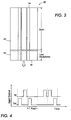
- Modal gain is plotted as a function of device current, for both the TM- and TE-modes.
- the modal gain, g, for both TM- and TE-modes is plotted vertically along the y coordinate, and current, I, for both modes is plotted horizontally along the x coordinate.
- the curve 10 labeled TE shows the gain characteristic for the TE-mode
- the curve 11 labeled TM shows the gain characteristic for the TM-mode.
- the quantum well when caused to lase at the lower threshold current 13 will emit TE-polarized radiation because the TE gain is higher for that current.
- a quantum well laser will lase in the TM-mode because the TM gain is higher for that current as indicated by line 15.
- the semiconductor laser structure 20 has a GaAs substrate 22 on which is epitaxially deposited, in a known manner, a succession of semiconductor layers comprising, in order, an (Al x Ga 1-x ) 0.5 In 0.5 P (0.6 ⁇ x clad ⁇ 1.0) N-cladding layer 24, an (Al x Ga 1-x ) 0.5 In 0.5 P (0.2 ⁇ x SCH ⁇ 0.6) lower N-confinement layer 26, a Ga z In 1-z P quantum well 28, an (Al x Ga 1-x ) 0.5 In 0.5 P (0.2 ⁇ x SCH ⁇ 0.6) upper P-confinement layer 30, an (Al x Ga 1-x ) 0.5 In 0.5 P (0.6 ⁇ x clad ⁇ 1.0) P-cladding layer 32, a Ga z In 1-z P (0.5 ⁇ z ES ⁇ 0.7) etch stop layer 34, an (Al x Ga 1-x ) 0.5 In 0.5 P (0.6 ⁇ x clad ⁇ 1.0) P-cladding layer 32, a
- a p-ohmic metal electrode 44 is formed on the cap layer 40 and a n-ohmic contact metal electrode 46 is formed on the substrate 22. Not shown are the usual reflecting facets forming the optical cavity with and perpendicular to the quantum well active layer 28 at opposite ends of the laser structure 20.
- a TE-mode/TM-mode switchable device can be made roughly similar.
- the polarization of the laser emission will be determined by the threshold gain, and the gain-current relationship for each mode as described in connection with Figure 1.
- the gain-current relationship must have certain characteristics. As shown in Figure 1, the transparency current must be lowest in one polarization, curve 10, while the peak gain is greatest in the orthogonal polarization, curve 11. Therefore, one polarization, TE, has a lower threshold current, while the other (higher gain) polarization, TM, only oscillates if the threshold gain is increased. This can be achieved, for example, by including an intracavity loss modulator section in the device, as shown schematically in Figure 3.
- Figure 3 schematically illustrates a top view of a laser structure 50 with an elongated active section 52 coupled to a modulator section 54.
- the lasing beam oscillates vertically between a reflecting face 56 at the top end and another reflecting facet 58 at the bottom end. Biasing means for the modulator section are not shown.
- Such a modulator section 54 is lossy when unpumped or biased below transparency, increasing the threshold gain enough that the high-gain polarization oscillates.
- the modulator is biased above transparency, the low-threshold polarization oscillates.
- the Figure 3 embodiment schematically illustrates a laser 50 with switchable polarization modes.
- a layer structure capable of either TE- or TM-mode emission can also include separate quantum wells for TE and TM mode gain.
- One QW will be tensile-strained providing TM-mode gain while the QW is compressed or lattice matched providing TE-mode gain.
- the transition wavelength must be well-matched for both QWs.
- the polarization will depend on the gain and loss characteristics.
- the quantum wells can be adjusted so that one polarization has a lower transparency current, while the other has a higher gain. Therefore, the lowest threshold polarization emits coherent light when the loss is low, and the high gain (and higher threshold) polarization dominates when an additional loss is introduced.
- the two-QW laser structure is similar to that of Figures 2 and 3, except that the second quantum well layer for TE-mode is added.
- the present invention is not limited to achieving TE- and TM-mode QW lasers in the same monolithic structure by varying the thickness and/or composition of the active quantum well layer. If an active layer is in near degeneracy at the band edge, then whether the laser will oscillate in the TE- or TM-mode will depend upon other factors, such as, the diode geometry, its threshold current, its reflectivity, temperature, cavity length, etc. Hence, in accordance with this aspect of the invention, the active layer is given the same composition and thickness, preferably lying on the crossover point.
- the polarization is determined by the threshold gain. If the threshold gain is low, corresponding to a long cavity or highly reflecting facets, the low transparency polarization of TE will result. If the threshold gain is increased to a point where the TM-mode gain is lowest, the high-gain TM polarization results.
- the polarization can be controlled by fabricating a laser structure which allows changes in the threshold gain.
- the laser cavity includes structures for both optical gain and loss. The gain is addressed by changing the current to the gain section while the loss is adjusted by changing the bias of the intracavity loss modulator.
- the modulator section 54 When the modulator section 54 is left unbiased, or when biased below the transparency current density, it is optically absorptive introducing loss. Even higher loss can be introduced by reverse-biasing the loss modulator to red-shift its absorption edge via the quantum-contained Stark effect. This would require very good electrical isolation between the gain and loss sections, however. When the loss modulator is biased below transparency, the threshold gain is increased.
- the method of modulation for polarization multiplexing raises the threshold gain, as shown in Figure 1.
- the threshold gain is simply that for a laser without any modulator section (i.e., the last term disappears in the equation above).
- the threshold gain is further reduced.
- the modulator is unbiased, reverse biased, or subtransparency forward biased, it is lossy ( ⁇ m >0) and the threshold gain is increased.
- the modulator section can be used to change the intracavity loss, and with the appropriate gain-current-polarization characteristics it will also change the polarization.
- the overall cavity's length is chosen so that, in the active layer, the lower threshold mode (the TE-mode in Figure 11) will oscillate when the modulator section is biased to transparency (if the cavity length L a is too short, only the higher-gain mode will oscillate).
- the length L m and bias of the modulator section t are chosen such that when its current is reduced below transparency, the threshold gain increases enough that the active layer will oscillate with TM-polarization (with higher peak gain).
- the modulator In QCSE switching, the modulator is reverse-biased, thereby drawing no current. As the reverse bias voltage increases, the electric field at the p-n junction also becomes greater. This electric field appears across the active region. With a quantum well active region, the increased electric field causes the absorption edge to shift to lower energy. Using the QCSE, the absorption can be very large, and the absorption edge can also be tuned across the laser wavelength. Furthermore, it is inherently very fast, having been used to achieve GHz modulation speeds in laser diodes. This is because QCSE is a field effect and does not involve any changes in the carrier concentration.
- the one drawback to a QCSE modulator is that it requires better electrical isolation between the gain and modulator sections than a fast current switching method because the QCSE modulator is reverse-biased. There is more than 2 volts potential difference between the modulator contact and the gain contact. In contrast when the modulator is slightly forward biased, there will only be a zero to 2 volt potential difference between those two contacts.
- one laser embodiment has one quantum well
- the device can incorporate in each laser two quantum wells as previously described or more than two quantum wells.
- Figure 1 is only one example of the TE-mode/TM-mode gain-current relationship. Other structures or compositions may exhibit variations of the Figure 1 curves, though the underlying principles will be the same.
- Standard electronic circuitry will control the polarization of the polarization multiplexing laser diode.
- the lead connections will connect the substrate contact, top laser contact and modulator section. Controllers control the operation by determining when the diode will fire and the electronic signals to the modulator section from the controllers determine its biased state and therefore whether the laser behaves optically transparent or optically absorbent. Within a limited range of modulation biases, the modulator sections alone can be used to switch the lasers on and off.
- a polarization-multiplexed laser is different from that of a typical laser diode, principally in that the modulation is between three states, not two: OFF, ON-TE, and ON-TM. Usually, the two ON states should have equal power emitted. Since one polarization has a higher threshold, however, the bias to the gain section could also be modulated to keep the TE- and TM-mode power constant. Power may also be modulated by feedback loops as are known in the art.
- TM-mode With the polarization multiplexed laser, it is not possible to write both TE- and TM-mode polarized data at exactly the same time because the laser polarization is never a combination of both modes.
- One signal of one polarization mode can be delayed with respect to the other signal of the other polarization mode so that each spot is written within one pixel time.
- FIG 4 there are four possible timing sequences for writing data using both TE-mode and TM-mode from a single polarization multiplexed laser diode: TM-mode then TE-mode within a single pixel, TM-mode alone in a single pixel, TE-mode alone in a single pixel or TE-mode then TM-mode within a single pixel.
- the loss modulator If the loss modulator is used to both to extinguish the beams and to switch polarizations, the modulation rate could be extremely fast.
- the gain section bias would be constant with no time consuming changes in carrier density required.
- the electroabsorption property of a reverse-biased QW is the basis for the loss modulator's operation, the loss could be switched by the internal field, also without changing the injected current density. In this case too, the modulation rate could be extremely fast.
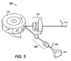
- Raster output scanner 102 includes a laser source 104 (the polarization multiplexing laser structure 20 of Figure 2) that outputs multiple laser beams 106 (two beams shown in Figure 5) from a substantially common spatial location. For purposes of clarity, only the chief rays are shown. Each beam is independently modulated with data appropriate to expose a photoreceptive element in accordance with a desired image.
- An input optical system 108 serves to direct laser beams 106 onto overlapping coaxial optical paths such that they illuminate a rotating polygon 110 having a plurality of facets 112.
- the rotating polygon 110 repeatedly and simultaneously deflects the laser beams in the direction indicated by the arrow 116.
- the deflected laser beams are input to a single set of imaging and correction optics 118, which focus the laser beams and correct for errors such as polygon angle error and wobble.
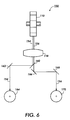
- the raster output scanner 102 is used in a first embodiment apparatus 150 as illustrated in Figure 6 (not all components of the scanner being shown in Figure 6).
- the raster output scanner 102 outputs two laser beams designated 154 and 156.
- those beams have substantially the same optical wavelength, but are linearly polarized in orthogonal directions in the plane perpendicular to their propagation direction. Again, only the chief rays are shown.
- a polarized beam separator 160 separates the laser beams 154 and 156 after they pass through correction optics 118.
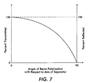
- the beam separator 160 is a polarization selective, multiple layer film, having the optical characteristics shown in Figure 7. Details of the beam separator 160 are subsequently described in more detail.
- a mirror 162 reflects the separated laser beam 154 onto a photoreceptor 164, while mirrors 166 and 168 reflect laser beam 156 onto a photoreceptor 170.
- the apparatus 150 may be used for two color printing where the image created on each photoreceptor corresponds to a different system color.
- the optical components 160, 162, 166, and 168 are oriented so that the optical path lengths from the laser source 104 (not shown) to the photoreceptors 164 and 170 are substantially equal.
- the dual laser beam apparatus of Figure 6 uses a polarization multiplexing laser structure 20 of Figures 2 and 3 that generates coaxially overlapping, cross-polarized laser beams with a common spatial origin for both laser beams.
- the polarized beam separator 160 has optical transmission/reflection characteristics as shown in Figure 7.
- the laser beam 156 is aligned to be linearly polarized at 0° with respect to the axis of the polarized beam separator 160, while coaxial laser beam 154 is linearly polarized at 90° with respect to the axis of the polarized beam separator. Therefore, laser beam 156 passes through the polarized beam separator 160, while laser beam 154 is reflected at nominally 45° with respect to the direction of propagation of laser beams.
- Polarized beam separators are well known to those in the applicable arts. Reference may be made to Vol. 10 of Applied Optics and Optical Engineering, edited by R.R. Shannon and J.C. Wyant, CHAPTER 10, PP 51-52.
- the problem of registration is reduced since the characteristics of the mirror surface area and the related optics which respectively sweep and form both beams are common to both beams. Furthermore, since both beams are nominally at the same wavelength, the beam forming optics do not have to be designed to simultaneously focus two wavelengths at the same distance.
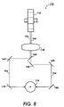
- FIG 8 shows a simplified schematic view of a second embodiment apparatus 175.
- Apparatus 175 is a single station/multiposition printer using the raster output scanner 102, including polygon 110 and optics 118, to simultaneously deflect two laser beams across spatially separated regions of one moving photoreceptor 176.
- each laser beam has nominally the same optical wavelength but is orthogonally polarized with respect to the other.
- a polarized beam separator 160 separates the laser beams after they pass through the correction optics 118.
- mirrors 162 and 178 serve to direct the deflected laser beam 154 onto photoreceptor 176, while mirrors 166, 168 and 180 serve to direct laser beam 156 onto a separate region of photoreceptor 176.
- a two color xerographic print engine may be produced. Although details of the structure and operation of such means are beyond the scope of the present disclosure, they are well known to those skilled in the art. Nevertheless, it is evident that utilization of the present invention in conjunction with a single photoreceptive drum or belt provides advantages similar to those described in conjunction with two separate xerographic stations.
- the semiconductor laser source 190 of Figure 9 consists of two polarization multiplexed lasers 192 and 194 emitting light at different wavelengths.
- the first laser 192 will emit light in both the TE- and TM-mode, as discussed previously in Figure 2, at a first wavelength.
- the second laser 194 will emit light in both the TE- and TM-mode, as discussed previously in Figure 2, at a second wavelength different from the first wavelength.
- Fabricating adjacent lasers which emit different wavelengths of light in a monolithic or non-monolithic structure is known in the art.
- the four beams with dissimilar wavelengths and dissimilar polarization states are emitted by a two-laser source.
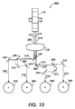
- FIG 10 shows a simplified, schematic view of a third embodiment apparatus 200 in which four laser beams, designated laser beams 214, 216, 218, and 220, are simultaneously scanned across four moving photoreceptors 250, 260, 270, 280. Again, only the chief rays are shown.
- the apparatus 200 a multiple station printer, uses the raster output scanner 102, including polygon 110 and optics 118 and laser device 104, such as the semiconductor laser source 190 of Figure 10, to produce the four laser beams (not all components of the raster output scanner 102 are shown in Figure 11).
- the laser beams 214, 216, 218, 220 are input to a polarized beam separator 160 (whose characteristics are discussed above and whose use is discussed below).
- Two of the beams i.e. laser beams 216 and 218, nominally have the same wavelength, for example 650nm, but are linearly polarized at 90° with respect to the axis of the polarized beam separator 60.
- the other two laser beams i.e. laser beams 214 and 220, nominally have the same wavelength, for example 600nm, which differs from the wavelength of laser beams 216 and 218.
- Laser beams 214 and 216 are aligned to be linearly polarized at 0° with respect to the axis of a polarized beam separator 60.
- polarized beam separator 160 separates the overlapping laser beams 214 and 216 from laser beams 218 and 220.
- Laser beams 218 and 220 are input into a dichroic beam separator 230, while laser beams 214 and 216 first reflect off of a mirror 234 and are then input into a dichroic beam separator 240.
- the dichroic beam separators 230 and 240 are wavelength selective multiple layer films having optical characteristics similar to those shown in Figure 11 (discussed below). Thus, the dichroic beam separator 230 separates the overlapping beams 218 and 220, while the dichroic beam separator 240 separates the overlapping beams 214 and 216.
- a mirror 242 then reflects the separated laser beam 214 onto a photoreceptor 250, while mirrors 252 and 254 reflect the separated laser beam 216 onto a photoreceptor 260.
- a mirror 262 reflects the separated laser beam 220 onto a photoreceptor 270, while mirrors 272 and 274 reflect the separated laser beam 218 onto a photoreceptor 280. Since each laser beam is independently modulated with image information, a distinct latent image is simultaneously printed on each photoreceptor. Thus apparatus 200 may be used for full color reproduction, wherein the image on each photoreceptor corresponds to a different system color.
- the apparatus of Figure 10 uses a laser device 190 shown in Figure 9 that generates four coaxially overlapping, cross-polarized laser beams of two dissimilar wavelengths using either a monolithic diode laser array or two non-monolithic diode lasers closely spaced in a single integrated package.
- the use of two wavelengths considerably simplifies the construction of the laser device and the requirements placed on the photoreceptive elements.
- the use of two polarization states from a single multiplexed laser also simplifies the construction of the laser device and the requirements placed on the photoreceptive elements.
- the dichroic beam separators 230 and 240 have the transmission/reflection characteristics shown in Figure 11.
- the curve 306 represents the characteristics of the optical filter when light strikes at a 45° angle of incidence
- curve 308 represents the filter's characteristics when light strikes at a 60° angle of incidence.
- changes in the transmission/reflection characteristics of the dichroic beam separators as the laser beams are scanned through angles as large as 15° have inconsequential effects on the apparatus performance.
- Such dichroic mirrors are well known in the art. Reference may be made to Volume 1 of "Applied Optics and Optical Engineering", (1965) edited by R. Kingslake, for example, at chapter 5, number IV and chapter 8, numbers VIII and IX.
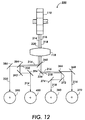
- FIG 12 shows a simplified schematic view of a fourth embodiment apparatus 300 in which four laser beams are simultaneously scanned across four moving photoreceptors. Again, only the chief rays are shown.
- Apparatus 300 is a multiple station printer that uses the raster output scanner 102 (not all of whose components are shown in Figure 12), including polygon 110 and optics 118, to simultaneously deflect four laser beams, designated laser beams 214, 216, 218, and 220, which are obtained from laser device 190 shown in Figure 9.
- the four laser beams in Figure 12 are identical to the four laser beams described in conjunction with Figure 10 and may thus be derived from the same laser source 104.
- a dichroic beam separator 360 having optical characteristics similar to those shown in Figure 11, first separates laser beams 216 and 218 from laser beams 214 and 220.
- a polarized beam separator 366 having transmission characteristics as shown in Figure 7, then separates the overlapping beams 216 and 218.
- Mirror 368 directs the separated laser beam 216 onto a photoreceptor 370, while mirrors 372 and 374 reflect separated laser beam 218 onto a photoreceptor 380.
- a polarized beam separator 384 having transmission characteristics substantially similar to those of polarized beam separator 366, separates overlapping beams 214 and 220.
- a mirror 386 reflects the separated laser beam 220 onto a photoreceptor 390, while mirrors 392 and 394 reflect the separated laser beam 214 onto a photoreceptor 400. Since each laser beam is independently modulated with image information, distinct latent images are simultaneously impressed on each photoreceptor. Thus, the apparatus 300 is suitable for full color reproduction, wherein each laser beam produces a distinct latent image on its associated photoreceptor which corresponds to its associated system color, substantially as described in conjunction with the embodiment of Figure 10.
- Such other sections include, for example, a photoreceptive belt or drum, means for moving the photoreceptor, means for charging the photoreceptor, means for forming a latent image on the photoreceptor, means for transferring the latent image to paper, means for erasing the latent image from the photoreceptor, means for cleaning the photoreceptor, paper transport means, and means for fusing the image onto the paper.
- Polarization multiplexing involves a single laser switching the polarization of the emitted laser beam between two orthogonal polarization states during each pixel time. This system uses fast laser switching with the polarization multiplexed laser and passive optical separation components.
- the number of different lasers required for the multiple beam raster output scanning system is halved.
- the complexity of the semiconductor laser source is significantly reduced, especially in the arrangement of the electrical contacts required to separately address each laser in the array.
- the field of view of the ROS optics is significantly reduced since the physical extent of the laser array is decreased.
- the single multiplexed polarization laser source which is rapidly and independently addressable, emits two beams of different polarizations which are coincident. This laser source simplifies the optical system of the raster output scanning system and the modulation scheme.
- a single semiconductor laser growth can be used to make a dual polarization structure.
- multiple growths were required for a dual polarization structure with separate growths for each polarization. Multiple growths reduces yield and requires more difficult processing.
- wavelengths for each polarization are very close (within 5nm) since the two beams come from the same laser active region. Therefore, chromatic dispersion problems in the optics are avoided. In the multiple growth approach, wavelengths must be well-matched for two separate different growths, limiting yield.
- the peak power required from each laser is increased since each pixel time is effectively halved.
- the average power required from each laser is doubled since each laser is printing two channels.
- the requisite power increases are well within current semiconductor structure technology.
- the clock rate for the system is doubled and consequently the electronics must be twice as fast.
- the needed electronics are well within current semiconductor structure technology.
- Pixel placement at multiplexed positions may need tangential compensation to correct for the non-simultaneous emission of the pixels from the same laser.
- a parallel plate may be used to move the appropriate pixel tangentially or unequal path lengths to the multiplexed positions may be used to achieve simultaneous exposures on the photoreceptor(s).
Landscapes
- Engineering & Computer Science (AREA)
- Multimedia (AREA)
- Signal Processing (AREA)
- Mechanical Optical Scanning Systems (AREA)
- Facsimile Scanning Arrangements (AREA)
- Dot-Matrix Printers And Others (AREA)
- Laser Beam Printer (AREA)
Applications Claiming Priority (2)
| Application Number | Priority Date | Filing Date | Title |
|---|---|---|---|
| US58168995A | 1995-12-29 | 1995-12-29 | |
| US581689 | 1995-12-29 |
Publications (2)
| Publication Number | Publication Date |
|---|---|
| EP0782328A2 true EP0782328A2 (de) | 1997-07-02 |
| EP0782328A3 EP0782328A3 (de) | 1998-02-18 |
Family
ID=24326173
Family Applications (1)
| Application Number | Title | Priority Date | Filing Date |
|---|---|---|---|
| EP96309343A Withdrawn EP0782328A3 (de) | 1995-12-29 | 1996-12-20 | Rasterausgabeabtastsystem mit mehreren Strahlen mit Polarisationsmultiplexierung |
Country Status (2)
| Country | Link |
|---|---|
| EP (1) | EP0782328A3 (de) |
| JP (1) | JPH09193469A (de) |
Cited By (2)
| Publication number | Priority date | Publication date | Assignee | Title |
|---|---|---|---|---|
| US9065587B2 (en) | 2010-10-08 | 2015-06-23 | Hewlett-Packard Development Company, L.P. | Optical multiplexing using laser arrays |
| US9160481B2 (en) | 2010-10-08 | 2015-10-13 | Hewlett-Packard Development Company, L.P. | Optical polarization multiplexing using laser arrays |
Families Citing this family (4)
| Publication number | Priority date | Publication date | Assignee | Title |
|---|---|---|---|---|
| JP5359209B2 (ja) * | 2008-01-25 | 2013-12-04 | 株式会社リコー | 光走査装置、および画像形成装置 |
| JP2010151878A (ja) * | 2008-12-24 | 2010-07-08 | Dainippon Screen Mfg Co Ltd | 光ビーム分岐装置および露光装置 |
| JP5915049B2 (ja) * | 2011-09-16 | 2016-05-11 | 株式会社リコー | 画像形成装置 |
| JP5846427B2 (ja) * | 2011-12-14 | 2016-01-20 | 株式会社リコー | 光走査装置及び画像形成装置 |
Citations (2)
| Publication number | Priority date | Publication date | Assignee | Title |
|---|---|---|---|---|
| US5243339A (en) | 1988-06-07 | 1993-09-07 | The Boeing Company | Flight crew response monitor |
| US5343224A (en) | 1992-09-22 | 1994-08-30 | Xerox Corporation | Diode laser multiple output scanning system |
Family Cites Families (2)
| Publication number | Priority date | Publication date | Assignee | Title |
|---|---|---|---|---|
| JP2995925B2 (ja) * | 1991-06-14 | 1999-12-27 | ミノルタ株式会社 | レーザビーム合成方法 |
| US5412678A (en) * | 1992-09-22 | 1995-05-02 | Xerox Corporation | Multi-beam, orthogonally-polarized emitting monolithic quantum well lasers |
-
1996
- 1996-12-20 EP EP96309343A patent/EP0782328A3/de not_active Withdrawn
- 1996-12-25 JP JP8346315A patent/JPH09193469A/ja not_active Withdrawn
Patent Citations (2)
| Publication number | Priority date | Publication date | Assignee | Title |
|---|---|---|---|---|
| US5243339A (en) | 1988-06-07 | 1993-09-07 | The Boeing Company | Flight crew response monitor |
| US5343224A (en) | 1992-09-22 | 1994-08-30 | Xerox Corporation | Diode laser multiple output scanning system |
Non-Patent Citations (2)
| Title |
|---|
| R. KINGSLAKE: "Applied optics and optical engineering", vol. 1, 1965 |
| R.R. SHANNON, J.C. WYANT: "Applied optics and optical engineering", vol. 10, pages: 51 - 52 |
Cited By (2)
| Publication number | Priority date | Publication date | Assignee | Title |
|---|---|---|---|---|
| US9065587B2 (en) | 2010-10-08 | 2015-06-23 | Hewlett-Packard Development Company, L.P. | Optical multiplexing using laser arrays |
| US9160481B2 (en) | 2010-10-08 | 2015-10-13 | Hewlett-Packard Development Company, L.P. | Optical polarization multiplexing using laser arrays |
Also Published As
| Publication number | Publication date |
|---|---|
| EP0782328A3 (de) | 1998-02-18 |
| JPH09193469A (ja) | 1997-07-29 |
Similar Documents
| Publication | Publication Date | Title |
|---|---|---|
| US5325381A (en) | Multiple beam diode laser output scanning system | |
| US6002705A (en) | Wavelength and polarization multiplexed vertical cavity surface emitting lasers | |
| JP3645598B2 (ja) | 多重ビーム型ダイオードレーザアレイ及びそれを用いたレーザプリンタ | |
| US5243359A (en) | Raster output scanner for a multistation xerographic printing system | |
| US5784399A (en) | Polarization mode selection by distributed Bragg reflector in a quantum well laser | |
| CN102664348B (zh) | 表面发射激光器及阵列、光学扫描装置、成像设备、光学传输模块和系统 | |
| US7889224B2 (en) | Optical path switching device, optical scanning device, and image forming apparatus | |
| JP3212153B2 (ja) | 可変波長光源を用いた光学出力装置でのスポット位置制御用の装置 | |
| US5179462A (en) | Laser beam composite apparatus | |
| US5956070A (en) | Color xerographic printer with multiple linear arrays of surface emitting lasers with dissimilar polarization states and dissimilar wavelengths | |
| EP0844707B1 (de) | Mehrstrahllichtquelle und optisches Mehrstrahlabtastsystem unter Verwendung dieser Quelle | |
| Mukoyama et al. | VCSEL array-based light exposure system for laser printing | |
| US5157533A (en) | Multi-beam optical system | |
| EP0782328A2 (de) | Rasterausgabeabtastsystem mit mehreren Strahlen mit Polarisationsmultiplexierung | |
| JP3212152B2 (ja) | 可変波長光源を用いた光学出力装置でのスポット位置制御方法 | |
| US5341158A (en) | Raster output scanner for a xerographic printing system having laser diodes arranged in a line parallel to the fast scan direction | |
| US5371526A (en) | Raster output scanner for a single pass printing system which separates plural laser beams by wavelength and polarization | |
| US5343224A (en) | Diode laser multiple output scanning system | |
| JPH0394481A (ja) | アレイ状半導体発光装置 | |
| US5264869A (en) | Electro-optical control apparatus and system for spot position control in an optical output device | |
| EP0710009B1 (de) | Verfahren und Vorrichtung, um den Unterschied der Bildhöhen von Bildern, die durch mehrere Lichtstrahlen mit verschiedenen Höhen erzeugt werden, zu reduzieren | |
| US5574491A (en) | Apparatus spot position control in an output device employing a linear array of light sources | |
| US5995267A (en) | Time division multiplexing multiple beam raster output scanning system | |
| JPH10282440A (ja) | 光走査装置及び電子写真記録装置 | |
| US6055256A (en) | Laser beam printer and semiconductor laser device suitable for a light source thereof |
Legal Events
| Date | Code | Title | Description |
|---|---|---|---|
| PUAI | Public reference made under article 153(3) epc to a published international application that has entered the european phase |
Free format text: ORIGINAL CODE: 0009012 |
|
| AK | Designated contracting states |
Kind code of ref document: A2 Designated state(s): DE FR GB |
|
| PUAL | Search report despatched |
Free format text: ORIGINAL CODE: 0009013 |
|
| AK | Designated contracting states |
Kind code of ref document: A3 Designated state(s): DE FR GB |
|
| 17P | Request for examination filed |
Effective date: 19980818 |
|
| STAA | Information on the status of an ep patent application or granted ep patent |
Free format text: STATUS: THE APPLICATION HAS BEEN WITHDRAWN |
|
| 18W | Application withdrawn |
Withdrawal date: 19990310 |