EP0782128B1 - Verfahren zur Analyse eines Audiofrequenzsignals durch lineare Prädiktion, und Anwendung auf ein Verfahren zur Kodierung und Dekodierung eines Audiofrequenzsignals - Google Patents
Verfahren zur Analyse eines Audiofrequenzsignals durch lineare Prädiktion, und Anwendung auf ein Verfahren zur Kodierung und Dekodierung eines Audiofrequenzsignals Download PDFInfo
- Publication number
- EP0782128B1 EP0782128B1 EP96402715A EP96402715A EP0782128B1 EP 0782128 B1 EP0782128 B1 EP 0782128B1 EP 96402715 A EP96402715 A EP 96402715A EP 96402715 A EP96402715 A EP 96402715A EP 0782128 B1 EP0782128 B1 EP 0782128B1
- Authority
- EP
- European Patent Office
- Prior art keywords
- signal
- stage
- transfer function
- coefficients
- parameters
- Prior art date
- Legal status (The legal status is an assumption and is not a legal conclusion. Google has not performed a legal analysis and makes no representation as to the accuracy of the status listed.)
- Expired - Lifetime
Links
- 238000000034 method Methods 0.000 title claims description 74
- 238000004458 analytical method Methods 0.000 claims description 88
- 230000005284 excitation Effects 0.000 claims description 87
- 230000015572 biosynthetic process Effects 0.000 claims description 86
- 238000003786 synthesis reaction Methods 0.000 claims description 86
- 238000012546 transfer Methods 0.000 claims description 79
- 230000008569 process Effects 0.000 claims description 35
- 230000003595 spectral effect Effects 0.000 claims description 29
- 238000013139 quantization Methods 0.000 claims description 24
- 238000001914 filtration Methods 0.000 claims description 20
- 238000001228 spectrum Methods 0.000 claims description 20
- 238000004519 manufacturing process Methods 0.000 claims description 9
- 230000001419 dependent effect Effects 0.000 claims description 3
- 230000006870 function Effects 0.000 description 53
- 241000897276 Termes Species 0.000 description 27
- 238000011002 quantification Methods 0.000 description 14
- 230000005236 sound signal Effects 0.000 description 11
- 235000021183 entrée Nutrition 0.000 description 9
- 230000004044 response Effects 0.000 description 9
- 241000135309 Processus Species 0.000 description 8
- 230000006978 adaptation Effects 0.000 description 8
- 238000010586 diagram Methods 0.000 description 7
- 230000007774 longterm Effects 0.000 description 7
- 238000012545 processing Methods 0.000 description 6
- 230000001934 delay Effects 0.000 description 4
- 230000003044 adaptive effect Effects 0.000 description 3
- 230000006872 improvement Effects 0.000 description 3
- 230000000873 masking effect Effects 0.000 description 3
- 238000005070 sampling Methods 0.000 description 3
- 150000001875 compounds Chemical class 0.000 description 2
- 238000011156 evaluation Methods 0.000 description 2
- 230000002441 reversible effect Effects 0.000 description 2
- 230000005540 biological transmission Effects 0.000 description 1
- 238000006243 chemical reaction Methods 0.000 description 1
- 239000002131 composite material Substances 0.000 description 1
- 230000006835 compression Effects 0.000 description 1
- 238000007906 compression Methods 0.000 description 1
- 238000007796 conventional method Methods 0.000 description 1
- 239000011159 matrix material Substances 0.000 description 1
- 230000008447 perception Effects 0.000 description 1
- 238000007493 shaping process Methods 0.000 description 1
Images


Classifications
-
- G—PHYSICS
- G10—MUSICAL INSTRUMENTS; ACOUSTICS
- G10L—SPEECH ANALYSIS TECHNIQUES OR SPEECH SYNTHESIS; SPEECH RECOGNITION; SPEECH OR VOICE PROCESSING TECHNIQUES; SPEECH OR AUDIO CODING OR DECODING
- G10L19/00—Speech or audio signals analysis-synthesis techniques for redundancy reduction, e.g. in vocoders; Coding or decoding of speech or audio signals, using source filter models or psychoacoustic analysis
- G10L19/04—Speech or audio signals analysis-synthesis techniques for redundancy reduction, e.g. in vocoders; Coding or decoding of speech or audio signals, using source filter models or psychoacoustic analysis using predictive techniques
- G10L19/06—Determination or coding of the spectral characteristics, e.g. of the short-term prediction coefficients
Definitions
- the present invention relates to a method of analysis by linear prediction of an audio signal.
- This process finds a particular, but not exclusive, application in prediction audio coders, especially in coders with analysis by synthesis, the most common type of which is the coder CELP ("Code-Excited Linear Prediction").
- Predictive coding techniques with analysis by synthesis are currently widely used for coding the speech in the telephone band (300-3400 Hz) at rates that can down to 8 kbit / s, while maintaining quality telephone.
- the transform coding techniques are used for voice signal broadcasting and storage applications and musical.
- these techniques involve delays in relatively large coding (larger than 100 ms), which produces in particular difficulties in participating in group communications where interactivity is very important.
- Predictive techniques delay lower, essentially depending on the length of the frames linear prediction analysis (typically 10 to 20 ms), and therefore find applications even for coding voice and / or music signals having bandwidth greater than the telephone band.
- the predictive coders used for bit rate compression perform modeling of the spectral envelope of the signal. This modeling results from an analysis by linear prediction of order M (M-10 typically in narrow band), consisting in determining M coefficients a i of linear prediction of the input signal. These coefficients characterize a synthesis filter used at the decoder, whose transfer function is of the form 1 / A (z) with
- Linear prediction analysis has a domain of broader application than that of coding the speech.
- the order M of the prediction is one of the variables that predictive analysis linear aims to obtain, this variable being influenced by the number of peaks present in the spectrum of the signal analyzed (see US-A-5,142,581).
- the filter calculated by the linear prediction analysis can have various structures, leading to different choices of parameters for the representation of the coefficients (the coefficients a i themselves, the parameters LAR, LSF, LSP, the reflection coefficients or PARCOR. ..).
- DSP digital signal processors
- it was common to use recursive structures for the calculated filter for example structures using PARCOR coefficients of the type described in the article by F. ITAKURA and S. SAITO "Digital Filtering Techniques for Speech Analysis and Synthesis", Proc. of the 7th International Congress on Acoustics, Budapest 1971, pages 261-264 (see FR-A-2 284 946 or US-A-3 975 587).
- the coefficients a i are also used to construct a perceptual weighting filter used by the coder to determine the excitation signal to be applied to the short-term synthesis filter to obtain a synthetic signal representative of the signal of speech.
- This perceptual weighting accentuates the portions of the spectrum where the coding errors are the most perceptible, that is to say the interformant areas.
- the linear prediction coefficients a i are also used to define a post-filter used to attenuate the frequency zones between the formants and the harmonics of the speech signal, without modifying the slope of the spectrum of the signal.
- G P is a gain factor compensating for the attenuation of the filters
- ⁇ 1 and ⁇ 2 are coefficients such that 0 ⁇ 1 ⁇ 2 ⁇ 1, ⁇ is a positive constant
- r 1 denotes the first dependent reflection coefficient coefficients a i .
- Modeling the spectral envelope of the signal by the coefficients a i therefore constitutes an essential element of the coding and decoding process, in the sense that it must represent the spectral content of the signal to be reconstructed at the decoder and that it also controls masking quantization noise as well as post-filtering at the decoder.
- linear prediction analysis usually practiced fails to faithfully model the envelope of the spectrum. Often the speech signals are noticeably more energetic at low frequencies than at frequencies so that the linear prediction analysis certainly leads to precise bass modeling frequencies but at the expense of spectrum modeling at higher frequencies. This drawback becomes particularly troublesome in the case of wideband coding.
- US Patent 5,142,581 describes a filter for multistage linear prediction, in which the order prediction used in each stage is a variable parameter.
- An object of the present invention is to improve the modeling of the spectrum of an audiofrequency signal in a system using a prediction analysis method linear. Another goal is to make the performance of a such more homogeneous system for different input signals (speech, music, sinusoids, DTMF signals %), different bandwidths (telephone band, band enlarged, hifi band %), different recording conditions (directive microphone, acoustic antenna %) and filtering.
- the invention thus proposes a method of analysis by linear prediction of order M of an audiofrequency signal, to determine spectral parameters dependent on a short-term spectrum of the audiofrequency signal, divided into q successive prediction stages, q being an integer greater than 1.
- parameters are determined representing a predefined number Mp of coefficients a 1 P , ..., a Mp p of linear prediction of an input signal from said stage , the audio signal analyzed constituting the input signal of the first stage, and the input signal of a stage p + 1 being constituted by the input signal of stage p filtered by a transfer function filter the prediction order M being such that
- the number Mp of linear prediction coefficients can notably increase from one floor to the next. So the first floor will be able to fairly accurately reflect the general slope of the spectrum or signal, while the stages following will refine the representation of the signal formants. This avoids, in the case of high dynamic signals, too much focus on the most energetic areas at risk poor modeling of other frequency zones which may be perceptually important.
- the transfer function A (z) thus obtained can also be used to define according to formula (2) the transfer function of the perceptual weighting filter when the coder is a coder for analysis by synthesis with closed loop determination of the signal of excitation.
- Another interesting possibility is to adopt coefficients of spectral expansion ⁇ 1 and ⁇ 2 which can vary from one stage to the next, that is to say to give the perceptual weighting filter a function of transfer of the form.
- ⁇ 1 p , ⁇ 2 p denote pairs of spectral expansion coefficients such that 0 ⁇ 2 p ⁇ 1 p ⁇ 1 for 1 ⁇ p ⁇ q.
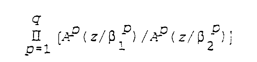
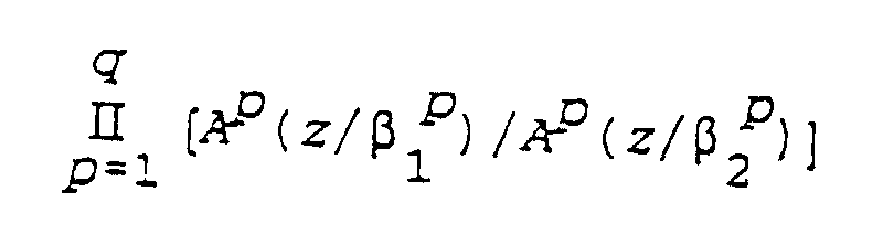
- This transfer function A (z) can also be used to define a post-filter whose transfer function comprises, as in formula (3) above, a term of the form A (z / ⁇ 1 ) / A (z / ⁇ 2 ), where ⁇ 1 and ⁇ 2 denote coefficients such as 0 ⁇ 1 ⁇ 2 ⁇ 1.
- stepwise linear prediction analysis method multiple proposed according to the invention has many other applications in audio signal processing, for example example in transform predictive coders, in speech recognition systems in systems speech enhancement ...
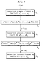
- the audiofrequency signal to be analyzed in the method illustrated in FIG. 1 is denoted s 0 (n). It is assumed to be available in the form of digital samples, the integer n denoting the successive sampling instants.
- the linear prediction analysis method comprises q successive stages 5 1 , ..., 5 p , ..., 5 q . At each prediction stage 5 p (1 p p q q), a linear order Mp prediction of an input signal s p-1 (n) is carried out.
- the input signal of the first stage 5 1 is constituted by the audio frequency signal to be analyzed s 0 (n), while the input signal of a stage 5 p + 1 (1 ⁇ p ⁇ q) is constituted by the signal s p (n), obtained in a step denoted 6 p by applying to the input signal s p-1 (n) of the p-th stage 5 p a filtering by means of a transfer function filter where the coefficients a i p (1 ⁇ i ⁇ Mp) are the linear prediction coefficients obtained on stage 5 p .
- the quantity E (Mp) is the energy of the residual prediction error of stage p.
- the quantification can relate to the normalized frequencies ⁇ i p or to their cosines.
- the analysis can be performed at each 5 p prediction stage according to the classic Levinson-Durbin algorithm mentioned above.
- Other algorithms providing the same results, developed more recently, can be used advantageously, in particular the exploded Levinson algorithm (see “A new Efficient Algorithm to Compute the LSP Parameters for Speech Coding", by S. Saoudi, JM Boucher and A. Le Guyader, Signal Processing, Vol.28, 1992, pages 201-212), or the use of Chebyshev polynomials (see “The Computation of Line Spectrum Frequencies Using Chebyshev Polynomials, by P. Kabal and RP Ramachandran, IEEE Trans. On Acoustics, Speech, and Signal Processing, Vol. ASSP-34, n ° 6, pages 1419-1426, December 1986).
- the orders Mp of the linear predictions carried out preferably increase from one stage to the following: M1 ⁇ M2 ⁇ ... ⁇ Mq.
- M1 2 for example
- M1 2 for example
- the signal sampling frequency Fe was 16 kHz.
- the signal spectrum (modulus of its Fourier transform) is represented by curve I. This spectrum is representative of audio frequency signals which have, on average, more energy at low frequencies than at high frequencies. The spectral dynamics are sometimes higher than that of Figure 2 (60 dB).
- Curves (II) and (III) correspond to the modeled spectral envelopes
- the invention is described below in its application to a CELP type speech coder.
- FIG. 3 The speech synthesis process implemented in a CELP coder and decoder is illustrated in FIG. 3.
- An excitation generator 10 delivers an excitation code c k belonging to a predetermined repertoire in response to an index k.
- An amplifier 12 multiplies this excitation code by an excitation gain ⁇ , and the resulting signal is subjected to a long-term synthesis filter 14.
- the output signal u of the filter 14 is in turn subjected to a short-term synthesis filter 16, the output of which constitutes what is considered here as the synthetic speech signal.
- This synthetic signal is applied to a post-filter 17 intended to improve the subjective quality of the reconstructed speech.
- Post-filtering techniques are well known in the field of speech coding (see JH Chen and A.
- the coefficients of the post-filter 17 are obtained from the LPC parameters characterizing the short-term synthesis filter 16. It will be understood that, as in certain current CELP decoders, the post-filter 17 could also include a long-term post-filtering component.
- the aforementioned signals are digital signals represented for example by words of 16 bits at a sampling rate Fe equal for example to 16 kHz for an encoder in wide band (50-7000 Hz).
- the synthesis filters 14, 16 are generally purely recursive filters.
- the delay T and the gain G constitute long-term prediction parameters (LTP) which are determined adaptively by the coder.
- the LPC parameters defining the short-term synthesis filter 16 are determined at the coder by a method of analysis by linear prediction of the speech signal.
- the transfer function of the filter 16 is generally of the form 1 / A (z) with A (z) of the form (1).
- the present invention proposes to adopt a similar form of the transfer function, in which A (z) is broken down according to (7) as indicated above.
- excitation signal designates here the signal u (n) applied to the short-term synthesis filter 14.
- This excitation signal comprises an LTP Gu (nT) component and a residual component, or innovation sequence, ⁇ c k (n).
- the parameters characterizing the residual component and, optionally, the LTP component are evaluated in a closed loop, using a perceptual weighting filter.
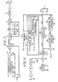
- FIG 4 shows the diagram of a CELP coder.
- the speech signal s (n) is a digital signal, for example supplied by an analog-to-digital converter 20 processing the amplified and filtered output signal from a microphone 22.
- LPC, LTP and EXC parameters index k and gain excitation ⁇
- LPC, LTP and EXC parameters index k and gain excitation ⁇
- These parameters are then quantified in a known manner for transmission efficient digital and then subjected to a multiplexer 30 which forms the encoder output signal.
- These parameters are also supplied to a module 32 for calculating initial states some encoder filters.
- This module 32 essentially comprises a decoding chain such as that shown in FIG. 3. Like the decoder, the module 32 operates on the basis of quantified LPC, LTP and EXC parameters. If one interpolation of LPC parameters is performed at the decoder, as is common, the same interpolation is performed by the module 32.
- the module 32 makes it possible to know at the level of the coder the previous states of the synthesis filters 14, 16 of the decoder, determined according to the synthesis parameters and excitation prior to the sub-frame considered.
- the next step in coding is determining LTP long term prediction parameters. These are for example determined once per L subframe samples.
- the signal outlet of the subtractor 34 is subjected to a filter 38 of perceptual weighting whose role is to accentuate portions of the spectrum where errors are most noticeable, that is to say the inter-forming zones.
- the respective coefficients b i and c i (1 i i M M) of the functions AN (z) and AP (z) are calculated for each frame by a module 39 for evaluating the perceptual weighting which supplies them to the filter 38.
- AN (z) A (z / ⁇ 1 )
- AP (z) A (z / ⁇ 2 ) with 0 ⁇ 2 ⁇ 1 ⁇ 1, which comes back to the usual form (2 ) with A (z) of the form (7).
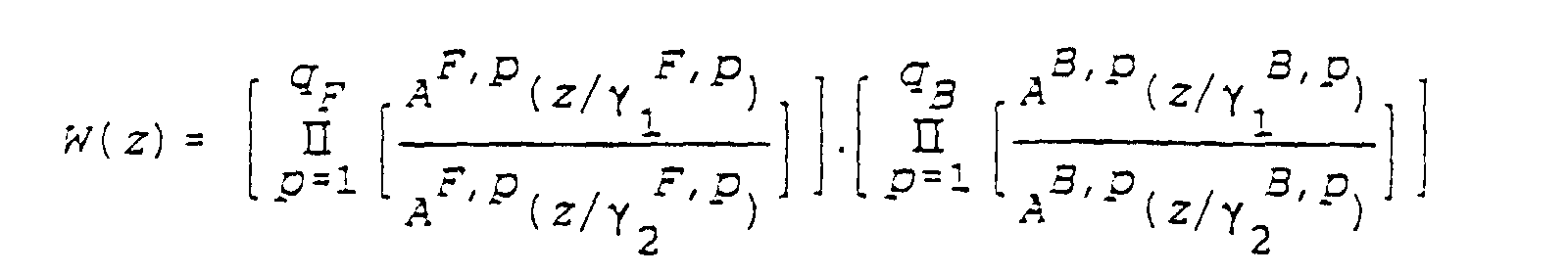
- the invention however allows, with a very low computational overload, to have greater flexibility as regards the shaping of the quantization noise, by adopting the form (6) for W (z), that is:
- the closed loop LTP analysis performed by the module 26 consists, in a conventional manner, in selecting for each subframe the delay T which maximizes the normalized correlation: where x '(n) denotes the output signal of the filter 38 during the sub-frame considered, and y T (n) denotes the convolution product u (nT) * h' (n).
- h '(0), h' (1) ..., h '(L-1) denotes the impulse response of the weighted synthesis filter, with transfer function W (z) / A (z).
- This impulse response h ′ is obtained by a module 40 for calculating impulse responses, as a function of the coefficients b i and c i provided by the module 39 and of the LPC parameters which have been determined for the sub-frame, if appropriate after quantification. and interpolation.
- the samples u (nT) are the previous states of the long-term synthesis filter 14, provided by the module 32.
- the missing samples u (nT) are obtained by interpolation on the basis of previous samples, or from the speech signal.
- the delays T, whole or fractional, are selected in a specific window.
- the signal Gy T (n) which has been calculated by the module 26 for the optimal delay T, is first subtracted from the signal x '(n) by the subtractor 42.
- the resulting signal x (n) is subjected to a reverse filter 44 which provides a signal D (n) given by: where h (0), h (1), ..., h (L-1) designates the impulse response of the filter composed of the synthesis filters and the perceptual weighting filter, calculated by the module 40.
- the compound filter has the transfer function W (z) / [A (z) .B (z)].
- the vector D constitutes a target vector for the module 28 for searching for the excitation.
- the CELP decoder includes a demultiplexer 8 receiving the bit stream from the coder.
- the quantized values of the excitation parameters EXC and LTP and LPC synthesis parameters are provided to the generator 10, amplifier 12 and filters 14, 16 to reconstruct the synthetic signal s and, which is subjected to post-filter 17 then converted to analog by the converter 18 before being amplified and then applied to a loudspeaker 19 to restore the original speech.
- the LPC parameters are for example constituted by quantization indexes of the reflection coefficients r i p (also called partial correlation coefficients or PARCOR) relating to the different linear prediction stages.
- a module 15 recovers the quantized values of the r i p from the quantization indexes, and converts them to provide the q sets of linear prediction coefficients. This conversion is for example carried out by the same recursive method as in the Levinson-Durbin algorithm.
- the sets of coefficients a i p are supplied to the short-term synthesis filter 16 constituted by a succession of q filters / stages of transfer functions 1 / A 1 (z), ..., 1 / A q (z) given by relation (4).
- the filter 16 could also be in a single stage of transfer function 1 / A (z) given by the relation (1) in which the coefficients a i have been calculated according to the relations (9) to (13).
- the reflection coefficient r 1 can be that associated with the coefficients a i of the composite synthesis filter, which it is then necessary to calculate.
- the invention makes it possible to adopt coefficients ⁇ 1 and ⁇ 2 different from one stage to the next (formula (8)), namely:
- the invention has been described above in its application to a predictive coder with forward adaptation, that is to say in which the audio signal subject to linear prediction analysis is the input signal of the coder.
- the invention also applies to predictive coders / decoders with backward adaptation, in which synthetic signal is subject to prediction analysis linear to the coder and the decoder (see J.H. Chen et al: "A Low-Delay CELP Coder for the CCITT 16 kbit / s Speech Coding Standard ", IEEE J.SAC, Vol.10, n ° 5, pages 830-848, June 1992).
- Figures 5 and 6 respectively show a decoder CELP and a "backward" adaptation CELP coder implements the present invention. Numerical references identical to those of FIGS. 3 and 4 were used to designate similar elements.
- the "backward" adaptation decoder receives only the quantization values of the parameters defining the excitation signal u (n) to apply to the synthesis filter in the short term 16.
- these parameters are the index k and the associated gain ⁇ as well as the parameters LTP.
- the synthetic signal s and (n) is processed by a module 124 analysis by linear multistage prediction identical to module 24 of FIG. 3.
- Module 124 provides the LPC parameters at filter 16 for one or more frames following of the excitation signal, and to the post-filter 17 of which the coefficients are obtained as described above.
- the corresponding encoder performs multi-stage linear prediction analysis on the synthetic signal generated locally and not on the signal audio s (n). It thus includes a local decoder 132 consisting essentially of the elements marked 10, 12, 14, 16 and 124 of the decoder in Figure 5. Besides the samples u from the adaptive dictionary and the initial states s and du filter 36, the local decoder 132 provides the LPC parameters obtained by synthetic signal analysis, which are used by module 39 for evaluating perceptual weighting and the module 40 for calculating the impulse responses h and h '. For the rest, the operation of the encoder is identical to that of the encoder described with reference to FIG. 4, except that the LPC 24 analysis module is no longer necessary. Only the EXC and LTP parameters are sent to the decoder.
- Figures 7 and 8 are block diagrams of a CELP decoder and a CELP coder with mixed adaptation.
- the linear prediction coefficients of the first stage (s) result from a forward analysis of the audio signal performed by the encoder, while the coefficients of linear prediction of the last stage (s) result from a "backward" analysis of the synthetic signal performed by the decoder (and by a local decoder provided in the coder).
- the coefficients of linear prediction of the last stage result from a "backward" analysis of the synthetic signal performed by the decoder (and by a local decoder provided in the coder).
- the mixed decoder illustrated in FIG. 7 receives the quantization values of the parameters EXC, LTP defining the excitation signal u (n) to be applied to the short-term synthesis filter 16, and the quantization values of the determined LPC / F parameters by the "forward" analysis performed by the coder.
- These LPC / F parameters represent q F sets of linear prediction coefficients a 1 F, p , ..., a MFp F, p for 1 ⁇ p ⁇ q F , and define a first component 1 / A F (z) of the transfer function 1 / A (z) of filter 16:
- the mixed decoder comprises an inverse filter 200 of transfer function A F (z) which filters the synthetic signal s and (n) produced by the short-term synthesis filter 16 to produce a filtered synthetic signal s and 0 (n).
- the LPC / B coefficients thus obtained are supplied to the synthesis filter 16 to define its second component for the next frame.
- the local decoder 232 provided in the mixed encoder consists essentially of the elements noted 10, 12, 14, 16, 200 and 224 / B of the decoder of Figure 7.
- the local decoder 232 provides the LPC / B parameters that are used, with LPC / F parameters provided by analysis module 224 / F, by module 39 Perception Weighting Assessment and Module 40 for calculating the impulse responses h and h '.
- the operation of the mixed encoder is identical to that of the encoder described with reference to the figure 4. Only EXC, LTP and LPC / F parameters are sent to the decoder.
Landscapes
- Engineering & Computer Science (AREA)
- Physics & Mathematics (AREA)
- Spectroscopy & Molecular Physics (AREA)
- Computational Linguistics (AREA)
- Signal Processing (AREA)
- Health & Medical Sciences (AREA)
- Audiology, Speech & Language Pathology (AREA)
- Human Computer Interaction (AREA)
- Acoustics & Sound (AREA)
- Multimedia (AREA)
- Compression, Expansion, Code Conversion, And Decoders (AREA)
Claims (22)
- Verfahren zur Analyse eines Tonfrequenzsignals (s0(n)) durch lineare Prädiktion der Ordnung M zur Bestimmung von Spektralparametern abhängig von einem Kurzzeitspektrum des Tonfrequenzsignals,
dadurch gekennzeichnet, daß das Verfahren unterteilt ist in q aufeinanderfolgende Prädiktionsstufen (5p), wobei q eine ganze Zahl größer als 1 ist, und daß man in jeder Prädiktionsstufe p (1 ≤ p ≤ q) Parameter bestimmt, welche eine für die jeweilige Stufe p im voraus festgelegte Zahl Mp von linearen Prädiktionskoeffizienten a1 p,..., aMp p eines Eingangssignals der Stufe repräsentieren, wobei das zu analysierende Tonfrequenzsignal das Eingangssignal (s0(n)) der ersten Stufe bildet und das Eingangssignal (sp(n)) einer Stufe p+1 von dem mittels eines Filters der Übertragungsfunktiongefilterten Eingangssignal (sp-1(n)) der Stufe p gebildet ist, wobei für die Prädiktionsordnung M gilt.
gilt.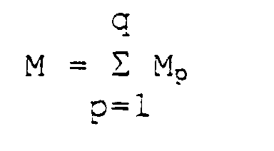
- Analyseverfahren nach Anspruch 1, dadurch gekennzeichnet, daß die Zahl Mp der linearen Prädiktionskoeffizienten von einer Stufe zur nächsten zunimmt.
- Verfahren zur Codierung eines Tonfrequenzsignals, umfassend die folgenden Schritte:dadurch gekennzeichnet, daß die Analyse durch lineare Prädiktion ein Vorgang in q aufeinanderfolgenden Stufen (5p) ist, wobei q eine ganze Zahl größer als 1 ist, wobei dieser Vorgang in jeder Prädiktionsstufe p (1 ≤ p ≤ q) die Bestimmung von Parametern umfaßt, welche eine für die jeweilige Stufe p im voraus festgelegte Zahl Mp vom linearen Prädiktionskoeffizienten a1 p,..., aMp p eines Eingangssignals der Stufe repräsentieren, wobei das zu codierende Tonfrequenzsignal (s(n)) das Eingangssignal (s0(n)) der ersten Stufe bildet und das Eingangssignal (sp(n)) einer Stufe p+1 von dem mittels eines Filters der ÜbertragungsfunktionAnalysieren des in aufeinanderfolgende Blöcke digitalisierten Tonfrequenzsignals (s(n)) durch lineare Prädiktion zur Bestimmung von Parametern (LPC), welche ein Kurzzeitsynthesefilter (16) definieren,Bestimmen von Anregungsparametern (k, β, LTP), welche ein Anregungssignal (u(n)) definieren, das zur Erzeugung eines das Tonfrequenzsignal repräsentierenden Synthesesignals (s and(n)) an das Kurzzeitsynthesefilter (16) anzulegen ist, undErzeugen von Quantisierungswerten der das Kurzzeitsynthesefilter definierenden Parameter und der Anregungsparameter,gefilterten Eingangssignal (sp-1(n)) der Stufe p gebildet ist, wobei das Kurzzeitsynthesefilter (16) eine Übertragungsfunktion der Form 1/A(z) mit
 besitzt.
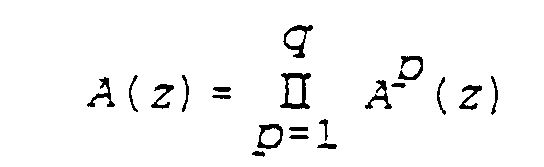
- Codierverfahren nach Anspruch 3, dadurch gekennzeichnet, daß die Zahl Mp der linearen Prädiktionskoeffizienten von einer Stufe zur nächsten zunimmt.
- Codierverfahren nach Anspruch 3 oder 4, dadurch gekennzeichnet, daß zumindest einige der Anregungsparameter bestimmt werden, indem die Energie eines Fehlersignals minimiert wird, welches aus der Filterung der Differenz zwischen dem Tonfrequenzsignal (s(n)) und dem Synthesesignal (s and(n)) mittels mindestens eines Wahrnehmungswichtungsfilters (38) resultiert, dessen Übertragungsfunktion die Form W(z) = A(z/γ1) / A(z/γ2) besitzt, wobei γ1 und γ2 spektrale Ausdehnungskoeffizienten mit 0 ≤ γ2 ≤ γ1 ≤ 1 bezeichnen.
- Codierverfahren nach Anspruch 3 oder 4, dadurch gekennzeichnet, daß zumindest einige der Anregungsparameter bestimmt werden, indem die Energie eines Fehlersignals minimiert wird, welches aus der Filterung der Differenz zwischen dem Tonfrequenzsignal (s(n)) und dem Synthesesignal (s and(n)) mittels mindestens eines Wahrnehmungswichtungsfilters (38) resultiert, dessen Übertragungsfunktion die Formbesitzt, wobei γ1 p, γ2 p Paare von spektralen Ausdehnungskoeffizienten mit 0 ≤ γ2 p ≤ γ1 p ≤ 1 für 1 ≤ p ≤ q bezeichnen.

- Verfahren zur Decodierung eines binären Stroms zur Erzeugung eines durch den binären Strom codierten Tonfrequenzsignals,
dadurch gekennzeichnet, daß man:Quantisierungswerte von Parametern (LPC), welche ein Kurzzeitsynthesefilter (16) definieren, und von Anregungsparametern (k, β, LTP) erhält, wobei die das Synthesefilter definierenden Parameter eine Zahl q, die größer als 1 ist, von Sätzen von linearen Prädiktionskoeffizienten (ai p) repräsentieren, wobei jeder Satz p eine im voraus festgelegte Zahl Mp von Koeffizienten umfaßt,auf Grundlage der Quantisierungswerte der Anregungsparameter ein Anregungssignal (u(n)) erzeugt undein synthetisiertes Tonfrequenzsignal (s and(n)) erzeugt, indem das Anregungssignal mittels eines Synthesefilters (16) mit einer Übertragungsfunktion der Form 1/A(z) mitgefiltert wird, wobei die Koeffizienten a1 p,..., aMp p dem p-ten Satz von linearen Prädiktionskoeffizienten entsprechen, wobei 1 ≤ p ≤ q.
- Decodierverfahren nach Anspruch 7, dadurch gekennzeichnet, daß das synthetisierte Tonfrequenzsignal (s and(n)) an ein Nachfilter (17) angelegt wird, dessen Übertragungsfunktion (HPF(z)) einen Term der Form A(z/β1/A(zβ2) umfaßt, wobei β1 und β2 Koeffizienten bezeichnen, für die 0 ≤ β1 ≤ β2 ≤ 1 gilt.
- Decodierverfahren nach Anspruch 7, dadurch gekennzeichnet, daß das synthetisierte Tonfrequenzsignal (s and(n)) an ein Nachfilter (17) angelegt wird, dessen Übertragungsfunktion (HPF(z)) einen Term der Formumfaßt, wobei β1 p, β2 p Paare von Koeffizienten bezeichnen, für die 0 ≤ β1 p ≤ β2 p ≤ 1 für 1 ≤ p ≤ q gilt, und wobei Ap(z) für den p-ten Satz von linearen Prädiktionskoeffizienten die Funktion
 repräsentiert.
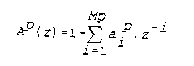
- Verfahren zur Codierung eines ersten, in aufeinanderfolgende Blöcke digitalisierten Tonfrequenzsignals, umfassend die folgenden Schritte:dadurch gekennzeichnet, daß die Analyse durch lineare Prädiktion ein Vorgang in q aufeinanderfolgenden Stufen (5p) ist, wobei q eine ganze Zahl größer als 1 ist, wobei dieser Vorgang in jeder Prädiktionsstufe p (1 ≤ p ≤ q) die Bestimmung von Parametern umfaßt, welche eine für die jeweilige Stufe p im voraus festgelegte Zahl Mp von linearen Prädiktionskoeffizienten a1 p,..., aMp p eines Eingangssignals der Stufe repräsentieren, wobei das zweite Tonfrequenzsignal (s and(n)) das Eingangssignal (s0(n)) der ersten Stufe bildet und das Eingangssignal (sp(n)) einer Stufe p+1 von dem mittels eines Filters der ÜbertragungsfunktionAnalysieren eines zweiten Tonfrequenzsignals (s and(n)) durch lineare Prädiktion zur Bestimmung von Parametern (LPC), welche ein Kurzzeitsynthesefilter (16) definieren,Bestimmen von Anregungsparametern (k, β, LTP), welche ein Anregungssignal (u(n)) definieren, das zur Erzeugung eines das erste Tonfrequenzsignal repräsentierenden Synthesesignals (s and(n)) an das Kurzzeitsynthesefilter (16) anzulegen ist, wobei dieses Synthesesignal für mindestens einen nachfolgenden Block das zweite Tonfrequenzsignal bildet, undErzeugen von Quantisierungswerten der Anregungsparameter,gefilterten Eingangssignal (sp-1(n)) der Stufe p gebildet ist, wobei das Kurzzeitsynthesefilter (16) eine Übertragungsfunktion der Form 1/A(z) mit
 besitzt.
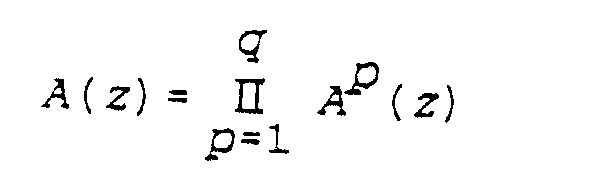
- Codierverfahren nach Anspruch 10, dadurch gekennzeichnet, daß die Zahl Mp von linearen Prädiktionskoeffizienten von einer Stufe zur nächsten zunimmt.
- Codierverfahren nach Anspruch 10 oder 11, dadurch gekennzeichnet, daß zumindest einige der Anregungsparameter bestimmt werden, indem die Energie eines Fehlersignals minimiert wird, welches aus der Filterung der Differenz zwischen dem ersten Tonfrequenzsignal (s(n)) und dem Synthesesignal (s and(n)) mittels mindestens eines Wahrnehmungswichtungsfilters (38) resultiert, dessen Übertragungsfunktion die Form W(z) = A(z/γ1)/A(z/γ2) besitzt, wobei γ1 und γ2 spektrale Ausdehnungskoeffizienten bezeichnen, für die 0 ≤ γ2 ≤ γ1 ≤ 1 gilt.
- Codierverfahren nach Anspruch 10 oder 11, dadurch gekennzeichnet, daß zumindest einige der Anregungsparameter bestimmt werden, indem die Energie eines Fehlersignals minimiert wird, welches aus der Filterung der Differenz zwischen dem ersten Tonfrequenzsignal (s(n)) und dem Synthesesignal (s and(n)) mittels mindestens eines Wahrnehmungswichtungsfilters (38) resultiert, dessen Übertragungsfunktion die Formbesitzt, wobei γ1 p, γ2 p Paare von spektralen Ausdehnungskoeffizienten bezeichnen, für die 0 ≤ γ2 p ≤ γ1 p ≤ 1 für 1 ≤ p ≤ q gilt.

- Verfahren zur Decodierung eines binären Stroms zur Erzeugung eines durch den binären Strom codierten Tonfrequenzsignals in aufeinanderfolgenden Blöcken,
dadurch gekennzeichnet, daß man:und daß die Analyse durch lineare Prädiktion ein Vorgang in q aufeinanderfolgenden Stufen (5p) ist, wobei q eine ganze Zahl größer als 1 ist, wobei dieser Vorgang in jeder Prädiktionsstufe p (1 ≤ p ≤ q) die Bestimmung von Parametern umfaßt, welche eine für die jeweilige Stufe p im voraus festgelegte Zahl Mp von linearen Prädiktionskoeffizienten a1 p,..., aMp p eines Eingangssignals der Stufe repräsentierten, wobei das synthetisierte Signal (s and(n)) das Eingangssignal (s0(n)) der ersten Stufe bildet und das Eingangssignal (sp(n)) einer Stufe p+1 von dem mittels eines Filters der ÜbertragungsfunktionQuantisierungswerte von Anregungsparametern (k, β, LTP) erhält,auf Grundlage der Quantisierungswerte der Anregungsparameter ein Anregungssignal (u(n)) erzeugt,durch Filterung des Anregungssignals mittels eines Kurzzeitsynthesefilters (16) ein synthetisiertes Tonfrequenzsignal (s and(n)) erzeugt,eine Analyse des synthetisierten Signals (s and(n)) durch lineare Prädiktion vornimmt, um für mindestens einen nachfolgenden Block Koeffizienten des Kurzzeitsynthesefilters (16) zu erhalten,gefilterten Eingangssignal (sp-1(n)) der Stufe p gebildet ist, wobei das Kurzzeitsynthesefilter (16) eine Übertragungsfunktion der Form 1/A(z) mit besitzt.
- Decodierverfahren nach Anspruch 14, dadurch gekennzeichnet, daß das synthetisierte Tonfrequenzsignal (s(n)) an ein Nachfilter (17) angelegt wird, dessen Übertragungsfunktion (HPF(z)) einen Term der Form A(z/β1)/A(z/β2) umfaßt, wobei β1 und β2 Koeffizienten bezeichnen, für die 0 ≤ β1 ≤ β2 ≤ 1 gilt.
- Decodierverfahren nach Anspruch 14, dadurch gekennzeichnet, daß das synthetisierte Tonfrequenzsignal (s and(n)) an ein Nachfilter (17) angelegt wird, dessen Übertragungsfunktion (HPF(z)) einen Term der Formumfaßt, wobei β1 p, β2 p Paare von Koeffizienten bezeichnen, für die 0 ≤ β1 p ≤ β2 p ≤ 1 für 1 ≤ p ≤ q gilt.
- Verfahren zur Codierung eines ersten, in aufeinanderfolgende Blöcke digitalisierten Tonfrequenzsignals,
dadurch gekennzeichnet, daß es die folgenden Schritte umfaßt:und daß die Analyse des gefilterten Synthesesignals durch lineare Prädiktion ein Vorgang in qB aufeinanderfolgenden Stufen (5p) ist, wobei qB eine ganze Zahl ist, die wenigstens gleich 1 ist, wobei dieser qB-stufige Vorgang in jeder Prädiktionsstufe p (1 ≤ p ≤ qB) die Bestimmung von Parametern umfaßt, welche eine für die jeweilige Stufe p im voraus festgelegte Zahl MBp von linearen Prädiktionskoeffizienten a1 B,p,..., aMBp B,p eines Eingangssignals der Stufe repräsentieren, wobei das gefilterte Synthesesignal (s and0(n)) das Eingangssignal (s0(n)) der ersten Stufe des qB-stufigen Vorgangs bildet und das Eingangssignal (sp(n)) einer Stufe p+1 des qB-stufigen Vorgangs von dem mittels eines Filters der ÜbertragungsfunktionAnalysieren des ersten Tonfrequenzsignals (s(n)) durch lineare Prädiktion zur Bestimmung von Parametern (LPC/F), welche einen ersten Bestandteil eines Kurzzeitsynthesefilters (16) definieren,Bestimmen von Anregungsparametern (k, β, LTP), welche ein Anregungssignal (u(n)) definieren, das zur Erzeugung eines das erste Tonfrequenzsignal repräsentierenden Synthesesignals (s and(n)) an das Kurzzeitsynthesefilter (16) anzulegen ist,Erzeugen von Quantisierungswerten der den ersten Bestandteil des Kurzzeitsynthesefilters definierenden Parameter und der Anregungsparameter,Filtern des Synthesesignals (s and(n)) mittels eines Filters mit einer Übertragungsfunktion, die der Inversen der Übertragungsfunktion des ersten Bestandteils des Kurzzeitsynthesefilters entspricht, undAnalysieren des gefilterten Synthesesignals (s and0(n)), um für mindestens einen nachfolgenden Block Koeffizienten eines zweiten Bestandteils des Kurzzeitsynthesefilters zu erhalten, und daß die Analyse des ersten Tonfrequenzsignals (s(n)) durch lineare Prädiktion ein Vorgang in qF aufeinanderfolgenden Stufen (5p) ist, wobei qF eine ganze Zahl ist, die zumindest gleich 1 ist, wobei dieser qF-stufige Vorgang in jeder Prädiktionsstufe p (1 ≤ p ≤ qF) die Bestimmung von Parametern umfaßt, welche eine für die jeweilige Stufe p im voraus festgelegte Zahl MFp von linearen Prädiktionskoeffizienten a1 F,p,..., aMFp F,p eines Eingangssignals der Stufe repräsentieren, wobei das erste Tonfrequenzsignal (s(n)) das Eingangssignal (s0(n)) der ersten Stufe des qF-stufigen Vorgangs bildet und das Eingangssignal (sp(n)) einer Stufe p+1 des qF-stufigen Vorgangs von dem mittels eines Filters der Übertragungsfunktiongefilterten Eingangssignal (sp-1(n)) der Stufe p des qF-stufigen Vorgangs gebildet ist, wobei der erste 3estandteil des Kurzzeitsynthesefilters (16) eine Übertragungsfunktion der Form 1/AF(z) mit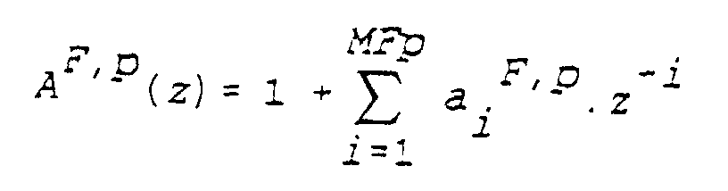 besitzt,
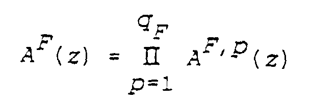 gefilterten Eingangssignal (sp-1(n)) der Stufe p des qB-stufigen Vorgangs gebildet ist, wobei der zweite Bestandteil des Kurzzeitsynthesefilters (16) eine Übertragungsfunktion der Form 1/AB(z) mit
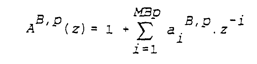 besitzt und das Kurzzeitsynthesefilter (16) eine übertragungsfunktion der Form 1/A(z) mit A(z) = AF(z)·AB(z) besitzt.
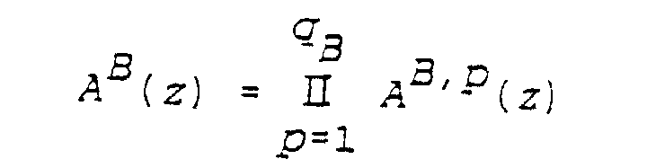
- Codierverfahren nach Anspruch 17, dadurch gekennzeichnet, daß zumindest einige der Anregungsparameter bestimmt werden, indem die Energie eines Fehlersignals minimiert wird, welches aus der Filterung der Differenz zwischen dem ersten Tonfrequenzsignal (s(n)) und dem Synthesesignal (s and(n)) mittels mindestens eines Wahrnehmungswichtungsfilters (38) resultiert, dessen Übertragungsfunktion die Form W(z)=A(z/γ1)/A(z/γ2) besitzt, wobei γ1 und γ2 spektrale Ausdehnungskoeffizienten bezeichnen, für die 0 ≤ γ2 ≤ γ1 ≤ 1 gilt.
- Codierverfahren nach Anspruch 17, dadurch gekennzeichnet, daß zumindest einige der Anregungsparameter bestimmt werden, indem die Energie eines Fehlersignals minimiert wird, welches aus der Filterung der Differenz zwischen dem ersten Tonfrequenzsignal (s(n)) und dem Synthesesignal (s and(n)) mittels mindestens eines Wahrnehmungswichtungsfilters (38) resultiert, dessen Übertragungsfunktion die Formbesitzt, wobei γ1 F,p, γ2 F,p Paare von spektralen Ausdehnungskoeffizienten bezeichnen, für die 0 ≤ γ2 F,p ≤ γ1 F,p ≤ 1 für 1 ≤ p ≤ qF gilt, und γ1 B,p, γ2 B,p Paare von spektralen Ausdehnungskoeffizienten bezeichnen, für die 0 ≤ γ2 B,p ≤ γ1 B,p ≤ 1 für 1 ≤ p ≤ qB gilt.
- Verfahren zur Decodierung eines binären Stroms zur Erzeugung eines durch den binären Strom codierten Tonfrequenzsignals in aufeinanderfolgenden Blöcken,
dadurch gekennzeichnet, daß man:Quantisierungswerte von Parametern (LPC/F), welche einen ersten Bestandteil eines Kurzzeitsynthesefilters (16) definieren, und von Anregungsparametern (k, β, LTP) erhält, wobei die den ersten Bestandteil des Kurzzeitsynthesefilters definierenden Parameter eine Zahl qF, die wenigstens gleich 1 ist, von Sätzen von linearen Prädiktionskoeffizienten a1 F,p,..., aMFp F,p für 1 ≤ p ≤ qF repräsentieren, wobei jeder Satz p eine im voraus festgelegte Zahl MFp von Koeffizienten umfaßt, wobei der erste Bestandteil des Kurzzeitsynthesefilters (16) eine Übertragungsfunktion der Form 1/AF(z) mitbesitzt,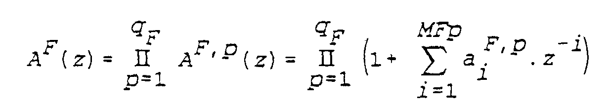 auf Grundlage der Quantisierungswerte der Anregungsparameter ein Anregungssignal (u(n)) erzeugt,ein synthetisiertes Tonfrequenzsignal (s and(n)) erzeugt, indem das Anregungssignal mittels eines Kurzzeitsynthesefilters (16) der Übertragungsfunktion 1/A(z) mit A(z) = AF(z)·AB(z), gefiltert wird, wobei 1/AB(z) die Übertragungsfunktion eines zweiten Bestandteils des Kurzzeitsynthesefilters (16) repräsentiert,das synthetisierte Signal (s and(n)) mittels eines Filters der Übertragungsfunktion AF(z) filtert undeine Analyse des gefilterten synthetisierten Signals (s and0(n)) durch lineare Prädiktion durchführt, um für mindestens einen nachfolgenden Block Koeffizienten des zweiten Bestandteils des Kurzzeitsynthesefilters (16) zu erhalten, und daß die Analyse des gefilterten synthetisierten Signals durch lineare Prädiktion ein Vorgang in qB aufeinanderfolgenden Stufen (5p) ist, wobei qB eine ganze Zahl ist, die wenigstens gleich 1 ist, wobei dieser Vorgang in jeder Prädiktionsstufe p (1 ≤ p ≤ qB) die Bestimmung von Parametern umfaßt, welche eine für die jeweilige Stufe p im voraus festgelegte Zahl MBp von linearen Prädiktionskoeffizienten a1 B,p,..., aMBp B,p eines Eingangssignals der Stufe repräsentieren, wobei das gefilterte synthetisierte Signal (s and0(n)) das Eingangssignal (s0(n)) der ersten Stufe bildet und das Eingangssignal (sp(n)) einer Stufe p+1 von dem mittels eines Filters der Übertragungsfunktiongefilterten Eingangssignal (sp-1(n)) der Stufe p gebildet ist, wobei der zweite Bestandteil des Kurzzeitsynthesefilters (16) eine Übertragungsfunktion der Form 1/AB(z) mit
 besitzt.
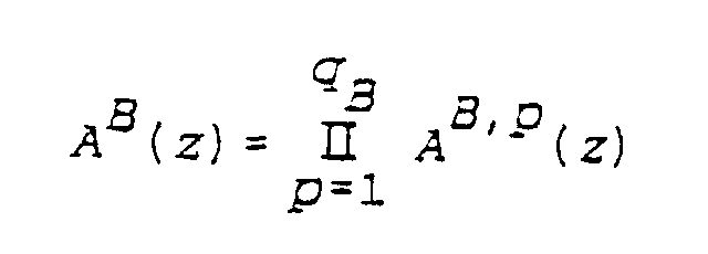
- Decodierverfahren nach Anspruch 20, dadurch gekennzeichnet, daß das synthetisierte Tonfrequenzsignal (s and(n)) an ein Nachfilter (17) angelegt wird, dessen Übertragungsfunktion (HPF(z)) einen Term der Form A(z/β1)/A(z/β2) umfaßt, wobei β1 und β2 Koeffizienten bezeichnen, für die 0 ≤ β1 ≤ β2 ≤ 1 gilt.
- Decodierverfahren nach Anspruch 20, dadurch gekennzeichnet, daß das synthetisierte Tonfrequenzsignal (s and(n)) an ein Nachfilter (17) angelegt wird, dessen Übertragungsfunktion (HPF(z)) einen Term der Formbesitzt, wobei β1 F,p, β2 F,p Paare von Koeffizienten bezeichnen, für die 0 ≤ β1 F,p ≤ β2 F,p ≤ 1 für 1 ≤ p ≤ qF gilt, und β1 B,p, β2 B,p Paare von Koeffizienten bezeichnen, für die 0 ≤ β1 B,p ≤ β2 B,p ≤ 1 für 1 ≤ p ≤ qB gilt.

Applications Claiming Priority (2)
| Application Number | Priority Date | Filing Date | Title |
|---|---|---|---|
| FR9514925 | 1995-12-15 | ||
| FR9514925A FR2742568B1 (fr) | 1995-12-15 | 1995-12-15 | Procede d'analyse par prediction lineaire d'un signal audiofrequence, et procedes de codage et de decodage d'un signal audiofrequence en comportant application |
Publications (2)
| Publication Number | Publication Date |
|---|---|
| EP0782128A1 EP0782128A1 (de) | 1997-07-02 |
| EP0782128B1 true EP0782128B1 (de) | 2000-06-21 |
Family
ID=9485565
Family Applications (1)
| Application Number | Title | Priority Date | Filing Date |
|---|---|---|---|
| EP96402715A Expired - Lifetime EP0782128B1 (de) | 1995-12-15 | 1996-12-12 | Verfahren zur Analyse eines Audiofrequenzsignals durch lineare Prädiktion, und Anwendung auf ein Verfahren zur Kodierung und Dekodierung eines Audiofrequenzsignals |
Country Status (7)
| Country | Link |
|---|---|
| US (1) | US5787390A (de) |
| EP (1) | EP0782128B1 (de) |
| JP (1) | JP3678519B2 (de) |
| KR (1) | KR100421226B1 (de) |
| CN (1) | CN1159691A (de) |
| DE (1) | DE69608947T2 (de) |
| FR (1) | FR2742568B1 (de) |
Families Citing this family (47)
| Publication number | Priority date | Publication date | Assignee | Title |
|---|---|---|---|---|
| US5621852A (en) * | 1993-12-14 | 1997-04-15 | Interdigital Technology Corporation | Efficient codebook structure for code excited linear prediction coding |
| FR2729247A1 (fr) * | 1995-01-06 | 1996-07-12 | Matra Communication | Procede de codage de parole a analyse par synthese |
| FR2729246A1 (fr) * | 1995-01-06 | 1996-07-12 | Matra Communication | Procede de codage de parole a analyse par synthese |
| JPH10124088A (ja) * | 1996-10-24 | 1998-05-15 | Sony Corp | 音声帯域幅拡張装置及び方法 |
| JP3064947B2 (ja) | 1997-03-26 | 2000-07-12 | 日本電気株式会社 | 音声・楽音符号化及び復号化装置 |
| FI973873A (fi) * | 1997-10-02 | 1999-04-03 | Nokia Mobile Phones Ltd | Puhekoodaus |
| FR2774827B1 (fr) | 1998-02-06 | 2000-04-14 | France Telecom | Procede de decodage d'un flux binaire representatif d'un signal audio |
| US6223157B1 (en) * | 1998-05-07 | 2001-04-24 | Dsc Telecom, L.P. | Method for direct recognition of encoded speech data |
| US6148283A (en) * | 1998-09-23 | 2000-11-14 | Qualcomm Inc. | Method and apparatus using multi-path multi-stage vector quantizer |
| US6778953B1 (en) * | 2000-06-02 | 2004-08-17 | Agere Systems Inc. | Method and apparatus for representing masked thresholds in a perceptual audio coder |
| KR100865860B1 (ko) * | 2000-11-09 | 2008-10-29 | 코닌클리케 필립스 일렉트로닉스 엔.브이. | 보다 높은 지각의 품질을 위한 전화 음성의 광대역 확장 |
| CN1270291C (zh) * | 2000-12-06 | 2006-08-16 | 皇家菲利浦电子有限公司 | 滤波设备和方法 |
| WO2002067246A1 (en) * | 2001-02-16 | 2002-08-29 | Centre For Signal Processing, Nanyang Technological University | Method for determining optimum linear prediction coefficients |
| US6590972B1 (en) * | 2001-03-15 | 2003-07-08 | 3Com Corporation | DTMF detection based on LPC coefficients |
| US7062429B2 (en) * | 2001-09-07 | 2006-06-13 | Agere Systems Inc. | Distortion-based method and apparatus for buffer control in a communication system |
| US7240001B2 (en) * | 2001-12-14 | 2007-07-03 | Microsoft Corporation | Quality improvement techniques in an audio encoder |
| US6934677B2 (en) | 2001-12-14 | 2005-08-23 | Microsoft Corporation | Quantization matrices based on critical band pattern information for digital audio wherein quantization bands differ from critical bands |
| US20030216921A1 (en) * | 2002-05-16 | 2003-11-20 | Jianghua Bao | Method and system for limited domain text to speech (TTS) processing |
| EP1383109A1 (de) * | 2002-07-17 | 2004-01-21 | STMicroelectronics N.V. | Verfahren und Vorrichtung für breitbandige Sprachkodierung |
| JP4676140B2 (ja) * | 2002-09-04 | 2011-04-27 | マイクロソフト コーポレーション | オーディオの量子化および逆量子化 |
| US7299190B2 (en) * | 2002-09-04 | 2007-11-20 | Microsoft Corporation | Quantization and inverse quantization for audio |
| US7502743B2 (en) * | 2002-09-04 | 2009-03-10 | Microsoft Corporation | Multi-channel audio encoding and decoding with multi-channel transform selection |
| US7254533B1 (en) * | 2002-10-17 | 2007-08-07 | Dilithium Networks Pty Ltd. | Method and apparatus for a thin CELP voice codec |
| US20040260540A1 (en) * | 2003-06-20 | 2004-12-23 | Tong Zhang | System and method for spectrogram analysis of an audio signal |
| US7539612B2 (en) * | 2005-07-15 | 2009-05-26 | Microsoft Corporation | Coding and decoding scale factor information |
| US8027242B2 (en) | 2005-10-21 | 2011-09-27 | Qualcomm Incorporated | Signal coding and decoding based on spectral dynamics |
| US8417185B2 (en) * | 2005-12-16 | 2013-04-09 | Vocollect, Inc. | Wireless headset and method for robust voice data communication |
| US7773767B2 (en) | 2006-02-06 | 2010-08-10 | Vocollect, Inc. | Headset terminal with rear stability strap |
| US7885419B2 (en) | 2006-02-06 | 2011-02-08 | Vocollect, Inc. | Headset terminal with speech functionality |
| US8392176B2 (en) | 2006-04-10 | 2013-03-05 | Qualcomm Incorporated | Processing of excitation in audio coding and decoding |
| CN101114415B (zh) * | 2006-07-25 | 2011-01-12 | 元太科技工业股份有限公司 | 双稳态显示器的驱动装置及其方法 |
| EP2063418A4 (de) * | 2006-09-15 | 2010-12-15 | Panasonic Corp | Audiocodierungseinrichtung und audiocodierungsverfahren |
| CN101536311B (zh) | 2007-01-25 | 2012-09-26 | 夏普株式会社 | 脉冲输出电路、使用该脉冲输出电路的显示装置的驱动电路、显示装置及脉冲输出方法 |
| US8428957B2 (en) | 2007-08-24 | 2013-04-23 | Qualcomm Incorporated | Spectral noise shaping in audio coding based on spectral dynamics in frequency sub-bands |
| TWI346465B (en) * | 2007-09-04 | 2011-08-01 | Univ Nat Central | Configurable common filterbank processor applicable for various audio video standards and processing method thereof |
| USD605629S1 (en) | 2008-09-29 | 2009-12-08 | Vocollect, Inc. | Headset |
| FR2938688A1 (fr) | 2008-11-18 | 2010-05-21 | France Telecom | Codage avec mise en forme du bruit dans un codeur hierarchique |
| KR101397512B1 (ko) * | 2009-03-11 | 2014-05-22 | 후아웨이 테크놀러지 컴퍼니 리미티드 | 선형 예측 코딩 분석을 위한 방법, 장치 및 시스템 |
| US8160287B2 (en) | 2009-05-22 | 2012-04-17 | Vocollect, Inc. | Headset with adjustable headband |
| US8438659B2 (en) | 2009-11-05 | 2013-05-07 | Vocollect, Inc. | Portable computing device and headset interface |
| CN102812512B (zh) * | 2010-03-23 | 2014-06-25 | Lg电子株式会社 | 处理音频信号的方法和装置 |
| KR101257776B1 (ko) * | 2011-10-06 | 2013-04-24 | 단국대학교 산학협력단 | 상태-체크 코드를 이용한 부호화 방법 및 부호화 장치 |
| CN102638846B (zh) * | 2012-03-28 | 2015-08-19 | 浙江大学 | 一种基于最优量化策略的wsn通信负载降低方法 |
| CN110415715B (zh) * | 2014-01-24 | 2022-11-25 | 日本电信电话株式会社 | 线性预测分析装置、线性预测分析方法以及记录介质 |
| ES2713027T3 (es) * | 2014-01-24 | 2019-05-17 | Nippon Telegraph & Telephone | Aparato, método, programa y soporte de registro de análisis predictivo lineal |
| US9583115B2 (en) * | 2014-06-26 | 2017-02-28 | Qualcomm Incorporated | Temporal gain adjustment based on high-band signal characteristic |
| US10542289B2 (en) * | 2015-07-16 | 2020-01-21 | Dolby Laboratories Licensing Corporation | Signal reshaping and coding for HDR and wide color gamut signals |
Family Cites Families (11)
| Publication number | Priority date | Publication date | Assignee | Title |
|---|---|---|---|---|
| US3975587A (en) * | 1974-09-13 | 1976-08-17 | International Telephone And Telegraph Corporation | Digital vocoder |
| US4398262A (en) * | 1981-12-22 | 1983-08-09 | Motorola, Inc. | Time multiplexed n-ordered digital filter |
| CA1245363A (en) * | 1985-03-20 | 1988-11-22 | Tetsu Taguchi | Pattern matching vocoder |
| US4868867A (en) * | 1987-04-06 | 1989-09-19 | Voicecraft Inc. | Vector excitation speech or audio coder for transmission or storage |
| JP2625998B2 (ja) * | 1988-12-09 | 1997-07-02 | 沖電気工業株式会社 | 特徴抽出方式 |
| GB2235354A (en) * | 1989-08-16 | 1991-02-27 | Philips Electronic Associated | Speech coding/encoding using celp |
| US5307441A (en) * | 1989-11-29 | 1994-04-26 | Comsat Corporation | Wear-toll quality 4.8 kbps speech codec |
| FI98104C (fi) * | 1991-05-20 | 1997-04-10 | Nokia Mobile Phones Ltd | Menetelmä herätevektorin generoimiseksi ja digitaalinen puhekooderi |
| IT1257065B (it) * | 1992-07-31 | 1996-01-05 | Sip | Codificatore a basso ritardo per segnali audio, utilizzante tecniche di analisi per sintesi. |
| US5706395A (en) * | 1995-04-19 | 1998-01-06 | Texas Instruments Incorporated | Adaptive weiner filtering using a dynamic suppression factor |
| US5692101A (en) * | 1995-11-20 | 1997-11-25 | Motorola, Inc. | Speech coding method and apparatus using mean squared error modifier for selected speech coder parameters using VSELP techniques |
-
1995
- 1995-12-15 FR FR9514925A patent/FR2742568B1/fr not_active Expired - Lifetime
-
1996
- 1996-12-11 US US08/763,457 patent/US5787390A/en not_active Expired - Lifetime
- 1996-12-12 EP EP96402715A patent/EP0782128B1/de not_active Expired - Lifetime
- 1996-12-12 DE DE69608947T patent/DE69608947T2/de not_active Expired - Lifetime
- 1996-12-13 CN CN96121556A patent/CN1159691A/zh active Pending
- 1996-12-14 KR KR1019960065696A patent/KR100421226B1/ko active IP Right Grant
- 1996-12-16 JP JP33614096A patent/JP3678519B2/ja not_active Expired - Lifetime
Also Published As
| Publication number | Publication date |
|---|---|
| JPH09212199A (ja) | 1997-08-15 |
| DE69608947T2 (de) | 2001-02-01 |
| US5787390A (en) | 1998-07-28 |
| KR970050107A (ko) | 1997-07-29 |
| EP0782128A1 (de) | 1997-07-02 |
| FR2742568B1 (fr) | 1998-02-13 |
| CN1159691A (zh) | 1997-09-17 |
| DE69608947D1 (de) | 2000-07-27 |
| FR2742568A1 (fr) | 1997-06-20 |
| KR100421226B1 (ko) | 2004-07-19 |
| JP3678519B2 (ja) | 2005-08-03 |
Similar Documents
| Publication | Publication Date | Title |
|---|---|---|
| EP0782128B1 (de) | Verfahren zur Analyse eines Audiofrequenzsignals durch lineare Prädiktion, und Anwendung auf ein Verfahren zur Kodierung und Dekodierung eines Audiofrequenzsignals | |
| EP0801790B1 (de) | Verfahren zur sprachkodierung mittels analyse durch synthese | |
| FR2734389A1 (fr) | Procede d'adaptation du niveau de masquage du bruit dans un codeur de parole a analyse par synthese utilisant un filtre de ponderation perceptuelle a court terme | |
| EP1692689B1 (de) | Optimiertes mehrfach-codierungsverfahren | |
| EP0721180B1 (de) | Sprachkodierung mittels Analyse durch Synthese | |
| WO1996021218A1 (fr) | Procede de codage de parole a analyse par synthese | |
| JP3357795B2 (ja) | 音声符号化方法および装置 | |
| EP0616315A1 (de) | Vorrichtung zur digitalen Sprachkodierung und -dekodierung, Verfahren zum Durchsuchen eines pseudologarithmischen LTP-Verzögerungskodebuchs und Verfahren zur LTP-Analyse | |
| EP2171713B1 (de) | Kodierung digitaler audiosignale | |
| FR2783651A1 (fr) | Dispositif et procede de filtrage d'un signal de parole, recepteur et systeme de communications telephonique | |
| EP1192619B1 (de) | Audio-kodierung, dekodierung zur interpolation | |
| EP1192618B1 (de) | Audiokodierung mit adaptiver lifterung | |
| EP1192621B1 (de) | Audiokodierung mit harmonischen komponenten | |
| EP1194923B1 (de) | Verfahren und system für audio analyse und synthese | |
| WO2001003121A1 (fr) | Codage et decodage audio avec composants harmoniques et phase minimale | |
| WO2013135997A1 (fr) | Modification des caractéristiques spectrales d'un filtre de prédiction linéaire d'un signal audionumérique représenté par ses coefficients lsf ou isf | |
| EP1192620A1 (de) | Audiosignalkodierer und -dekodierer einschliesslich nicht-harmonischen komponenten | |
| WO2002029786A1 (fr) | Procede et dispositif de codage segmental d'un signal audio | |
| FR2980620A1 (fr) | Traitement d'amelioration de la qualite des signaux audiofrequences decodes | |
| FR2773653A1 (fr) | Dispositifs de codage/decodage de donnees, et supports d'enregistrement memorisant un programme de codage/decodage de donnees au moyen d'un filtre de ponderation frequentielle | |
| FR2737360A1 (fr) | Procedes de codage et de decodage de signaux audiofrequence, codeur et decodeur pour la mise en oeuvre de tels procedes |
Legal Events
| Date | Code | Title | Description |
|---|---|---|---|
| PUAI | Public reference made under article 153(3) epc to a published international application that has entered the european phase |
Free format text: ORIGINAL CODE: 0009012 |
|
| AK | Designated contracting states |
Kind code of ref document: A1 Designated state(s): DE GB IT |
|
| 17P | Request for examination filed |
Effective date: 19970726 |
|
| 17Q | First examination report despatched |
Effective date: 19990511 |
|
| GRAG | Despatch of communication of intention to grant |
Free format text: ORIGINAL CODE: EPIDOS AGRA |
|
| GRAG | Despatch of communication of intention to grant |
Free format text: ORIGINAL CODE: EPIDOS AGRA |
|
| GRAH | Despatch of communication of intention to grant a patent |
Free format text: ORIGINAL CODE: EPIDOS IGRA |
|
| RIC1 | Information provided on ipc code assigned before grant |
Free format text: 7G 10L 19/06 A |
|
| GRAH | Despatch of communication of intention to grant a patent |
Free format text: ORIGINAL CODE: EPIDOS IGRA |
|
| GRAA | (expected) grant |
Free format text: ORIGINAL CODE: 0009210 |
|
| AK | Designated contracting states |
Kind code of ref document: B1 Designated state(s): DE GB IT |
|
| REF | Corresponds to: |
Ref document number: 69608947 Country of ref document: DE Date of ref document: 20000727 |
|
| ITF | It: translation for a ep patent filed |
Owner name: BARZANO' E ZANARDO MILANO S.P.A. |
|
| GBT | Gb: translation of ep patent filed (gb section 77(6)(a)/1977) |
Effective date: 20000821 |
|
| PLBE | No opposition filed within time limit |
Free format text: ORIGINAL CODE: 0009261 |
|
| STAA | Information on the status of an ep patent application or granted ep patent |
Free format text: STATUS: NO OPPOSITION FILED WITHIN TIME LIMIT |
|
| 26N | No opposition filed | ||
| REG | Reference to a national code |
Ref country code: GB Ref legal event code: IF02 |
|
| PGFP | Annual fee paid to national office [announced via postgrant information from national office to epo] |
Ref country code: IT Payment date: 20151120 Year of fee payment: 20 Ref country code: DE Payment date: 20151119 Year of fee payment: 20 Ref country code: GB Payment date: 20151125 Year of fee payment: 20 |
|
| REG | Reference to a national code |
Ref country code: DE Ref legal event code: R082 Ref document number: 69608947 Country of ref document: DE Representative=s name: WEICKMANN & WEICKMANN PATENTANWAELTE - RECHTSA, DE Ref country code: DE Ref legal event code: R081 Ref document number: 69608947 Country of ref document: DE Owner name: 3G LICENSING S.A., LU Free format text: FORMER OWNER: FRANCE TELECOM, S.A., PARIS, FR Ref country code: DE Ref legal event code: R081 Ref document number: 69608947 Country of ref document: DE Owner name: ORANGE, FR Free format text: FORMER OWNER: FRANCE TELECOM, S.A., PARIS, FR |
|
| REG | Reference to a national code |
Ref country code: DE Ref legal event code: R082 Ref document number: 69608947 Country of ref document: DE Representative=s name: WEICKMANN & WEICKMANN PATENTANWAELTE - RECHTSA, DE Ref country code: DE Ref legal event code: R081 Ref document number: 69608947 Country of ref document: DE Owner name: 3G LICENSING S.A., LU Free format text: FORMER OWNER: ORANGE, PARIS, FR |
|
| REG | Reference to a national code |
Ref country code: DE Ref legal event code: R071 Ref document number: 69608947 Country of ref document: DE |
|
| REG | Reference to a national code |
Ref country code: GB Ref legal event code: PE20 Expiry date: 20161211 |
|
| PG25 | Lapsed in a contracting state [announced via postgrant information from national office to epo] |
Ref country code: GB Free format text: LAPSE BECAUSE OF EXPIRATION OF PROTECTION Effective date: 20161211 |