EP1194923B1 - Verfahren und system für audio analyse und synthese - Google Patents
Verfahren und system für audio analyse und synthese Download PDFInfo
- Publication number
- EP1194923B1 EP1194923B1 EP00953223A EP00953223A EP1194923B1 EP 1194923 B1 EP1194923 B1 EP 1194923B1 EP 00953223 A EP00953223 A EP 00953223A EP 00953223 A EP00953223 A EP 00953223A EP 1194923 B1 EP1194923 B1 EP 1194923B1
- Authority
- EP
- European Patent Office
- Prior art keywords
- frames
- samples
- module
- synthesis
- audio signal
- Prior art date
- Legal status (The legal status is an assumption and is not a legal conclusion. Google has not performed a legal analysis and makes no representation as to the accuracy of the status listed.)
- Expired - Lifetime
Links
- 230000015572 biosynthetic process Effects 0.000 title claims abstract description 61
- 238000003786 synthesis reaction Methods 0.000 title claims abstract description 58
- 238000004458 analytical method Methods 0.000 title claims abstract description 46
- 238000000034 method Methods 0.000 title claims abstract description 42
- 238000001228 spectrum Methods 0.000 claims abstract description 58
- 230000005236 sound signal Effects 0.000 claims abstract description 48
- 238000012545 processing Methods 0.000 claims abstract description 16
- 230000001131 transforming effect Effects 0.000 claims abstract description 7
- 230000003595 spectral effect Effects 0.000 claims description 60
- 238000000605 extraction Methods 0.000 claims description 12
- 230000005540 biological transmission Effects 0.000 claims description 7
- 230000002194 synthesizing effect Effects 0.000 claims description 7
- 238000002407 reforming Methods 0.000 abstract 1
- 239000013598 vector Substances 0.000 description 62
- 238000013139 quantization Methods 0.000 description 37
- 230000006870 function Effects 0.000 description 18
- 238000010586 diagram Methods 0.000 description 11
- 230000006835 compression Effects 0.000 description 9
- 238000007906 compression Methods 0.000 description 9
- 230000006837 decompression Effects 0.000 description 9
- 230000009466 transformation Effects 0.000 description 8
- 238000004364 calculation method Methods 0.000 description 7
- 230000006978 adaptation Effects 0.000 description 6
- 238000009499 grossing Methods 0.000 description 6
- 238000010606 normalization Methods 0.000 description 6
- 239000002131 composite material Substances 0.000 description 5
- 238000012886 linear function Methods 0.000 description 5
- 230000008569 process Effects 0.000 description 5
- 238000005070 sampling Methods 0.000 description 5
- 238000001308 synthesis method Methods 0.000 description 5
- 230000002123 temporal effect Effects 0.000 description 5
- 102100032077 Neuronal calcium sensor 1 Human genes 0.000 description 4
- 101710133725 Neuronal calcium sensor 1 Proteins 0.000 description 4
- 230000000873 masking effect Effects 0.000 description 4
- 238000002156 mixing Methods 0.000 description 4
- 238000012360 testing method Methods 0.000 description 4
- 101100129500 Caenorhabditis elegans max-2 gene Proteins 0.000 description 3
- 101100083446 Danio rerio plekhh1 gene Proteins 0.000 description 3
- 239000000284 extract Substances 0.000 description 3
- 238000012986 modification Methods 0.000 description 3
- 230000004048 modification Effects 0.000 description 3
- 238000011002 quantification Methods 0.000 description 3
- 101100459912 Caenorhabditis elegans ncs-1 gene Proteins 0.000 description 2
- 101000822695 Clostridium perfringens (strain 13 / Type A) Small, acid-soluble spore protein C1 Proteins 0.000 description 2
- 101000655262 Clostridium perfringens (strain 13 / Type A) Small, acid-soluble spore protein C2 Proteins 0.000 description 2
- 101000655256 Paraclostridium bifermentans Small, acid-soluble spore protein alpha Proteins 0.000 description 2
- 101000655264 Paraclostridium bifermentans Small, acid-soluble spore protein beta Proteins 0.000 description 2
- 230000008901 benefit Effects 0.000 description 2
- 238000001514 detection method Methods 0.000 description 2
- 239000006185 dispersion Substances 0.000 description 2
- 238000001914 filtration Methods 0.000 description 2
- 238000012546 transfer Methods 0.000 description 2
- PXFBZOLANLWPMH-UHFFFAOYSA-N 16-Epiaffinine Natural products C1C(C2=CC=CC=C2N2)=C2C(=O)CC2C(=CC)CN(C)C1C2CO PXFBZOLANLWPMH-UHFFFAOYSA-N 0.000 description 1
- 101100459896 Caenorhabditis elegans ncl-1 gene Proteins 0.000 description 1
- 238000013459 approach Methods 0.000 description 1
- 238000005311 autocorrelation function Methods 0.000 description 1
- 238000004061 bleaching Methods 0.000 description 1
- 230000008859 change Effects 0.000 description 1
- 238000006243 chemical reaction Methods 0.000 description 1
- 238000004891 communication Methods 0.000 description 1
- 238000007796 conventional method Methods 0.000 description 1
- 238000012937 correction Methods 0.000 description 1
- 230000003111 delayed effect Effects 0.000 description 1
- 230000001419 dependent effect Effects 0.000 description 1
- 230000000694 effects Effects 0.000 description 1
- 210000004704 glottis Anatomy 0.000 description 1
- 238000003780 insertion Methods 0.000 description 1
- 230000037431 insertion Effects 0.000 description 1
- 238000005457 optimization Methods 0.000 description 1
- 230000008520 organization Effects 0.000 description 1
- 230000000717 retained effect Effects 0.000 description 1
- 230000011218 segmentation Effects 0.000 description 1
- 238000010183 spectrum analysis Methods 0.000 description 1
- 238000011282 treatment Methods 0.000 description 1
Images


Classifications
-
- G—PHYSICS
- G10—MUSICAL INSTRUMENTS; ACOUSTICS
- G10L—SPEECH ANALYSIS TECHNIQUES OR SPEECH SYNTHESIS; SPEECH RECOGNITION; SPEECH OR VOICE PROCESSING TECHNIQUES; SPEECH OR AUDIO CODING OR DECODING
- G10L19/00—Speech or audio signals analysis-synthesis techniques for redundancy reduction, e.g. in vocoders; Coding or decoding of speech or audio signals, using source filter models or psychoacoustic analysis
- G10L19/02—Speech or audio signals analysis-synthesis techniques for redundancy reduction, e.g. in vocoders; Coding or decoding of speech or audio signals, using source filter models or psychoacoustic analysis using spectral analysis, e.g. transform vocoders or subband vocoders
-
- G—PHYSICS
- G10—MUSICAL INSTRUMENTS; ACOUSTICS
- G10L—SPEECH ANALYSIS TECHNIQUES OR SPEECH SYNTHESIS; SPEECH RECOGNITION; SPEECH OR VOICE PROCESSING TECHNIQUES; SPEECH OR AUDIO CODING OR DECODING
- G10L19/00—Speech or audio signals analysis-synthesis techniques for redundancy reduction, e.g. in vocoders; Coding or decoding of speech or audio signals, using source filter models or psychoacoustic analysis
- G10L19/04—Speech or audio signals analysis-synthesis techniques for redundancy reduction, e.g. in vocoders; Coding or decoding of speech or audio signals, using source filter models or psychoacoustic analysis using predictive techniques
- G10L19/08—Determination or coding of the excitation function; Determination or coding of the long-term prediction parameters
- G10L19/10—Determination or coding of the excitation function; Determination or coding of the long-term prediction parameters the excitation function being a multipulse excitation
Definitions
- the present invention relates to the analysis and synthesis of audio signals from representations of these signals in the spectral domain.
- the signal spectrum is obtained by transforming successive frames to the frequency domain.
- the transformation used is most often Fast Fourier Transform (FFT); but other known transforms are usable.
- FFT Fast Fourier Transform
- the number N of samples per frame is typically of the order of 100 to 500, which represents frames of a few tens of milliseconds.
- the TFR is performed on 2N points, N samples being zero added to the N samples of the frame.
- the spectrum obtained by Fourier transform of the signal frame is the convolution of the real spectrum of the signal by the Fourier transform of the signal analysis window.
- This analysis window which weights the samples of each frame, is necessary to take into account the finite duration of the frame. If the signal frame is directly subjected to the TFR, that is to say if a rectangular analysis window is used, the spectrum obtained is disturbed by the secondary peaks of the TFR of the analysis window.
- windows having better spectral properties that is to say, weighting functions whose support is limited to N samples and whose Fourier transform has its energy concentrated in a narrow peak with a strong attenuation of the secondary peaks. The most common of these windows are the Hamming, Hanning and Kaiser windows.
- US-A-5,878,388 relates to a method of analyzing and synthesizing the voice.
- US-A-5,911,130 relates to compression and decompression of audio signal.
- WOLA Weighted OLA
- An object of the invention is to provide a diagram for analyzing and synthesizing audio signals that makes it possible to limit the rate of the analysis frames, while using analysis windows having good spectral properties.
- the invention proposes a method for analyzing an audio signal processed by successive frames of N samples, in which the samples of each frame are weighted by an analysis window of Hamming, Hanning, Kaiser or similar type, and a calculation is made.
- spectrum of the audio signal by transforming each frame of weighted samples in the frequency domain, and processing the spectrum of the audio signal to output synthesis parameters of a signal derived from the analyzed audio signal.
- the successive frames comprise an alternation of frames for which complete sets of synthesis parameters are provided, which have mutual overlays of less than N / 2 samples, ie less than 50%, and frames for which delivers incomplete sets of synthesis parameters.
- Frames for which complete sets of synthesis parameters are not delivered may not be spectrally analyzed. Alternatively, an analysis can nevertheless be performed for these frames, so delivering incomplete sets of synthesis parameters including data representing an interpolation error of at least one of the synthesis parameters and / or data representing an interpolation filter of at least one of the synthesis parameters.
- the processing of the spectrum of the audio signal comprises an extraction of coding parameters for the transmission and / or storage of the coded audio signal.
- the processing of the spectrum of the audio signal comprises a denoising by spectral subtraction. Other areas of application can still be considered among the audio treatments.
- a second aspect of the invention relates to a method of synthesis an audio signal, in which a set of successive overlapping fields of N samples of the audio signal weighted by an analysis window is evaluated, by transforming in the time domain spectral estimates respectively corresponding to said frames, and the evaluated frames are combined to form the synthesized signal.
- the spectral estimates are obtained by processing synthesis parameters respectively associated with the frames of said subset while, for the frames not belonging to the subset, the spectral estimates are obtained with a interpolation of at least a part of the synthesis parameters.
- the successive frames of said subset have mutual time offsets of M samples, the number M being greater than N / 2, whereas the successive frames of said set have mutual time offsets of M / p samples, p being an integer plus 1. That each evaluated frame is modified by applying to it a processing corresponding to a division by said analysis window and to a multiplication by a synthesis window, and the synthesized signal is formed as an overlapping sum of the modified frames.
- the invention also proposes audio processing devices comprising means for implementing the methods of analysis and synthesis above.
- the encoder and decoder described below are digital circuits which can, as is customary in the field of audio signal processing, be implemented by programming a digital signal processor (DSP) or an integrated circuit. specific application (ASIC).
- DSP digital signal processor
- ASIC application specific application
- the audio coder shown in FIG. 1 processes an input audio signal x which, in the nonlimiting example considered hereinafter, is a speech signal.
- the signal x is available in digital form, for example at a sampling frequency F e of 8 kHz. It is for example delivered by an analog-digital converter processing the amplified output signal of a microphone.
- the input signal x can also be formed from another version, analog or digital, coded or not, of the speech signal.
- the encoder comprises a module 1 which forms successive audio signal frames for the various processes performed, and an output multiplexer 6 which delivers an output stream ⁇ containing for each frame quantization parameter sets from which a decoder will be able to to synthesize a decoded version of the audio signal.
- Each frame 2 is composed of a number N of consecutive samples of the audio signal x.
- N 256
- the module 1 multiplies the samples of each frame 2 by a windowing function f A , preferably chosen for its good spectral properties.
- a windowing function f A preferably chosen for its good spectral properties.
- f AT ( i ) 1 two ( 1 + cos ( two ⁇ i - ( NOT - 1 ) / two NOT ) ) or a window of Kaiser, of expression: f AT ( i ) I 0 ( ⁇ 1 - ( i - ( NOT - 1 ) / two NOT ) two ) I 0 ( ⁇ ) where ⁇ is a coefficient for example equal to 6, and I 0 (.) denotes the Bessel function of index 0.
- the encoder of FIG. 1 carries out an analysis of the audio signal in the spectral domain. It comprises a module 3 which calculates the Fast Fourier Transform (TFR) of each signal frame.
- TFR Fast Fourier Transform
- the TFR 3 module obtains the spectrum of the signal for each frame whose module and phase are respectively denoted
- a fundamental frequency detector 4 estimates for each signal frame a value of the fundamental frequency F 0 .
- the detector 4 can apply any known method of analyzing the speech signal of the frame to estimate the fundamental frequency F 0 , for example a method based on the autocorrelation function or the AMDF function, possibly preceded by a linear prediction bleaching module.
- the estimation can also be carried out in the spectral domain or in the cepstral domain.
- Another possibility is to evaluate the time intervals between the consecutive breaks of the speech signal attributable to closures of the speaker's glottis occurring during the duration of the frame.
- Well known methods that can be used to detect such micro-breaks are described in the following articles: M.
- the estimated fundamental frequency F 0 is quantized, for example scalar, by a module 5, which supplies the output multiplexer 6 with an iF index for quantizing the fundamental frequency for each frame of the signal.
- the encoder uses cepstral parametric modelings to represent an upper envelope and a lower envelope of the audio signal spectrum.
- the first step of the cepstral transformation consists in applying to the signal spectrum module a spectral compression function, which can be a logarithmic or root function.
- ) in the case of a logarithmic compression or LX ( i )
- the compressed spectrum LX of the audio signal is processed by a module 9 which extracts spectral amplitudes associated with the harmonics of the signal corresponding to the multiples of the estimated fundamental frequency F0. These Amplitudes are then interpolated by a module 10 to obtain a compressed upper envelope denoted LX_sup.
- the spectral compression could similarly be performed after the determination of the amplitudes associated with the harmonics. It could also be done after the interpolation, which would only change the shape of the interpolation functions.
- the module 9 for extracting the maxima takes into account the possible variation of the fundamental frequency on the analysis frame, errors that can be made by the detector 4, as well as inaccuracies related to the discrete nature of the frequency sampling. For this, the search for the amplitudes of the spectral peaks does not consist simply in taking the values LX (i) corresponding to the indices i such that iF e / 2N is the frequency closest to a harmonic frequency kF 0 (k ⁇ 1 ).
- the spectral amplitude selected for a harmonic of order k is a local maximum of the modulus of the spectrum in the vicinity of the frequency kF 0 (this amplitude is obtained directly in compressed form when the spectral compression 8 is performed before the extraction of the maxima 9 ).
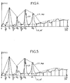
- FIGS. 4 and 5 show an example of the shape of the compressed spectrum LX, where it can be seen that the maximum amplitudes of the harmonic peaks do not necessarily coincide with the amplitudes corresponding to the integer multiples of the estimated fundamental frequency F 0 .
- the flanks of the peaks being rather steep, a small positioning error of the fundamental frequency F 0 , amplified by the harmonic index k, can strongly distort the estimated upper envelope of the spectrum and cause a poor modeling of the formational structure of the signal.
- the interpolation is performed between points whose abscissa is the frequency corresponding to the maximum of the amplitude of a spectral peak, and whose ordinate is this maximum, before or after compression.
- the interpolation performed to calculate the upper envelope LX_sup is a simple linear interpolation.
- Another form of interpolation could be used (for example polynomial or spline).
- the interpolation is performed between points whose abscissa is a frequency kF 0 that is a multiple of the fundamental frequency (in fact the closest frequency in the discrete spectrum) and whose ordinate is the maximum amplitude, before or after compression, of the spectrum in the vicinity of this multiple frequency.
- the width of this search interval depends on the sampling frequency F e , the size 2N of the TFR and the range of possible variation of the fundamental frequency. This width is typically of the order of ten frequencies with the examples of values previously considered. It can be made adjustable according to the value F 0 of the fundamental frequency and the number k of the harmonic.
- a non-linear distortion of the frequency scale is operated on the upper envelope compressed by a module 12 before the module 13 performs the inverse fast Fourier transform (TFRI) providing the Cepstral coefficients cx_sup.
- TFRI inverse fast Fourier transform
- Nonlinear distortion can more effectively minimize the modeling error. It is for example carried out according to a frequency scale of Mel or Bark type. This distortion may possibly depend on the estimated fundamental frequency F 0 .
- the TFRI module 13 needs to compute only a cepstral vector of NCS cepstral coefficients of orders 0 to NCS-1.
- NCS can be equal to 16.
- a post-filtering in the cepstral domain is applied by a module 15 to the compressed upper envelope LX_sup.
- a (z) is the transfer function of a linear prediction filter of the audio signal
- ⁇ 1 and ⁇ 2 are coefficients between 0 and 1
- ⁇ is an optionally zero preemphasis coefficient.
- a normalization module 16 further modifies the cepstral coefficients by imposing the exact modeling constraint of a point of the initial spectrum, which is preferably the most energetic point among the spectral maxima extracted by the module 9 In practice, this normalization only modifies the value of the coefficient p (0).
- the normalization module 16 operates in the following way: it recalculates a value of the spectrum synthesized at the frequency of the maximum indicated by the module 9, by Fourier transform of the truncated and post-lifted cepstral coefficients, taking into account the non-distortion linear of the frequency axis; it determines a gain of normalization g N by the logarithmic difference between the value of the maximum provided by the module 9 and this recalculated value; and he adds the gain g N to the post-lifted cepstral coefficient c p (0). This standardization can be seen as part of post-layering.
- the post-scaled and normalized cepstral coefficients are quantized by a module 18 which transmits corresponding quantization indices icxs to the output multiplexer 6 of the encoder.
- the module 18 can operate by vector quantization from cepstral vectors formed of post-lifted and normalized coefficients, denoted here cx [n] for the n-rank signal frame.
- cx [n] 16 cepstral coefficients cx [n, 0], cx [n, 1], ..., cx [n, NCS-1] is distributed in four sub-groups. cepstral vectors each containing four consecutive order coefficients.
- the cepstral vector cx [n] can be processed by the means represented in FIG. 6, forming part of the quantization module 18.
- cx p [ not , i ] ( 1 - ⁇ ( i ) ) . rcx [ not , i ] + ⁇ ( i ) . rcx [ not - 1 , i ]
- rcx [n] denotes a residual prediction vector for the frame of rank n whose components are respectively denoted rcx [n, 0], rcx [n, 1], ..., rcx [n, NCS-1]
- ⁇ (i) denotes a prediction coefficient chosen to be representative of a supposed inter-frame correlation.
- the numerator of the relation (10) is obtained by a subtractor 20, whose components of the output vector are divided by the quantities 2- ⁇ (i) in 21.
- the residual vector rcx [n] is subdivided into four subvectors, corresponding to the subdivision into four cepstral subvectors.
- the unit 22 proceeds to the vector quantization of each sub-vector of the residual vector rcx [n].
- This quantization can consist, for each sub-vector srcx [n], of selecting in the dictionary the quantized sub-vector srcx_q [n] which minimizes the quadratic error ⁇ srcx [n] -srcx_q [n] ⁇ 2 .
- the set icxs of the quantization index icx, corresponding to the addresses in the dictionaries or dictionaries of the quantized residual sub-vectors srcx_q [n] is supplied to the output multiplexer 6.
- the unit 22 also delivers the values of the quantized residual sub-vectors, which form the vector rcx_q [n]. This latter is delayed by one frame at 23, and its components are multiplied by the coefficients ⁇ (i) at 24 to supply the vector at the negative input of the subtractor 20. This latter vector is, on the other hand, supplied to a adder 25, whose other input receives a vector formed by the components of the quantized residue rcx_q [n] respectively multiplied by the quantities 1- ⁇ (i) at 26. The adder 25 thus delivers the quantized cepstral vector cx_q [n] that will recover the decoder.
- the prediction coefficient ⁇ (i) can be optimized separately for each of the cepstral coefficients.
- the quantization dictionaries can also be optimized separately for each of the four cepstral subvectors.
- a second quantization mode can be provided as well as a process for selecting the one of the two modes that minimizes a least squares criterion with the cepstral coefficients to be quantized, and transmits with the quantization indices of the frame a bit indicating which of the two modes has been selected.
- the adaptation module 29 controls the post-lifter 15 so as to minimize a module difference between the spectrum of the audio signal and the corresponding module values calculated at 28.
- This module difference can be expressed by a sum of absolute values of amplitude differences, compressed or not, corresponding to one or more of the harmonic frequencies. This sum can be weighted according to the spectral amplitudes associated with these frequencies.
- the module difference taken into account in the adaptation of the post-lifts would take into account all the harmonics of the spectrum.
- the module 28 can resynthesize the spectral amplitudes only for one or more multiple frequencies of the fundamental frequency F 0 , selected on the basis of the importance of the absolute value of the spectrum module.
- the adaptation module 29 may for example consider the three most intense spectral peaks in the calculation of the module gap to be minimized.
- the adaptation module 29 estimates a spectral masking curve of the audio signal by means of a psychoacoustic model, and the frequencies taken into account in the calculation of the module deviation to be minimized are selected on the basis of the importance of the modulus of the spectrum relative to the masking curve (for example, the three frequencies for which the spectrum modulus is greater than the masking curve) can be taken.
- Various conventional methods can be used to calculate the masking curve from the audio signal.
- the module 29 can use a filter identification model.
- a simpler method consists in predefining a set of post-scaling parameter sets, that is to say a set of pairs ⁇ 1 , ⁇ 2 in the case of post-scaling according to the relations (8), performing the operations of the modules 15, 16, 18 and 28 for each of these sets of parameters, and retaining that of the sets of parameters which leads to the minimum module gap between the signal spectrum and the recalculated values.
- the quantization indices provided by the module 18 are then those that relate to the best set of parameters.
- the encoder determines coefficients cx_inf representing a compressed lower envelope LX_inf.
- a module 30 extracts from the compressed spectrum LX spectral amplitudes associated with frequencies located in areas of the intermediate spectrum with respect to the multiple frequencies of the estimated fundamental frequency F 0 .
- each amplitude associated with a frequency located in an intermediate zone between two successive harmonics kF 0 and (k + 1) .F 0 simply corresponds to the frequency modulus for the frequency (k + 1/2) .F 0 located in the middle of the interval separating the two harmonics.
- this amplitude could be an average of the spectrum modulus over a small range surrounding this frequency (k + 1/2) .F 0 .
- a module 31 interpolates, for example linear, the spectral amplitudes associated with the frequencies located in the intermediate zones to obtain the compressed lower envelope LX_inf.
- the cepstral transformation applied to this compressed lower envelope LX_inf is performed according to a frequency scale resulting from a nonlinear distortion applied by a module 32.
- the TFRI module 33 calculates a cepstral vector of NCI cepstral coefficients cx_inf of orders 0 to NCl-1 representing the lower envelope.
- the non-linear transformation of the frequency scale for the cepstral transformation of the lower envelope can be performed to a finer scale at high frequencies than at low frequencies, which advantageously makes it possible to model the unvoiced components of the signal at high frequencies.
- the cepstral coefficients cx_inf representing the compressed lower envelope are quantized by a module 34, which can operate in the same way as the module 18 for quantizing the cepstral coefficients representing the compressed upper envelope.
- the vector thus formed is subjected to vector quantization prediction residue, performed by means identical to those shown in Figure 6 but without subdivision into sub-vectors.
- the encoder shown in FIG. 1 does not include any particular device for coding the phases of the harmonic spectrum of the audio signal.
- it includes means 36-40 for encoding temporal information related to the phase of the non-harmonic component represented by the lower envelope.
- a spectral decompression module 36 and a TFRI module 37 form a temporal estimation of the frame of the non-harmonic component.
- the module 36 applies a reciprocal decompression function of the compression function applied by the module 8 (that is to say an exponential or a power function 1 / ⁇ ) to the compressed lower envelope LX_inf produced by the module of interpolation 31. This provides the modulus of the estimated frame of the non-harmonic component, whose phase is taken equal to that ⁇ X of the spectrum of the signal X on the frame.
- the inverse Fourier transform performed by the module 37 provides the estimated frame of the non-harmonic component.
- the module 38 subdivides this estimated frame of the non-harmonic component into several time segments.
- the module 38 calculates the energy equal to the sum of the squares of the samples, and forms a vector E1 formed of eight positive real components equal to the eight calculated energies.
- the largest of these eight energies, denoted EM, is also determined to be provided, with the vector E1, to a normalization module 39.
- This module divides each component of the vector E1 by EM, so that the standardized vector Emix is composed of eight components between 0 and 1. It is this normalized vector Emix, or weighting vector, which is subjected to quantization by the module 40.
- the latter can operate a vector quantization with a determined dictionary at a time. prior learning.
- the quantization index iEm is provided by the module 40 to the output multiplexer 6 of the encoder.
- FIG. 7 shows an alternative embodiment of the means employed by the coder of FIG. 1 for determining the energy-weighting Emix vector of the frame of the non-harmonic component.
- the spectral decompression modules 36, 37 and TFRI operate as those having the same references in FIG. 1.
- a selection module 42 is added to determine the value of the spectrum module subjected to the inverse Fourier transform 37. Based on the estimated fundamental frequency F 0 , the module 42 identifies harmonic regions and non-harmonic regions of the audio signal spectrum. For example, a frequency will be considered as belonging to a harmonic region if it is in a frequency interval centered on a harmonic kF 0 and of width corresponding to a synthesized spectral line width, and to a non-harmonic region otherwise.
- the complex signal subjected to the TFRI 37 is equal to the value of the spectrum, that is to say that its modulus and its phase correspond to the values
- this complex signal has the same phase ⁇ X as the spectrum and a modulus given by the lower envelope after spectral decompression 36. This procedure according to FIG. provides a more accurate modeling of non-harmonic regions.
- the decoder shown in FIG. 8 comprises a demultiplexer input 45 which extracts from the bit stream ⁇ , coming from an encoder according to FIG. 1, the indices iF, icxs, icxi, iEm of quantization of the fundamental frequency F 0 , cepstral coefficients representing the compressed upper envelope, coefficients representing the compressed lower envelope, and the Emix weighting vector, and distributes them respectively to modules 46, 47, 48 and 49.
- These modules 46-49 comprise quantization dictionaries similar to those of the modules 5, 18, 34 and 40 of Figure 1, in order to restore the values of the quantized parameters.
- the modules 47 and 48 have dictionaries for forming the quantized prediction residues rcx_q [n], and they deduce therefrom the quantified cepstral vectors cx_q [n] with elements identical to the elements 23-26 of FIG. 6. These quantified cepstral vectors cx_q [n] provide the cepstral coefficients cx_sup_q and cx_inf_q processed by the decoder.
- a module 51 calculates the fast Fourier transform of the cepstral coefficients cx_sup for each signal frame.
- the frequency scale of the resulting compressed spectrum is modified non-linearly by a module 52 applying the reciprocal non-linear transformation of that of the module 12 of FIG. 1, and which provides the LX_sup estimate of the compressed upper envelope.
- a spectral decompression of LX_sup operated by a module 53, provides the upper envelope X_sup comprising the estimated values of the multi-frequency spectrum module of the fundamental frequency F 0 .
- the module 54 synthesizes the spectral estimation X v of the harmonic component of the audio signal, by a sum of spectral lines centered on the multiple frequencies of the fundamental frequency F 0 and whose amplitudes (in module) are those given by the envelope superior X_sup.
- the decoder of FIG. 8 is able to extract information on this phase from cepstral coefficients cx_sup_q representing the compressed upper envelope. This phase information is used to assign a phase ⁇ (k) to each of the spectral lines determined by the module 54 in the estimation of the harmonic component of the signal.
- the speech signal can be considered to be at minimum phase.
- minimal phase information can easily be deduced from cepstral modeling. This Minimum phase information is therefore calculated for each harmonic frequency.
- the minimum phase hypothesis means that the energy of the synthesized signal is located at the beginning of each period of the fundamental frequency F 0 .
- the module 56 deduces from the post-lifted cepstral coefficients and smoothed the minimum phase assigned to each spectral line representing a harmonic peak of the spectrum.
- the operations carried out by the minimum phase smoothing and extraction modules 56, 57 are illustrated by the flowchart of FIG. 9.
- the module 56 examines the variations of the cepstral coefficients to apply a smaller smoothing in the presence of sudden variations. only in the presence of slow variations. For this, he performs the smoothing of the cepstral coefficients by means of a forgetting factor ⁇ C chosen as a function of a comparison between a th th threshold and a distance between two successive sets of post-lifted cepstral coefficients.
- the threshold of th is itself adapted according to the variations of the cepstral coefficients.
- the first step 60 consists in calculating the distance d between the two successive vectors relative to the n-1 and n frames. These vectors, noted here cxp [n-1] and cxp [n], correspond for each frame to the set of NCS post-lifted cepstral coefficients representing the compressed upper envelope.
- the distance used may in particular be the Euclidean distance between the two vectors or a quadratic distance.
- Two smoothings are first performed, respectively by means of forgetting factors ⁇ min and ⁇ max , to determine a minimum distance d min and a maximum distance d max .
- the forgetting factors ⁇ min and ⁇ max are themselves selected from two distinct values, respectively ⁇ min1 , ⁇ min2 and ⁇ max1 , ⁇ max2 between 0 and 1, the indices ⁇ min1 , ⁇ max1 being each substantially closer to 0 than indices ⁇ min2 , ⁇ max2 If d> d min (test 61), the forgetting factor ⁇ min is equal to ⁇ min1 (step 62); otherwise it is taken equal to ⁇ min2 (step 63). In step 64, the minimum distance d min is taken equal to ⁇ min .d min + (1- ⁇ min ) .d.
- step 66 the forgetting factor ⁇ max is equal to ⁇ max1 (step 66); otherwise it is taken equal to ⁇ max2 (step 67).
- step 68 the minimum distance d max is taken equal to ⁇ max .d max + (1- ⁇ max ) .d.
- the ⁇ c ⁇ c is assumed to be relatively close to 0 (step 72). It is considered in this case that the corresponding signal is of the non-stationary type, so that it is not necessary to keep a large memory of the previous cepstral coefficients. If d ⁇ d th , we adopt at step 73 for the forgetting factor ⁇ c a value ⁇ c2 less close to 0 in order to further smooth the cepstral coefficients.
- the module 57 then calculates the minimum phases ⁇ (k) associated with the harmonics kF 0 .
- ⁇ m 1 NCS - 1 cxl [ not , m ] .
- sin ( two ⁇ mk F 0 / F e ) where cx1 [n, m] denotes the smoothed cepstral coefficient of order m for the frame n.
- step 75 the harmonic index k is initialized to 1.
- the phase ⁇ (k) and the cepstral index m are initialized respectively at 0 and 1 in step 76
- the module 57 adds to the phase ⁇ (k) the quantity -2.cxl [n, m] .sin (2 ⁇ mk.F 0 / F e ).
- the cepstral index m is incremented in step 78 and compared to NCS in step 79. Steps 77 and 78 are repeated as long as NCS.
- m NCS
- the calculation of the minimum phase is completed for the harmonic k, and the index k is incremented in step 80.
- the calculation of minimum phases 76-79 is renewed for the next harmonic as long as kF 0 ⁇ F e / 2 (test 81).
- the module 54 takes into account a constant phase over the width of each spectral line, equal to the minimum phase ⁇ (k) supplied for the corresponding harmonic k by the module 57.
- the estimate X v of the harmonic component is synthesized by summation of spectral lines positioned at the harmonic frequencies of the fundamental frequency F 0. During this synthesis, it is possible to position the spectral lines on the frequency axis with a resolution greater than the resolution. of the Fourier transform. For this, a reference spectral line is precalculated once and for all according to the higher resolution. This calculation can consist of a Fourier transform of the analysis window f A with a transform size of 16384 points, providing a resolution of 0.5 Hz per point.
- each harmonic line is then performed by the module 54 by positioning the high resolution reference line on the frequency axis, and by sub-sampling this reference spectral line to reduce to the 16.625 Hz resolution of the Fourier transform on 512 points. This makes it possible to accurately position the spectral line.
- the TFR module 85 of the decoder of FIG. 8 receives NCI coefficients quasified cx_inf_q of orders 0 to NCI-1, and it advantageously completes them by the NCS-NCI coefficients cepstral cx_sup_q d NCI order to NCS -1 representing the upper envelope. In fact, it can be estimated as a first approximation that the rapid variations of the compressed lower envelope are well reproduced by those of the compressed upper envelope. In another embodiment, the TFR 85 module could only consider the NCI cepstral parameters cx_inf_q.
- the module 86 converts the frequency scale reciprocally from the conversion operated by the module 32 of the encoder, in order to restore the estimate LX_inf of the compressed lower envelope, submitted to the spectral decompression module 87.
- the decoder has a lower envelope X_inf comprising the values of the spectrum module in the valleys located between the harmonic peaks.
- This envelope X_inf will modulate the spectrum of a noise frame whose phase is processed according to the quantified weighting vector Emix extracted by the module 49.
- a generator 88 delivers a normalized noise frame whose segments of 4 ms are weighted in a module 89 according to the standardized components of the Emix vector provided by the module 49 for the current frame.
- This noise is a high-pass filtered white noise to account for the low level that normally has the unvoiced component at low frequencies.
- the Fourier transform of the resulting frame is calculated by the TFR module 91.
- the spectral estimate X uv of the non-harmonic component is determined by the spectral synthesis module 92 which performs frequency-frequency weighting. This weighting consists in multiplying each complex spectral value provided by the TFR module 91 by the value of the lower envelope X_inf obtained for the same frequency by the spectral decompression module 87.
- the spectral estimates X v , X uv of the harmonic (voiced in the case of a speech signal) and non-harmonic (or non-voiced) components are combined by a mixing module 95 controlled by a module 96 for analyzing the degree of harmonicity (or voicing) of the signal.
- the analysis module 96 comprises a unit 97 for estimating a degree of voicing W depending on the frequency, from which four gains depending on the frequency are calculated.
- the frequency namely two gains g v , g uv controlling the relative importance of the harmonic and non-harmonic components in the synthesized signal, and two gains g v_ ⁇ , g uv_ ⁇ used to noise the phase of the harmonic component.
- the degree of voicing W (i) is a continuously variable value between 0 and 1 determined for each frequency index i (0 ⁇ i ⁇ N) as a function of the upper envelope X_sup (i) and the lower envelope X_inf (i) obtained for this frequency i by the decompression modules 53, 87.
- the threshold Vth (F 0 ) corresponds to the average dynamic calculated on a synthetic spectrum purely voiced at the fundamental frequency. It is advantageously chosen depending on the fundamental frequency F 0 .
- the degree of voicing W (i) for a frequency other than the harmonic frequencies is obtained simply as being equal to that estimated for the nearest harmonic.
- the gain g v (i), which depends on the frequency, is obtained by applying a non-linear function to the degree of voicing W (i) (block 98).
- phase ⁇ v ' of the mixed harmonic component is the result of a linear combination of the phases ( ⁇ v , ⁇ uv of the harmonic and non-harmonic components X v , X uv synthesized by the modules 54, 92.
- the gains g v_ ⁇ , g uv_ ⁇ respectively applied to these phases are calculated from the degree of voicing W and weighted also according to the frequency index i, since the sound of the phase is only really useful for beyond a certain frequency.
- a first gain g v1_ ⁇ is calculated by applying a non-linear function to the degree of voicing W (i), as shown schematically by block 100 in FIG. 10.
- a multiplier 101 multiplies for each index frequency i the gain g v1_ ⁇ by another gain g v2_ ⁇ dependent only on the frequency index i, to form the gain g v_ ⁇ (i).
- the gain g v2_ ⁇ (i) depends non-linearly on the frequency index i, for example as indicated in FIG.
- . exp [ j ⁇ v ' ( i ) ] + boy Wut uv ( i ) . X uv ( i ) with ⁇ v ' ( i ) boy Wut v_ ⁇ ( i ) . ⁇ v ( i ) + boy Wut uv_ ⁇ ( i ) .
- ⁇ v (i) denotes the argument of the complex number X v (i) supplied by the module 54 for the index frequency i (block 104 of FIG. 1.0), and ⁇ uv (i) designates the complex number argument X uv (i) provided by the module 92 (block 105 of FIG. 10).
- This combination is achieved by the multipliers 106-110 and the adders 111-112 shown in FIG.
- the frames successively obtained in this way are finally processed by the time synthesis module 116 which forms the decoded audio signal x.
- the time synthesis module 116 performs an overlap sum of frames modified with respect to those successively evaluated at the output of the module 115.
- the modification can be seen in two steps illustrated respectively by FIGS. 14 and 15.
- the first step (FIG. 14) consists in multiplying each frame 2 'delivered by the TFRI module 115 by a window 1 / f A inverse to the analysis window f A used by the module 1 of the encoder. The samples of the resulting 2 "frame are therefore weighted uniformly.
- each sample of the decoded audio signal x thus obtained is assigned a uniform overall weight equal to A. This overall weight comes from the contribution of a single frame if the sample has in this frame a rank i such that L ⁇ i ⁇ N - L, and comprises the summed contributions of two successive frames if 0 ⁇ i ⁇ L where NL ⁇ i ⁇ N.
- FIG. 16 shows the appearance of the composite window f C in the case where the analysis window f A is a Hamming window and the synthesis window f S has the form given by the relations (19) to (21) .
- f S ( i ) AT . i / L for 0 ⁇ i ⁇ The
- the coder of FIG. 1 can increase the rate of frame formation and analysis, in order to transmit more quantization parameters to the decoder.
- a frame of N 256 samples (32 ms) is formed every 20 ms.
- the notations cx_q [n-1] and cx_q [n] designate determined quasified cepstral vectors, for two successive frames of entire rank, by the quantization module 18 and / or by the module of Quantization 34. These vectors comprise for example four consecutive cepstral coefficients each. They could also include more cepstral coefficients.
- a module 120 interpolates these two cepstral vectors cx_q [n-1] and cx_q [n], in order to estimate an intermediate value cx_i [n-1/2].
- the interpolation performed by the module 120 can be a simple arithmetic mean of the vectors cx_q [n-1] and cx_q [n].
- the module 120 could apply a more sophisticated interpolation formula, for example polynomial, also based on the cepstral vectors obtained for frames prior to the n-1 frame.
- the interpolation takes into account the relative position of each interpolated frame.
- the coder also calculates the cepstral coefficients cx [n-1/2] relative to the half-integer rank frame.
- these cepstral coefficients are those provided by the TFRI module 13 after post-scaling (for example with the same post-scaling coefficients as for the previous frame n-1) and normalization 16.
- the cepstral coefficients cx [n-1/2] are those delivered by the TFRI module 33.
- a subtractor 121 forms the difference ecx [n-1/2] between the cepstral coefficients cx [n-1/2] calculated for the half-integer field and the coefficients cx_i [n-1/2] estimated by interpolation.
- This difference is provided to a quantization module 122 which addresses quantization indices icx [n-1/2] to the output multiplexer 6 of the encoder.
- the module 122 operates for example by vector quantization ecx interpolation errors [n-1/2] successively determined for frames of half-integer rank.
- This quantization of the interpolation error can be carried out by the coder for each of the NCS + NCI coefficients used by the decoder, or only for some of them, typically those of orders the little ones.
- Fig. 19 Corresponding means of the decoder are illustrated in Fig. 19.
- the decoder operates essentially as described with reference to Fig. 8 to determine the full rank signal frames.
- An interpolation module 124 identical to the encoder module 120 estimates the intermediate coefficients cx_i [n-1/2] from the quantized coefficients cx_q [n-1] and cx_q [n] provided by the module 47 and / or the module 48 from the indexes icxs, icxi extracted from the stream ⁇ .
- a parameter extraction module 125 receives the quantization index icx [n-1/2] from the input demultiplexer 45 of the decoder, and deduces therefrom the quantized interpolation error ecx_q [n-1/2] from the same quantization dictionary as used by the encoder module 122.
- An adder 126 sums the cepstral vectors cx_i [n-1/2] and ecx_q [n-1/2] in order to provide the cepstral coefficients cx [n-1/2] which will be used by the decoder (modules 51- 57, 95, 96, 115 and / or modules 85-87, 92, 95, 96, 115) to form the interpolated frame of rank n-1/2.
- the decoder can also interpolate the other parameters F 0 , Emix used to synthesize the signal frames.
- the fundamental frequency F 0 can be interpolated linearly, either in the time domain or (preferably) directly in the frequency domain.
- the Emix energy weighting vector it is necessary to perform the interpolation after denormalization and taking into account, of course, time offs between frames.
- the coder uses the cepstral vectors cx_q [n], cx_q [n-1], ..., cx_q [nr] and cx_q [n-1/2] calculated for the last past frames. (r ⁇ 1) to identify an optimal interpolator filter which, when subjected to quantized cepstral vectors cx_q [nr], ..., cx_q [n] relative to the frames of full rank, delivers an interpolated cepstral vector cx_i [n-1/2] which has a minimal distance with the vector cx [n-1/2] calculated for the last frame of half-whole rank.
- this interpolator filter 128 is present in the encoder, and a subtractor 129 subtracts its output cx_i [n-1/2] from the calculated cepstral vector cx [n-1/2].
- a minimization module 130 determines the parameter set ⁇ P ⁇ of the interpolator filter 128, for which the ecx interpolation error [n-1/2] delivered by the subtracter. 129 presents a minimum standard.
- This set of parameters ⁇ P ⁇ is addressed to a quantization module 131 which provides a quantization index corresponding to the output multiplexer 6 of the encoder.
- the decoder From the quantization iP indexes of the parameters ⁇ P ⁇ obtained in the bit stream ⁇ , the decoder reconstructs the interpolator filter 128 (to the quantization errors near), and processes the spectral vectors cx_q [nr], ..., cx_q [ n] in order to estimate the cps [n-1/2] cepstral coefficients used to synthesize half-integer ranks.
- the decoder can use a simple interpolation method (without transmission of parameters by the coder for half-integer frames), an interpolation method taking into account an interpolation error. quantized (according to Figs. 17 and 18), or an interpolation method with an optimal interpolator filter (according to Fig. 19) for evaluating the half-integer rank frames in addition to the full-rank frames evaluated directly as explained with reference to Figs. FIGS. 8 to 13.
- the temporal synthesis module 116 can then combine all of these evaluated frames to form the synthesized signal x in the manner explained below. with reference to Figures 14, 21 and 22.
- the module 116 performs an overlap sum of frames modified with respect to those successively evaluated at the output of the module 115, and this modification can be seen in two steps, the first of which is identical to that previously described with reference to FIG. 14 (divide the samples of the frame 2 'by the analysis window f A ).
- the synthesis window f S ' ( i ) grows gradually for i ranging from N / 2 - M / p to N / 2. It is for example a sinusoid raised on the interval N / 2 - M / p ⁇ i ⁇ N / 2 + M / p.
- the synthesis window f S ' may be, on this interval, a Hamming window (as shown in Figure 21) or a Hanning window.
- FIG. 21 shows the successive frames 2 "repositioned in time by the module 116.
- the hatches indicate the portions removed from the frames (synthesis window at 0. It can be seen that by performing the overlap sum of the samples of the successive frames, the property (25) ensures homogeneous weighting of the samples of the synthesized signal.
- the procedure for weighting the frames obtained by inverse Fourier transform of the Y spectra can be carried out in a single step, with a composite window.
- f VS ' ( i ) f S ( i ) / f AT ( i ) .
- Figure 22 shows the shape of the composite window f VS ' in case the windows f A and f S ' are Hamming type.
- Interpolated frames may be subject to reduced transmission of coding parameters, as previously described, but this is not required.
- This embodiment makes it possible to maintain a relatively large interval M between two analysis frames, and thus to limit the required transmission rate, while limiting the discontinuities that may appear due to the size of this interval relative to the scales.
- typical times of the variations of the parameters of the audio signal notably the cepstral coefficients and the fundamental frequency.
Landscapes
- Engineering & Computer Science (AREA)
- Physics & Mathematics (AREA)
- Audiology, Speech & Language Pathology (AREA)
- Computational Linguistics (AREA)
- Signal Processing (AREA)
- Health & Medical Sciences (AREA)
- Spectroscopy & Molecular Physics (AREA)
- Human Computer Interaction (AREA)
- Acoustics & Sound (AREA)
- Multimedia (AREA)
- Compression, Expansion, Code Conversion, And Decoders (AREA)
- Analysing Materials By The Use Of Radiation (AREA)
- Solid-Sorbent Or Filter-Aiding Compositions (AREA)
- Investigating Or Analysing Materials By The Use Of Chemical Reactions (AREA)
- Diaphragms For Electromechanical Transducers (AREA)
Claims (13)
- Verfahren zum Analysieren eines Audiosignals (x), das in Form von aufeinander folgenden Rahmen mit N Abtastwerten verarbeitet wird, wobei die Abtastwerte jedes Rahmens mittels eines Analysefensters (fA) vom Typ Hamming, Hanning, Kaiser oder dergleichen gewichtet werden, wobei ein Spektrum des Audiosignals berechnet wird, indem jeder Rahmen aus gewichteten Abtastwerten im Frequenzbereich transformiert wird, und wobei das Spektrum des Audiosignals verarbeitet wird, um Syntheseparameter (cx_sup, cx_inf, Emix) eines von dem analysierten Audiosignal abgeleiteten Signals auszugeben, dadurch gekennzeichnet, dass die aufeinander folgenden Rahmen eine abwechselnde Folge von Rahmen aufweisen, für die vollständige Sätze von Syntheseparametern ausgegeben werden, und von Rahmen, für die unvollständige Sätze von Syntheseparametern ausgegeben werden, und dass diejenigen aufeinander folgenden Rahmen, für die vollständige Sätze von Syntheseparametern ausgegeben werden, eine gegenseitige Überdeckung von mindestens N/2-Abtastwerten aufweisen.
- Verfahren nach Anspruch 1, dadurch gekennzeichnet, dass die unvollständigen Sätze von Syntheseparametern Werte (icx[n-1/2]) beinhalten, die einen Interpolationsfehler (ecx[n-1/2]) wenigstens eines der Syntheseparameter darstellen.
- Verfahren nach Anspruch 1, dadurch gekennzeichnet, dass die unvollständigen Sätze von Syntheseparametern Werte (iP) beinhalten, die einen Interpolationsfilter (128) wenigstens eines der Syntheseparameter darstellen.
- Verfahren nach einem der Ansprüche 1 bis 3, dadurch gekennzeichnet, dass die Verarbeitung des Spektrums des Audiosignals (x) ein Extrahieren von Codierungsparametern (cx_sup, cx_inf, Emix) für die Übertragung und / oder Speicherung des codierten Audiosignals beinhaltet.
- Verfahren nach einem der Ansprüche 1 bis 3, dadurch gekennzeichnet, dass die Verarbeitung des Spektrums des Audiosignals (x) ein Entrauschen durch spektrale Subtraktion beinhaltet.
- Audioverarbeitungsvorrichtung mit Analysemitteln, die zur Durchführung eines Verfahrens nach einem der Ansprüche 1 bis 5 ausgebildet sind.
- Verfahren zum Synthetisieren eines Audiosignals, wobei eine Gesamtheit von überlappenden, aufeinander folgenden Rahmen mit N mittels eines Analysefensters (fA) gewichteten Abtastwerten des Audiosignals ausgewertet werden, indem den jeweiligen Rahmen entsprechende spektrale Schätzwerte (Y) im Zeitbereich transformiert werden, und wobei die ausgewerteten Rahmen zum Erzeugen des synthetisierten Signals (x̂) kombiniert werden, dadurch gekennzeichnet, dass für eine Untermenge der ausgewerteten Rahmen die spektralen Schätzwerte erhalten werden, indem den jeweiligen Rahmen der Untergruppe zugeordnete Syntheseparameter (cx_sup_q, cx_inf_q, Emix) verarbeitet werden, wohingegen für die nicht zu der Untermenge gehörigen Rahmen die spektralen Schätzwerte mit einer Interpolation wenigstens einer Teilmenge der Syntheseparameter erhalten werden, dass die aufeinander folgenden Rahmen der Untermenge zueinander zeitliche Verschiebungen von M Abtastwerten aufweisen, wobei die Zahl M größer ist als N/2, wohingegen die aufeinander folgenden Rahmen der Gesamtheit zueinander zeitliche Verschiebungen von M/p Abtastwerten aufweisen, wobei p eine ganze Zahl größer als 1 ist, dass jeder ausgewertete Rahmen modifiziert wird, indem auf ihn eine Verarbeitung entsprechend einer Division durch das Analysefenster (fA) und entsprechend einer Multiplikation mit einem Synthesefenster (fS') angewendet wird und wobei das synthetisierte Signal als ein Overlap-Add der modifizierten Rahmen gebildet wird, und dass bei Anordnung der Abtastwerte eines Rahmens in von 0 bis N-1 nummerierten Rängen das Synthesefenster fS'(i) eine auf die Ränge i von N/2 - M/p bis N/2 + M/p begrenzte Breite hat und der Beziehung fS'(i) + fS'(i+M/p) = A für N/2 - M/p ≤i < N/2 genügt, wobei A eine positive Konstante ist.
- Verfahren nach Anspruch 7, dadurch gekennzeichnet, dass das Synthesefenster fs'(i) für i zwischen N/2 - M/p bis N/2 ansteigt.
- Verfahren nach Anspruch 8, dadurch gekennzeichnet, dass das Synthesefenster fS'(i) für N/2 - M/p ≤ i < N/2 + M/p eine überhöhte Sinuskurve ist.
- Verfahren nach einem der Ansprüche 7 bis 9, dadurch gekennzeichnet, dass einen Interpolationsfehler (ecx_q[n-1/2]) darstellenden Werte (icx_q[n-1/2]) denjenigen Rahmen zugeordnet sind, die nicht zu der Untermenge gehören, und dazu verwendet werden, wenigstens einen der interpolierten Syntheseparameter (cx_i[n-1/2]) zu korrigieren.
- Verfahren nach einem der Ansprüche 7 bis 9, dadurch gekennzeichnet, dass einen Interpolationsfilter (128) darstellende Werte (iP) denjenigen Rahmen zugeordnet sind, die nicht zu der Untermenge gehören, und dazu verwendet werden, wenigstens einen der Syntheseparameter zu interpolieren.
- Verfahren nach einem der Ansprüche 7 bis 11, dadurch gekennzeichnet, dass die Syntheseparameter Cepstralkoeffizienten (cx[n]) beinhalten, die in der Interpolation unterworfen sind.
- Audioverarbeitungsvorrichtung mit Synthesemitteln, die zur Durchführung eines Verfahrens nach einem der Ansprüche 7 bis 12 ausgebildet sind.
Applications Claiming Priority (3)
| Application Number | Priority Date | Filing Date | Title |
|---|---|---|---|
| FR9908638A FR2796194B1 (fr) | 1999-07-05 | 1999-07-05 | Procedes et dispositifs d'analyse et de synthese audio |
| FR9908638 | 1999-07-05 | ||
| PCT/FR2000/001904 WO2001003116A1 (fr) | 1999-07-05 | 2000-07-04 | Procedes et dispositifs d'analyse et de synthese audio |
Publications (2)
| Publication Number | Publication Date |
|---|---|
| EP1194923A1 EP1194923A1 (de) | 2002-04-10 |
| EP1194923B1 true EP1194923B1 (de) | 2006-01-18 |
Family
ID=9547707
Family Applications (1)
| Application Number | Title | Priority Date | Filing Date |
|---|---|---|---|
| EP00953223A Expired - Lifetime EP1194923B1 (de) | 1999-07-05 | 2000-07-04 | Verfahren und system für audio analyse und synthese |
Country Status (6)
| Country | Link |
|---|---|
| EP (1) | EP1194923B1 (de) |
| AT (1) | ATE316284T1 (de) |
| AU (1) | AU6575100A (de) |
| DE (1) | DE60025615D1 (de) |
| FR (1) | FR2796194B1 (de) |
| WO (1) | WO2001003116A1 (de) |
Family Cites Families (3)
| Publication number | Priority date | Publication date | Assignee | Title |
|---|---|---|---|---|
| US5226084A (en) * | 1990-12-05 | 1993-07-06 | Digital Voice Systems, Inc. | Methods for speech quantization and error correction |
| US5765127A (en) * | 1992-03-18 | 1998-06-09 | Sony Corp | High efficiency encoding method |
| JP3152109B2 (ja) * | 1995-05-30 | 2001-04-03 | 日本ビクター株式会社 | オーディオ信号の圧縮伸張方法 |
-
1999
- 1999-07-05 FR FR9908638A patent/FR2796194B1/fr not_active Expired - Fee Related
-
2000
- 2000-07-04 EP EP00953223A patent/EP1194923B1/de not_active Expired - Lifetime
- 2000-07-04 AU AU65751/00A patent/AU6575100A/en not_active Abandoned
- 2000-07-04 WO PCT/FR2000/001904 patent/WO2001003116A1/fr active IP Right Grant
- 2000-07-04 AT AT00953223T patent/ATE316284T1/de not_active IP Right Cessation
- 2000-07-04 DE DE60025615T patent/DE60025615D1/de not_active Expired - Lifetime
Also Published As
| Publication number | Publication date |
|---|---|
| DE60025615D1 (de) | 2006-04-06 |
| FR2796194A1 (fr) | 2001-01-12 |
| EP1194923A1 (de) | 2002-04-10 |
| FR2796194B1 (fr) | 2002-05-03 |
| AU6575100A (en) | 2001-01-22 |
| WO2001003116A1 (fr) | 2001-01-11 |
| ATE316284T1 (de) | 2006-02-15 |
Similar Documents
| Publication | Publication Date | Title |
|---|---|---|
| EP0782128B1 (de) | Verfahren zur Analyse eines Audiofrequenzsignals durch lineare Prädiktion, und Anwendung auf ein Verfahren zur Kodierung und Dekodierung eines Audiofrequenzsignals | |
| EP3244407B1 (de) | Apparat und methode zur modifizierung einer paramterisierten darstellung | |
| EP1994531B1 (de) | Verbesserte celp kodierung oder dekodierung eines digitalen audiosignals | |
| EP1692689B1 (de) | Optimiertes mehrfach-codierungsverfahren | |
| WO2005106852A1 (fr) | Procede et systeme ameliores de conversion d'un signal vocal | |
| EP1730728A1 (de) | Verfahren und system zur schnellen umwandlung eines voice-signals | |
| WO2004070705A1 (fr) | Procede pour le traitement numerique differencie de la voix et de la musique, le filtrage de bruit, la creation d’effets speciaux et dispositif pour la mise en oeuvre dudit procede | |
| EP0801790A1 (de) | Verfahren zur sprachkodierung mittels analyse durch synthese | |
| EP0428445B1 (de) | Verfahren und Einrichtung zur Codierung von Prädiktionsfiltern in Vocodern mit sehr niedriger Datenrate | |
| EP0721180A1 (de) | Sprachkodierung mittels Analyse durch Synthese | |
| EP1606792A1 (de) | Verfahren zur analyse der grundfrequenz, verfahren und vorrichtung zur sprachkonversion unter dessen verwendung | |
| Cho et al. | A spectrally mixed excitation (SMX) vocoder with robust parameter determination | |
| WO2023165946A1 (fr) | Codage et décodage optimisé d'un signal audio utilisant un auto-encodeur à base de réseau de neurones | |
| EP1192619B1 (de) | Audio-kodierung, dekodierung zur interpolation | |
| EP1194923B1 (de) | Verfahren und system für audio analyse und synthese | |
| EP1192621B1 (de) | Audiokodierung mit harmonischen komponenten | |
| EP1192618B1 (de) | Audiokodierung mit adaptiver lifterung | |
| EP1190414A1 (de) | Audio-kodierung, dekodierung, mit harmonischen komponenten und minimaler phase | |
| WO2001003119A1 (fr) | Codage et decodage audio incluant des composantes non harmoniques du signal | |
| EP1605440B1 (de) | Verfahren zur Quellentrennung eines Signalgemisches | |
| WO2013135997A1 (fr) | Modification des caractéristiques spectrales d'un filtre de prédiction linéaire d'un signal audionumérique représenté par ses coefficients lsf ou isf | |
| FR2739482A1 (fr) | Procede et dispositif pour l'evaluation du voisement du signal de parole par sous bandes dans des vocodeurs | |
| FR2737360A1 (fr) | Procedes de codage et de decodage de signaux audiofrequence, codeur et decodeur pour la mise en oeuvre de tels procedes | |
| EP0454552A2 (de) | Verfahren und Einrichtung zur Sprachcodierung mit niedriger Bitrate | |
| FR2773653A1 (fr) | Dispositifs de codage/decodage de donnees, et supports d'enregistrement memorisant un programme de codage/decodage de donnees au moyen d'un filtre de ponderation frequentielle |
Legal Events
| Date | Code | Title | Description |
|---|---|---|---|
| PUAI | Public reference made under article 153(3) epc to a published international application that has entered the european phase |
Free format text: ORIGINAL CODE: 0009012 |
|
| 17P | Request for examination filed |
Effective date: 20020103 |
|
| AK | Designated contracting states |
Kind code of ref document: A1 Designated state(s): AT BE CH CY DE DK ES FI FR GB GR IE IT LI LU MC NL |
|
| AX | Request for extension of the european patent |
Free format text: AL;LT;LV;MK;RO;SI |
|
| RAP1 | Party data changed (applicant data changed or rights of an application transferred) |
Owner name: NORTEL NETWORKS FRANCE |
|
| 17Q | First examination report despatched |
Effective date: 20040226 |
|
| GRAP | Despatch of communication of intention to grant a patent |
Free format text: ORIGINAL CODE: EPIDOSNIGR1 |
|
| GRAS | Grant fee paid |
Free format text: ORIGINAL CODE: EPIDOSNIGR3 |
|
| GRAA | (expected) grant |
Free format text: ORIGINAL CODE: 0009210 |
|
| AK | Designated contracting states |
Kind code of ref document: B1 Designated state(s): AT BE CH CY DE DK ES FI FR GB GR IE IT LI LU MC NL |
|
| PG25 | Lapsed in a contracting state [announced via postgrant information from national office to epo] |
Ref country code: IT Free format text: LAPSE BECAUSE OF FAILURE TO SUBMIT A TRANSLATION OF THE DESCRIPTION OR TO PAY THE FEE WITHIN THE PRESCRIBED TIME-LIMIT;WARNING: LAPSES OF ITALIAN PATENTS WITH EFFECTIVE DATE BEFORE 2007 MAY HAVE OCCURRED AT ANY TIME BEFORE 2007. THE CORRECT EFFECTIVE DATE MAY BE DIFFERENT FROM THE ONE RECORDED. Effective date: 20060118 Ref country code: NL Free format text: LAPSE BECAUSE OF FAILURE TO SUBMIT A TRANSLATION OF THE DESCRIPTION OR TO PAY THE FEE WITHIN THE PRESCRIBED TIME-LIMIT Effective date: 20060118 Ref country code: IE Free format text: LAPSE BECAUSE OF FAILURE TO SUBMIT A TRANSLATION OF THE DESCRIPTION OR TO PAY THE FEE WITHIN THE PRESCRIBED TIME-LIMIT Effective date: 20060118 Ref country code: GB Free format text: LAPSE BECAUSE OF FAILURE TO SUBMIT A TRANSLATION OF THE DESCRIPTION OR TO PAY THE FEE WITHIN THE PRESCRIBED TIME-LIMIT Effective date: 20060118 Ref country code: FI Free format text: LAPSE BECAUSE OF FAILURE TO SUBMIT A TRANSLATION OF THE DESCRIPTION OR TO PAY THE FEE WITHIN THE PRESCRIBED TIME-LIMIT Effective date: 20060118 Ref country code: AT Free format text: LAPSE BECAUSE OF FAILURE TO SUBMIT A TRANSLATION OF THE DESCRIPTION OR TO PAY THE FEE WITHIN THE PRESCRIBED TIME-LIMIT Effective date: 20060118 |
|
| REG | Reference to a national code |
Ref country code: GB Ref legal event code: FG4D Free format text: NOT ENGLISH |
|
| REG | Reference to a national code |
Ref country code: CH Ref legal event code: EP |
|
| REG | Reference to a national code |
Ref country code: IE Ref legal event code: FG4D Free format text: LANGUAGE OF EP DOCUMENT: FRENCH |
|
| REF | Corresponds to: |
Ref document number: 60025615 Country of ref document: DE Date of ref document: 20060406 Kind code of ref document: P |
|
| PG25 | Lapsed in a contracting state [announced via postgrant information from national office to epo] |
Ref country code: DK Free format text: LAPSE BECAUSE OF FAILURE TO SUBMIT A TRANSLATION OF THE DESCRIPTION OR TO PAY THE FEE WITHIN THE PRESCRIBED TIME-LIMIT Effective date: 20060418 |
|
| PG25 | Lapsed in a contracting state [announced via postgrant information from national office to epo] |
Ref country code: DE Free format text: LAPSE BECAUSE OF FAILURE TO SUBMIT A TRANSLATION OF THE DESCRIPTION OR TO PAY THE FEE WITHIN THE PRESCRIBED TIME-LIMIT Effective date: 20060419 |
|
| PG25 | Lapsed in a contracting state [announced via postgrant information from national office to epo] |
Ref country code: ES Free format text: LAPSE BECAUSE OF FAILURE TO SUBMIT A TRANSLATION OF THE DESCRIPTION OR TO PAY THE FEE WITHIN THE PRESCRIBED TIME-LIMIT Effective date: 20060429 |
|
| NLV1 | Nl: lapsed or annulled due to failure to fulfill the requirements of art. 29p and 29m of the patents act | ||
| PG25 | Lapsed in a contracting state [announced via postgrant information from national office to epo] |
Ref country code: LI Free format text: LAPSE BECAUSE OF NON-PAYMENT OF DUE FEES Effective date: 20060731 Ref country code: CH Free format text: LAPSE BECAUSE OF NON-PAYMENT OF DUE FEES Effective date: 20060731 Ref country code: MC Free format text: LAPSE BECAUSE OF NON-PAYMENT OF DUE FEES Effective date: 20060731 Ref country code: BE Free format text: LAPSE BECAUSE OF NON-PAYMENT OF DUE FEES Effective date: 20060731 |
|
| GBV | Gb: ep patent (uk) treated as always having been void in accordance with gb section 77(7)/1977 [no translation filed] |
Effective date: 20060118 |
|
| REG | Reference to a national code |
Ref country code: IE Ref legal event code: FD4D |
|
| PLBE | No opposition filed within time limit |
Free format text: ORIGINAL CODE: 0009261 |
|
| STAA | Information on the status of an ep patent application or granted ep patent |
Free format text: STATUS: NO OPPOSITION FILED WITHIN TIME LIMIT |
|
| 26N | No opposition filed |
Effective date: 20061019 |
|
| REG | Reference to a national code |
Ref country code: CH Ref legal event code: PL |
|
| REG | Reference to a national code |
Ref country code: FR Ref legal event code: ST Effective date: 20070330 |
|
| BERE | Be: lapsed |
Owner name: NORTEL NETWORKS FRANCE Effective date: 20060731 |
|
| PG25 | Lapsed in a contracting state [announced via postgrant information from national office to epo] |
Ref country code: GR Free format text: LAPSE BECAUSE OF FAILURE TO SUBMIT A TRANSLATION OF THE DESCRIPTION OR TO PAY THE FEE WITHIN THE PRESCRIBED TIME-LIMIT Effective date: 20060419 Ref country code: FR Free format text: LAPSE BECAUSE OF NON-PAYMENT OF DUE FEES Effective date: 20060731 |
|
| PG25 | Lapsed in a contracting state [announced via postgrant information from national office to epo] |
Ref country code: LU Free format text: LAPSE BECAUSE OF NON-PAYMENT OF DUE FEES Effective date: 20060704 |
|
| PG25 | Lapsed in a contracting state [announced via postgrant information from national office to epo] |
Ref country code: CY Free format text: LAPSE BECAUSE OF FAILURE TO SUBMIT A TRANSLATION OF THE DESCRIPTION OR TO PAY THE FEE WITHIN THE PRESCRIBED TIME-LIMIT Effective date: 20060118 |