EP0780554B1 - Kolbenaufbau mit wärmeisolierter Brennkammer - Google Patents
Kolbenaufbau mit wärmeisolierter Brennkammer Download PDFInfo
- Publication number
- EP0780554B1 EP0780554B1 EP96309295A EP96309295A EP0780554B1 EP 0780554 B1 EP0780554 B1 EP 0780554B1 EP 96309295 A EP96309295 A EP 96309295A EP 96309295 A EP96309295 A EP 96309295A EP 0780554 B1 EP0780554 B1 EP 0780554B1
- Authority
- EP
- European Patent Office
- Prior art keywords
- combustion chamber
- holding member
- piston
- piston body
- flange
- Prior art date
- Legal status (The legal status is an assumption and is not a legal conclusion. Google has not performed a legal analysis and makes no representation as to the accuracy of the status listed.)
- Expired - Lifetime
Links
- 238000002485 combustion reaction Methods 0.000 title claims description 106
- 239000000463 material Substances 0.000 claims description 9
- 238000003466 welding Methods 0.000 claims description 8
- 239000007769 metal material Substances 0.000 claims description 6
- 239000000446 fuel Substances 0.000 description 5
- 238000002347 injection Methods 0.000 description 4
- 239000007924 injection Substances 0.000 description 4
- 229910000838 Al alloy Inorganic materials 0.000 description 3
- 229910010293 ceramic material Inorganic materials 0.000 description 3
- 238000009413 insulation Methods 0.000 description 3
- 229910052751 metal Inorganic materials 0.000 description 3
- 239000002184 metal Substances 0.000 description 3
- 230000007423 decrease Effects 0.000 description 2
- 239000008246 gaseous mixture Substances 0.000 description 2
- 238000007731 hot pressing Methods 0.000 description 2
- 238000000034 method Methods 0.000 description 2
- 229910002077 partially stabilized zirconia Inorganic materials 0.000 description 2
- 230000005855 radiation Effects 0.000 description 2
- 239000000779 smoke Substances 0.000 description 2
- 229910001018 Cast iron Inorganic materials 0.000 description 1
- 229910052581 Si3N4 Inorganic materials 0.000 description 1
- 230000003247 decreasing effect Effects 0.000 description 1
- 230000017525 heat dissipation Effects 0.000 description 1
- 239000003779 heat-resistant material Substances 0.000 description 1
- 239000011810 insulating material Substances 0.000 description 1
- HQVNEWCFYHHQES-UHFFFAOYSA-N silicon nitride Chemical compound N12[Si]34N5[Si]62N3[Si]51N64 HQVNEWCFYHHQES-UHFFFAOYSA-N 0.000 description 1
- 239000007921 spray Substances 0.000 description 1
Images

Classifications
-
- F—MECHANICAL ENGINEERING; LIGHTING; HEATING; WEAPONS; BLASTING
- F02—COMBUSTION ENGINES; HOT-GAS OR COMBUSTION-PRODUCT ENGINE PLANTS
- F02B—INTERNAL-COMBUSTION PISTON ENGINES; COMBUSTION ENGINES IN GENERAL
- F02B23/00—Other engines characterised by special shape or construction of combustion chambers to improve operation
- F02B23/02—Other engines characterised by special shape or construction of combustion chambers to improve operation with compression ignition
- F02B23/06—Other engines characterised by special shape or construction of combustion chambers to improve operation with compression ignition the combustion space being arranged in working piston
- F02B23/0618—Other engines characterised by special shape or construction of combustion chambers to improve operation with compression ignition the combustion space being arranged in working piston having in-cylinder means to influence the charge motion
- F02B23/0627—Other engines characterised by special shape or construction of combustion chambers to improve operation with compression ignition the combustion space being arranged in working piston having in-cylinder means to influence the charge motion having additional bores or grooves machined into the piston for guiding air or charge flow to the piston bowl
-
- F—MECHANICAL ENGINEERING; LIGHTING; HEATING; WEAPONS; BLASTING
- F02—COMBUSTION ENGINES; HOT-GAS OR COMBUSTION-PRODUCT ENGINE PLANTS
- F02B—INTERNAL-COMBUSTION PISTON ENGINES; COMBUSTION ENGINES IN GENERAL
- F02B23/00—Other engines characterised by special shape or construction of combustion chambers to improve operation
- F02B23/02—Other engines characterised by special shape or construction of combustion chambers to improve operation with compression ignition
- F02B23/06—Other engines characterised by special shape or construction of combustion chambers to improve operation with compression ignition the combustion space being arranged in working piston
- F02B23/0603—Other engines characterised by special shape or construction of combustion chambers to improve operation with compression ignition the combustion space being arranged in working piston at least part of the interior volume or the wall of the combustion space being made of material different from the surrounding piston part, e.g. combustion space formed within a ceramic part fixed to a metal piston head
-
- F—MECHANICAL ENGINEERING; LIGHTING; HEATING; WEAPONS; BLASTING
- F02—COMBUSTION ENGINES; HOT-GAS OR COMBUSTION-PRODUCT ENGINE PLANTS
- F02B—INTERNAL-COMBUSTION PISTON ENGINES; COMBUSTION ENGINES IN GENERAL
- F02B23/00—Other engines characterised by special shape or construction of combustion chambers to improve operation
- F02B23/02—Other engines characterised by special shape or construction of combustion chambers to improve operation with compression ignition
- F02B23/06—Other engines characterised by special shape or construction of combustion chambers to improve operation with compression ignition the combustion space being arranged in working piston
- F02B23/0633—Other engines characterised by special shape or construction of combustion chambers to improve operation with compression ignition the combustion space being arranged in working piston the combustion space being almost completely enclosed in the piston, i.e. having a small inlet in comparison to its volume
-
- F—MECHANICAL ENGINEERING; LIGHTING; HEATING; WEAPONS; BLASTING
- F02—COMBUSTION ENGINES; HOT-GAS OR COMBUSTION-PRODUCT ENGINE PLANTS
- F02B—INTERNAL-COMBUSTION PISTON ENGINES; COMBUSTION ENGINES IN GENERAL
- F02B23/00—Other engines characterised by special shape or construction of combustion chambers to improve operation
- F02B23/02—Other engines characterised by special shape or construction of combustion chambers to improve operation with compression ignition
- F02B23/06—Other engines characterised by special shape or construction of combustion chambers to improve operation with compression ignition the combustion space being arranged in working piston
- F02B23/0636—Other engines characterised by special shape or construction of combustion chambers to improve operation with compression ignition the combustion space being arranged in working piston the combustion space having a substantially flat and horizontal bottom
-
- F—MECHANICAL ENGINEERING; LIGHTING; HEATING; WEAPONS; BLASTING
- F02—COMBUSTION ENGINES; HOT-GAS OR COMBUSTION-PRODUCT ENGINE PLANTS
- F02F—CYLINDERS, PISTONS OR CASINGS, FOR COMBUSTION ENGINES; ARRANGEMENTS OF SEALINGS IN COMBUSTION ENGINES
- F02F7/00—Casings, e.g. crankcases
- F02F7/0085—Materials for constructing engines or their parts
- F02F7/0087—Ceramic materials
-
- F—MECHANICAL ENGINEERING; LIGHTING; HEATING; WEAPONS; BLASTING
- F02—COMBUSTION ENGINES; HOT-GAS OR COMBUSTION-PRODUCT ENGINE PLANTS
- F02B—INTERNAL-COMBUSTION PISTON ENGINES; COMBUSTION ENGINES IN GENERAL
- F02B2275/00—Other engines, components or details, not provided for in other groups of this subclass
- F02B2275/14—Direct injection into combustion chamber
-
- F—MECHANICAL ENGINEERING; LIGHTING; HEATING; WEAPONS; BLASTING
- F02—COMBUSTION ENGINES; HOT-GAS OR COMBUSTION-PRODUCT ENGINE PLANTS
- F02B—INTERNAL-COMBUSTION PISTON ENGINES; COMBUSTION ENGINES IN GENERAL
- F02B3/00—Engines characterised by air compression and subsequent fuel addition
- F02B3/06—Engines characterised by air compression and subsequent fuel addition with compression ignition
-
- F—MECHANICAL ENGINEERING; LIGHTING; HEATING; WEAPONS; BLASTING
- F05—INDEXING SCHEMES RELATING TO ENGINES OR PUMPS IN VARIOUS SUBCLASSES OF CLASSES F01-F04
- F05C—INDEXING SCHEME RELATING TO MATERIALS, MATERIAL PROPERTIES OR MATERIAL CHARACTERISTICS FOR MACHINES, ENGINES OR PUMPS OTHER THAN NON-POSITIVE-DISPLACEMENT MACHINES OR ENGINES
- F05C2201/00—Metals
- F05C2201/02—Light metals
- F05C2201/021—Aluminium
-
- F—MECHANICAL ENGINEERING; LIGHTING; HEATING; WEAPONS; BLASTING
- F05—INDEXING SCHEMES RELATING TO ENGINES OR PUMPS IN VARIOUS SUBCLASSES OF CLASSES F01-F04
- F05C—INDEXING SCHEME RELATING TO MATERIALS, MATERIAL PROPERTIES OR MATERIAL CHARACTERISTICS FOR MACHINES, ENGINES OR PUMPS OTHER THAN NON-POSITIVE-DISPLACEMENT MACHINES OR ENGINES
- F05C2251/00—Material properties
- F05C2251/04—Thermal properties
- F05C2251/042—Expansivity
-
- Y—GENERAL TAGGING OF NEW TECHNOLOGICAL DEVELOPMENTS; GENERAL TAGGING OF CROSS-SECTIONAL TECHNOLOGIES SPANNING OVER SEVERAL SECTIONS OF THE IPC; TECHNICAL SUBJECTS COVERED BY FORMER USPC CROSS-REFERENCE ART COLLECTIONS [XRACs] AND DIGESTS
- Y02—TECHNOLOGIES OR APPLICATIONS FOR MITIGATION OR ADAPTATION AGAINST CLIMATE CHANGE
- Y02T—CLIMATE CHANGE MITIGATION TECHNOLOGIES RELATED TO TRANSPORTATION
- Y02T10/00—Road transport of goods or passengers
- Y02T10/10—Internal combustion engine [ICE] based vehicles
- Y02T10/12—Improving ICE efficiencies
Definitions
- This invention relates to a piston structure in which a combustion chamber of a heat insulated structure is provided in a piston body.
- the conventional pistons for diesel engines include the piston disclosed in Japanese Utility Model Laid-Open No. 73704/1975.
- This piston for diesel engines is produced by fitting a hot metal, which has a combustion chamber formed in an upper surface thereof, in a top portion of a piston body with a contact area of the hot metal with respect to the top portion of the piston body minimized.
- Japanese Patent Laid-Open No. 68328/1996 discloses a combustion chamber-carrying piston structure.
- this combustion chamber-carrying piston structure the degree of thermal insulation of a combustion chamber formed in a combustion chamber structure is improved, and a difference between the thermal expansion coefficient of a metal piston body and that of the combustion chamber structure of a heat insulating material is offset by a mounting ring of a material the kind of which is substantially identical with that of the material of the piston body, whereby the combustion chamber structure and piston body are fixed to each other without causing looseness to occur.
- the piston structure has a cavity-carrying piston body of a metal material, and a combustion chamber structure comprising a high temperature resisting high strength material and provided in the cavity via a heat insulating air layer, the combustion chamber structure being provided with a sub-chamber in the substantially central portion of a piston, and also a nozzle insert hole and a communication hole.
- a mounting ring comprising a material the kind of which is substantially the same as that of the material of the piston body is hot-welded to the piston body, and the combustion chamber structure is pressed against and fixed to the surface of the cavity of the piston body by the mounting ring.
- combustion temperature in the swirl chamber is generally high, burning a gaseous mixture in a fuel-rich condition constitutes effective measures for reducing the emission of NOx.
- employing a sub-chamber type engine structure is effective.
- an engine having a sub-chamber type combustion chamber it is necessary to increase the cross-sectional area of the communication hole via which the sub-chamber and a main chamber communicate with each other, for the purpose of increasing the combustion speed in the sub-chamber type combustion chamber to a level substantially equal to that of the combustion speed in a direct injection type combustion chamber.
- the communication port for allowing communication between a main chamber and a sub-chamber is provided in an outer circumferential portion of a cylinder. Therefore, a distance over which a jet has to travel becomes long, and the mixing of the fuel with air in the main chamber is not done satisfactorily, so that HC and smoke occur.
- a sub-chamber type engine to provide a sub-chamber in the central portion of a cylinder, provide a plurality of communication ports via which the cylinder side main chamber and sub-chamber communicate with each other, and thus increase a total cross-sectional area of the communication ports as passages without reducing the energy injected from the sub-chamber into the main chamber through the communication ports, whereby the throttle loss due to the communication ports is reduced.
- EP-A-0775810 comprises part of the state of the art under the provisions of Article 54(3) EPC and discloses a piston structure with a combustion chamber in which the combustion chamber structure is made of a heat-resistant material installed in a cavity at the centre of a piston head portion.
- GB-A-1527791 discloses a piston structure having the features of the pre-characterising portion of claim 1.
- An aim of the present invention is to solve these problems, and provide a piston structure with a heat insulated combustion chamber which has a cylinder head of simple structure by providing a combustion chamber in a piston, enables suction ports and exhaust ports to be formed to a larger size and plurally respectively, and has a combustion chamber structure, which constitutes the combustion chamber, fixed to the piston body so that looseness does not occur, especially, during an operation of an engine.
- the present invention relates to a piston structure with a heat insulated combustion chamber, comprising a piston body provided with a cavity in a top portion thereof and formed out of a metal material, a combustion chamber structure provided in said cavity and formed out of a heat resisting material, a flange integral with said combustion chamber structure and projecting from an outer circumferential portion of a bottom wall thereof, a holding member firmly fitted in said piston body and positioned on the outer side of an outer circumferential surface of said combustion chamber structure and above said flange, said holding member being fixed to said piston body by welding, said combustion chamber structure being provided concentrically with said holding member, characterised by said holding member being firmly pressed so that said flange is pressed by said holding member against a bottom surface of said cavity of said piston body, and a heat insulating layer being formed between said holding member and an outer circumferential surface of said combustion chamber structure, and said holding member being pre-stressed against said flange integral with said combustion chamber structure by plastically deforming a part of said piston body
- the holding member can be formed when the piston body is cast, in such a manner that the holding member becomes integral with the piston body.
- a heat insulating layer extending from the outer circumferential surface of the flange toward a top surface of a piston is preferably formed.
- Heat insulating members are preferably interposed between the upper surface of the flange and the holding member, and between the lower surface of the flange and the piston body.
- a heat insulating layer can be formed between the lower surface of the combustion chamber structure and the piston body.
- a gasket is preferably provided between the outer circumferential surface of the combustion chamber structure and the inner circumferential surface of the holding member.
- the flange of the combustion chamber structure preferably comprises two vertically divided portions, i.e. upper and lower flange portions.
- a heat insulating gasket can be interposed between these upper and lower flange portions.
- the combustion chamber structure is preferably provided with a nozzle insert hole positioned in the central portion of a top wall thereof, and communication ports formed around this insert hole so that the communication ports are spaced from one another and extend in the radial direction.
- This piston structure with a heat insulated combustion chamber is constructed as described above. Accordingly, even when a difference in thermal expansion due to a temperature difference occurs between the piston body and the combustion chamber structure during an operation of the engine, the occurrence of looseness between the flange of the combustion chamber structure and the piston body, and the occurrence of a clearance therebetween can be prevented.
- the combustion chamber structure can be fixed firmly to the piston body.
- this piston structure with a heat insulated combustion chamber is provided with a heat insulating air layer between the boundary surfaces of the combustion chamber structure and piston body, heat dissipation from the combustion chamber toward the piston body is prevented, so that the thermal efficiency can be improved.
- the combustion chamber is positioned in the substantially central portion of the piston, a traveling distance of a jet from the communication ports is short, and the combustion time decreases, so that the performance of the output is improved with the traveling distance of a jet from the combustion chamber decreasing.
- This enables the cross-sectional area of the communication ports as passages to be set larger, a throttle loss to be minimized, and the efficiency to be improved.
- this piston structure with a heat insulated combustion chamber is constructed as described above, a high degree of thermal insulation can be obtained owing to the heat insulating layer and heat insulating air layer, and the holding member positioned between the heat insulating air layer and combustion chamber structure is maintained at a high temperature. Accordingly, the holding member presses the flange owing to a difference in expansion due to a temperature difference between the holding member and piston body and the flange. Moreover, the holding member is press-fitted (pre-stressed). Therefore, looseness does not occur in the flange, and the combustion chamber structure is fixed firmly to the piston body.
- the temperature of the holding member becomes high as compared with that of the piston body after the welding has finished, and the degree of shrinkage of the holding member becomes higher than that of the piston body after they have been cooled, so that looseness would occur between the flange and holding member.
- the flange of the combustion chamber structure can be fixed to the piston body by a stable fixing force by prestressing the holding member by subjecting the holding member to a plastic deformation process using a hot press and a cold press after the completion of the welding of the two parts.
- This piston structure with a heat insulated combustion chamber can be incorporated into a swirl chamber type engine (not shown) having a cylinder block which comprises a metal material, for example, cast iron and an aluminum alloy, and which constitute cylinders, and a cylinder head fixed on the cylinder block via a gasket and comprising a metal material, such as an aluminum alloy.
- Pistons are incorporated in the cylinders formed in the cylinder block, in such a manner that the pistons are reciprocatingly moved therein.
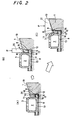
- This piston structure with a heat insulated combustion chamber comprises a piston body 1 formed of a piston head 4 and a piston skirt 5, and a combustion chamber structure 3 which is provided in a cavity 8 of the piston body 1 via heat insulating layers 11, 12, 13 so as to be positioned in the substantially central portion of the piston head 4, and which constitutes a sub-chamber, i.e. a combustion chamber 2.
- the piston body 1 is formed out of a metal material, such as an aluminum alloy, and the cavity 8 is formed in the central portion of the piston head 4.
- the combustion chamber structure 3 is formed out of a heat resisting material, such as a ceramic material including silicon nitride and sialon, and provided in its top wall 25 with a nozzle insert hole 7 positioned in the substantially central portion thereof, and a plurality of radially extending communication ports 9 arranged around the nozzle insert hole 7 so that the communication ports are spaced from one another.
- the combustion chamber structure 3 is provided on an outer circumferential surface of a bottom portion thereof with an outwardly extending flange 6 made integral therewith.
- the flange 6 has a function of fixing the combustion chamber structure 3 to the piston body 1.
- This piston structure with a heat insulated combustion chamber has a holding member 10 which is provided in the portion of the cavity 8 of the piston body 1 which is on the outer circumferential side of the combustion chamber structure 3 so as to press the flange 6 against a bottom surface of the cavity 8, and which is fixed to the piston body 1.
- the holding member 10 is formed concentrically with the combustion chamber structure 3 via a heat insulating layer 11 formed between the holding member 10 and an outer circumferential surface 14 of the combustion chamber structure 3.
- the contact portions 15 of the outer circumferential surface of the holding member 10 and wall surface of the cavity 8 of the piston body 1 are fixed to each other by hot-weld, such as laser welding, whereby the holding member 10 is fixed to the piston body 1.
- a piston top surface 19 of the piston body 1 and holding member 10 is tapered with recession in a central portion so that the angle thereof agrees with that of gas ejection outlets of the communication ports 9.
- the outer circumferential surface, which is opposed to the side surface of the cavity 8 is undercut.
- a heat insulating layer 13 is formed between the lower surface of the combustion chamber structure 3 and the bottom surface of the cavity 8 of the piston body 1.
- a heat insulating member 17 is provided on the bottom surface of the cavity of the piston body 1, and the combustion chamber structure 3 is placed on the heat insulating members 17.
- the heat insulating layers 11, 12, 13 can be formed of sealed heat insulating air layers, heat insulating members of a ceramic material may be packed in these heat insulating air layers.
- a heat insulating member 16 is interposed between the upper surface of the flange 6 and the holding member 10.
- the heat insulating member 17 is interposed between the lower surface of the flange 6 and the opposed surface of the piston body 1.
- the heat insulating members 16, 17 are formed out of, for example, a ceramic material including a partially stabilized zirconia PSZ.
- the heat insulating layer 13 is formed between the lower surface of the combustion chamber structure 3 and the piston body 1.
- a heat insulating gasket 18 is provided in a clearance between the outer circumferential surface 14 of the combustion chamber structure 3 and an inner circumferential surface 22 of the holding member 10.
- the heat insulating gasket 18 is locked by a stepped portion 24 formed on the inner circumferential surface of the holding member 10, in such a manner that the gasket 18 does not spring out from the clearance.
- the heat insulating gasket 18 is formed out of a material, such as SUS and SiC. Owing to the heat insulating gasket 18 interposed between the outer circumferential surface 14 of the combustion chamber structure 3 and the inner circumferential surface 22 of the holding member 10, the flowing of a gas can be minimized, and the degree of heat insulation can be improved.
- the combustion chamber structure 3 can be fixed to the inside of the cavity 8 of the piston body 1 as shown in Fig. 2.
- the combustion chamber structure 3 is provided in the cavity 8 formed in the piston body 1.
- the holding member 10 is then fixed at its contact portion 15 to the piston body 1 by beam welding and so on as shown in Fig. 2A.
- a clearance 26 occurs between the lower surface of the holding member 10 and the upper surface of the heat insulating member 16.
- the holding member 10 is then subjected to partial or all-around cold or hot pressing using a pressure member 20 as shown in Fig. 2B, whereby a region A shown by broken lines of the holding member 10 is deformed plastically in part or all-around to fill up the clearance 26, the holding member 10 being further pressed, whereby pre-stress is imparted thereto.
- the combustion chamber structure 3 is provided in the cavity 8 formed in the piston body 1.
- the holding member 10 is then fixed at its contact portion 15 to the piston body 1 by beam welding and so on as shown in Fig. 2A.
- a clearance 26 occurs between the lower surface of the holding member 10 and the upper surface of the heat insulating member 16.
- the holding member 10 is then subjected to partial cold or hot pressing using a pressure member 21, whereby a region B shown by a broken line in the top portions of the holding member 10 and piston body 1 is deformed plastically in part to fill up the clearance 26 in the deformed portions, the holding member 10 being further pressed, whereby residual stress is imparted thereto.
- the plastically deformed region B is formed so as to extend radially in a plurality of positions which are spaced from one another in the circumferential direction. Since the holding member 10 is pressed partially, the clearance 26 is closed partially, and clearances 26 are left sporadically in the other portions of the holding member 10, and these sporadically remaining clearances 26 also have a function of improving the heat insulating performance.
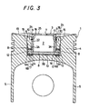
- a combustion chamber structure 3 in this embodiment comprises an upper structural member 3A constituting a circumferential side portion including a top wall 25, and a lower structural member 3B constituting a bottom portion.
- a flange 6 in the combustion chamber structure 3 is divided vertically into two, i.e., comprises upper and lower flange portions 6A, 6B.
- the upper flange portion 6A projects outward from an outer circumference of a lower portion of the upper structural member 3A.
- the lower flange portion 6B comprises a circumferential portion of the lower structural member 3B. Since the combustion chamber structure 3 is divided into two as mentioned above, it is manufactured easily.
- the upper and lower flange portions 6A, 6B are pressed against each other by the holding member 10, and the interfaces of these two flange portions are sealed excellently, so that a gas does not leak from the interfaces.
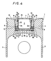
- a combustion chamber structure in this embodiment differs from that 3 shown in Fig. 3 in that a heat insulating gasket 23 is interposed between upper and lower flange portions 6A, 6B. Since the combustion chamber structure 3 in the embodiment of Fig. 4 is divided into two as mentioned above with the heat insulating gasket 23 interposed between the parts 6A and 6B, the irregularity of the interfaces of the two parts is offset by the heat insulating gasket 23, and the sealed condition of the structure can be improved.
Landscapes
- Engineering & Computer Science (AREA)
- Chemical & Material Sciences (AREA)
- Combustion & Propulsion (AREA)
- Mechanical Engineering (AREA)
- General Engineering & Computer Science (AREA)
- Ceramic Engineering (AREA)
- Combustion Methods Of Internal-Combustion Engines (AREA)
Claims (9)
- Kolbenstruktur mit einer wärmeisolierten Brennkammer, enthaltend einen Kolbenkörper (1), der mit einem Hohlraum (8) in einem oberen Abschnitt (25) davon versehen und aus einem Metallmaterial ausgebildet ist. Eine Brennkammerstruktur (3), die in diesem Hohlraum (8) angeordnet und aus einem wärmeresistenten Material ausgebildet ist. Einen Flansch (6), der einstückig mit der Brennkammerstruktur (3) ausgebildet ist und sich von einem äußeren Umfangsabschnitt einer Bodenwandung aus erstreckt, ein Halteelement (10), das fest in den Kolbenboden (1) eingepaßt und auf der äußeren Seite eine äußere Umfangsoberfläche (14) von dieser Brennkammerstruktur (3) sowie oberhalb dieses Flansches (6) positioniert ist, wobei dieses Haltelement (10) mittels Schweißen an dem Kolbenkörper (1) befestigt ist, diese Brennkammerstruktur (3) konzentrisch mit diesem Halteelement (10) angeordnet ist, dadurch gekennzeichnet, daß dieses Halteelement (10) fest eingepreßt ist, so daß dieser Flansch (6) von diesem Halteelement (10) gegen eine Bodenoberfläche dieses Hohlraums (8) von diesem Kolbenkörper (1) gepreßt wird, und das eine wärmeisolierende Schicht (11) zwischen diesem Halteelement (10) und einer äußeren Umfangsoberfläche (14) von dieser Brennkammerstruktur (3) ausgebildet wird, und daß dieses Halteelement (10) gegenüber diesem Flansch (6) vorgespannt ist, welcher Flansch (6) einstückig mit der Brennkammerstruktur (3) ausgebildet ist und zwar durch plastisches Deformieren eines Teiles des Kolbenkörpers (1) mit dem an den Kolbenkörper (1) befestigten Halteelement (10).
- Kolbenstruktur mit einer wärmeisolierten Brennkammer nach Anspruch 1, worin wärmeisolierende Schichten (12) sich von einer äußeren Umfangsoberfläche dieses Flansches (6) in Richtung auf eine obere Oberfläche von diesem Kolbenkörper (1) erstrecken und zwischen einem Abschnitt des Halteelements (10) ausgebildet ist, welches sich in der Nähe des Flansches (6) und dieses Hohlraums (8) von diesem Kolbenkörper (1) befindet.
- Kolbenstruktur mit einer wärmeisolierten Brennkammer nach Anspruch 1 oder Anspruch 2, worin wärmeisolierende Elemente (16, 17) zwischen einer oberen Oberfläche von diesem Flansch (6) und diesem Halteelement (10) und zwischen einer unteren Oberfläche von diesem Flansch (6) und von diesem Kolbenkörper (1) zwischengefügt sind.
- Kolbenstruktur mit einer wärmeisolierten Brennkammer nach einem der Ansprüche 1 bis 3, worin wärmeisolierende Schichten (13) zwischen einer unteren Oberfläche von dieser Brennkammerstruktur (3) und diesem Hohlraum (8) des Kolbenkörpers (10) ausgebildet sind.
- Kolbenstruktur mit einer wärmeisolierten Brennkammer nach einem der Ansprüche 1 bis 4, worin Dichtungen (8) zwischen einer äußeren Umfangsoberfläche (14) von dieser Brennkammerstruktur (3) und einer inneren Umfangsoberfläche (22) von diesem Haltelement (10) angeordnet sind.
- Kolbenstruktur mit einer wärmeisolierten Brennkammer nach einem der Ansprüche 1 bis 5, worin dieser Flansch (6) in dieser Brennkammerstruktur (3) zwei vertikal aufgeteilte Flanschabschnitte (6A, 6B) umfaßt.
- Kolbenstruktur mit einer wärmeisolierten Brennkammer nach Anspruch 6, worin wärmeisolierende Dichtungen (23) zwischen diesen Flanschabschnitten (6A, 6B) zwischengefügt sind.
- Kolbenstruktur mit einer wärmeisolierten Brennkammer nach einem der Ansprüche 1 bis 7, worin dieses Halteelement (10) derart plastisch deformiert ist, so daß eine Restdruckspannung in dem Halteelement (10) vorhanden ist.
- Kolbenstruktur mit einer wärmeisolierten Brennkammer nach einem der Ansprüche 1 bis 8, worin diese Brennkammerstruktur (3) mit einem Düseneinführungsloch (7) versehen ist, das in einem zentralen Bereich an dem oberen Abschnitt davon angeordnet ist, und worin Verbindungsöffnungen (9) um dieses Düseneinführungsloch (10) herum derart angeordnet sind, daß diese Verbindungsöffnungen (9) voneinander beabstandet sind und sich in radiale Richtung erstrecken.
Applications Claiming Priority (3)
| Application Number | Priority Date | Filing Date | Title |
|---|---|---|---|
| JP34857195A JP3409553B2 (ja) | 1995-12-20 | 1995-12-20 | 遮熱燃焼室付きピストンの構造 |
| JP34857195 | 1995-12-20 | ||
| JP348571/95 | 1995-12-20 |
Publications (2)
| Publication Number | Publication Date |
|---|---|
| EP0780554A1 EP0780554A1 (de) | 1997-06-25 |
| EP0780554B1 true EP0780554B1 (de) | 1999-07-28 |
Family
ID=18397919
Family Applications (1)
| Application Number | Title | Priority Date | Filing Date |
|---|---|---|---|
| EP96309295A Expired - Lifetime EP0780554B1 (de) | 1995-12-20 | 1996-12-19 | Kolbenaufbau mit wärmeisolierter Brennkammer |
Country Status (4)
| Country | Link |
|---|---|
| US (1) | US5738066A (de) |
| EP (1) | EP0780554B1 (de) |
| JP (1) | JP3409553B2 (de) |
| DE (1) | DE69603446T2 (de) |
Families Citing this family (3)
| Publication number | Priority date | Publication date | Assignee | Title |
|---|---|---|---|---|
| DE10113972C2 (de) * | 2001-03-22 | 2003-03-20 | Mtu Friedrichshafen Gmbh | Brennkraftmaschine und Verfahren zur Herstellung einer solchen |
| ES2323835B1 (es) * | 2007-06-29 | 2010-04-08 | Manuel Mariscal Muñoz | Piston ciclonico para motor de combustion interna dotado con movimiento alternativo. |
| FR2919341B1 (fr) * | 2007-07-27 | 2009-10-09 | Peugeot Citroen Automobiles Sa | Ensemble pour moteur a combustion interne et moteur a combustion interne equipe d'un tel ensemble |
Citations (1)
| Publication number | Priority date | Publication date | Assignee | Title |
|---|---|---|---|---|
| EP0775810A1 (de) * | 1995-11-23 | 1997-05-28 | Isuzu Motors Limited | Kolben mit Brennkammer |
Family Cites Families (14)
| Publication number | Priority date | Publication date | Assignee | Title |
|---|---|---|---|---|
| DE471839C (de) * | 1926-02-18 | 1929-02-16 | Acro A G | Selbstzuendende Einspritzbrennkraftmaschine, insbesondere fuer luftlose Einspritzung, mit einer im Kolben angeordneten, einen Teil des Verdichtungsraumes bildenden Kammer |
| DE525383C (de) * | 1928-06-28 | 1931-05-22 | Acro Akt Ges | Einspritzmotor mit dreigliedrigem Verdichtungsraum |
| GB408808A (en) * | 1932-09-23 | 1934-04-19 | Sebastian Nadal | Improvements in the combustion chambers of tnternal combustion engines of the liquid fuel injection type |
| JPS567226B2 (de) * | 1973-11-06 | 1981-02-17 | ||
| JPS5073704U (de) | 1973-11-12 | 1975-06-27 | ||
| GB1534761A (en) * | 1977-01-07 | 1978-12-06 | Advanced Materials Eng | Indirect injection diesel engines |
| GB1527791A (en) * | 1977-01-20 | 1978-10-11 | Wellworthy Ltd | Pistons |
| DE3714400A1 (de) * | 1986-05-07 | 1987-11-12 | Volkswagen Ag | Kolben fuer brennkraftmaschinen |
| JPS63176621A (ja) * | 1987-01-16 | 1988-07-20 | Ngk Insulators Ltd | 内燃機関の燃焼室構造 |
| JP3019529B2 (ja) * | 1990-10-19 | 2000-03-13 | いすゞ自動車株式会社 | 燃焼室を有するピストン |
| US5425337A (en) * | 1992-11-19 | 1995-06-20 | Izusu Ceramics Research Institute Co., Ltd. | Pre-chamber type engine |
| JP2814346B2 (ja) * | 1994-03-28 | 1998-10-22 | 株式会社いすゞセラミックス研究所 | ディーゼルエンジンの燃焼室構造 |
| JP3339198B2 (ja) * | 1994-08-26 | 2002-10-28 | いすゞ自動車株式会社 | 燃焼室を持つピストンの構造 |
| US5520148A (en) * | 1995-03-13 | 1996-05-28 | Isuzu Motors Limited | Heat insulating structure for swirl chambers |
-
1995
- 1995-12-20 JP JP34857195A patent/JP3409553B2/ja not_active Expired - Fee Related
-
1996
- 1996-12-13 US US08/766,669 patent/US5738066A/en not_active Expired - Lifetime
- 1996-12-19 DE DE69603446T patent/DE69603446T2/de not_active Expired - Fee Related
- 1996-12-19 EP EP96309295A patent/EP0780554B1/de not_active Expired - Lifetime
Patent Citations (1)
| Publication number | Priority date | Publication date | Assignee | Title |
|---|---|---|---|---|
| EP0775810A1 (de) * | 1995-11-23 | 1997-05-28 | Isuzu Motors Limited | Kolben mit Brennkammer |
Also Published As
| Publication number | Publication date |
|---|---|
| DE69603446D1 (de) | 1999-09-02 |
| US5738066A (en) | 1998-04-14 |
| DE69603446T2 (de) | 2000-03-23 |
| EP0780554A1 (de) | 1997-06-25 |
| JPH09170437A (ja) | 1997-06-30 |
| JP3409553B2 (ja) | 2003-05-26 |
Similar Documents
| Publication | Publication Date | Title |
|---|---|---|
| JP2718071B2 (ja) | 副室式断熱エンジン | |
| US9951712B2 (en) | Internal combustion engine with interbore cooling | |
| US5097807A (en) | Combustion chamber for diesel engines | |
| US5645028A (en) | Piston structure with a combustion chamber | |
| JPH0357817A (ja) | 副室の断熱構造 | |
| US4304199A (en) | Cylinder head for compression-ignition internal combustion engines having precombustion chambers | |
| JPH0212265Y2 (de) | ||
| JPS61142320A (ja) | デイ−ゼル機関の燃焼室 | |
| US4513703A (en) | Reciprocating piston internal combustion engine | |
| EP0780554B1 (de) | Kolbenaufbau mit wärmeisolierter Brennkammer | |
| EP0430419B1 (de) | Wärmeisolierte Brennkraftmaschine mit Wirbelkammer | |
| JPS61123714A (ja) | 内燃機関の副室構造 | |
| JPS608449A (ja) | エンジンの耐熱応力構造 | |
| US5014664A (en) | Heat-insulating structure of swirl chamber | |
| EP0775810B1 (de) | Kolben mit Brennkammer | |
| JP3170007B2 (ja) | 火花点火式エンジンのスキッシュ構造 | |
| JPH0134661Y2 (de) | ||
| JPH029066Y2 (de) | ||
| JPH0115861Y2 (de) | ||
| GB2049806A (en) | Cylinder Head for Compression- ignition Internal Combustion Engines having Precombustion Chambers | |
| JPH0754580Y2 (ja) | エンジンの副室構造 | |
| JPH0134660Y2 (de) | ||
| JPS6350424Y2 (de) | ||
| JPH0238027Y2 (de) | ||
| JP2582743Y2 (ja) | 分割副室用リングを有する副室式エンジン |
Legal Events
| Date | Code | Title | Description |
|---|---|---|---|
| PUAI | Public reference made under article 153(3) epc to a published international application that has entered the european phase |
Free format text: ORIGINAL CODE: 0009012 |
|
| AK | Designated contracting states |
Kind code of ref document: A1 Designated state(s): DE FR GB IT |
|
| 17P | Request for examination filed |
Effective date: 19970909 |
|
| 17Q | First examination report despatched |
Effective date: 19971017 |
|
| GRAG | Despatch of communication of intention to grant |
Free format text: ORIGINAL CODE: EPIDOS AGRA |
|
| GRAG | Despatch of communication of intention to grant |
Free format text: ORIGINAL CODE: EPIDOS AGRA |
|
| GRAH | Despatch of communication of intention to grant a patent |
Free format text: ORIGINAL CODE: EPIDOS IGRA |
|
| GRAH | Despatch of communication of intention to grant a patent |
Free format text: ORIGINAL CODE: EPIDOS IGRA |
|
| GRAA | (expected) grant |
Free format text: ORIGINAL CODE: 0009210 |
|
| AK | Designated contracting states |
Kind code of ref document: B1 Designated state(s): DE FR GB IT |
|
| ET | Fr: translation filed | ||
| REF | Corresponds to: |
Ref document number: 69603446 Country of ref document: DE Date of ref document: 19990902 |
|
| PLBE | No opposition filed within time limit |
Free format text: ORIGINAL CODE: 0009261 |
|
| STAA | Information on the status of an ep patent application or granted ep patent |
Free format text: STATUS: NO OPPOSITION FILED WITHIN TIME LIMIT |
|
| 26N | No opposition filed | ||
| PGFP | Annual fee paid to national office [announced via postgrant information from national office to epo] |
Ref country code: FR Payment date: 20001113 Year of fee payment: 5 |
|
| PGFP | Annual fee paid to national office [announced via postgrant information from national office to epo] |
Ref country code: GB Payment date: 20001120 Year of fee payment: 5 |
|
| PGFP | Annual fee paid to national office [announced via postgrant information from national office to epo] |
Ref country code: DE Payment date: 20001122 Year of fee payment: 5 |
|
| PG25 | Lapsed in a contracting state [announced via postgrant information from national office to epo] |
Ref country code: GB Free format text: LAPSE BECAUSE OF NON-PAYMENT OF DUE FEES Effective date: 20011219 |
|
| REG | Reference to a national code |
Ref country code: GB Ref legal event code: IF02 |
|
| PG25 | Lapsed in a contracting state [announced via postgrant information from national office to epo] |
Ref country code: DE Free format text: LAPSE BECAUSE OF NON-PAYMENT OF DUE FEES Effective date: 20020702 |
|
| GBPC | Gb: european patent ceased through non-payment of renewal fee |
Effective date: 20011219 |
|
| PG25 | Lapsed in a contracting state [announced via postgrant information from national office to epo] |
Ref country code: FR Free format text: LAPSE BECAUSE OF NON-PAYMENT OF DUE FEES Effective date: 20020830 |
|
| REG | Reference to a national code |
Ref country code: FR Ref legal event code: ST |
|
| PG25 | Lapsed in a contracting state [announced via postgrant information from national office to epo] |
Ref country code: IT Free format text: LAPSE BECAUSE OF NON-PAYMENT OF DUE FEES;WARNING: LAPSES OF ITALIAN PATENTS WITH EFFECTIVE DATE BEFORE 2007 MAY HAVE OCCURRED AT ANY TIME BEFORE 2007. THE CORRECT EFFECTIVE DATE MAY BE DIFFERENT FROM THE ONE RECORDED. Effective date: 20051219 |