EP0779637A2 - Circuit breaker with closing resistor - Google Patents
Circuit breaker with closing resistor Download PDFInfo
- Publication number
- EP0779637A2 EP0779637A2 EP96810782A EP96810782A EP0779637A2 EP 0779637 A2 EP0779637 A2 EP 0779637A2 EP 96810782 A EP96810782 A EP 96810782A EP 96810782 A EP96810782 A EP 96810782A EP 0779637 A2 EP0779637 A2 EP 0779637A2
- Authority
- EP
- European Patent Office
- Prior art keywords
- contact
- resistance
- circuit breaker
- power interruption
- interruption point
- Prior art date
- Legal status (The legal status is an assumption and is not a legal conclusion. Google has not performed a legal analysis and makes no representation as to the accuracy of the status listed.)
- Withdrawn
Links
Images

Classifications
-
- H—ELECTRICITY
- H01—ELECTRIC ELEMENTS
- H01H—ELECTRIC SWITCHES; RELAYS; SELECTORS; EMERGENCY PROTECTIVE DEVICES
- H01H33/00—High-tension or heavy-current switches with arc-extinguishing or arc-preventing means
- H01H33/02—Details
- H01H33/04—Means for extinguishing or preventing arc between current-carrying parts
- H01H33/16—Impedances connected with contacts
- H01H33/166—Impedances connected with contacts the impedance being inserted only while closing the switch
-
- H—ELECTRICITY
- H01—ELECTRIC ELEMENTS
- H01H—ELECTRIC SWITCHES; RELAYS; SELECTORS; EMERGENCY PROTECTIVE DEVICES
- H01H33/00—High-tension or heavy-current switches with arc-extinguishing or arc-preventing means
- H01H33/02—Details
- H01H2033/028—Details the cooperating contacts being both actuated simultaneously in opposite directions
Definitions
- the invention is based on a circuit breaker according to the preamble of claim 1.
- Patent specification EP 0 152 583 B1 describes a circuit breaker with an on-resistance which can be used in a high-voltage network.
- This circuit breaker has two quenching chambers connected in series and an on-resistance which is made up of two partial resistors.
- This switch-on resistance is bridged after switching on by means of a resistance contact.
- the switch-on resistor is located in the middle between the two quenching chambers.
- the resistance contact closes after the extinguishing chambers when switched on and opens after the extinguishing chambers when switched off.
- the resistance contact is actuated by a comparatively complex drive mechanism.
- the invention has for its object to provide a circuit breaker with an on-resistance and a resistance contact, which is simple and space-saving, and in which the precise actuation of the resistance contact is achieved with simple means.
- the circuit breaker according to the invention can be used in any installation position without modifications. It is particularly suitable for outdoor switches, but it is very easy to install the arcing chamber of this circuit breaker with an on-resistance, even in metal-encapsulated gas-insulated switchgear.
- a circuit breaker has a cylindrical quenching chamber 2, which extends along a central axis 1, of which, however, only an insulating housing 3, which closes off the quenching chamber volume to the outside, including a metallic connecting flange 3a and a metal housing 4 partially guiding the exhaust gases is shown.
- the quenching chamber volume is filled with an insulating gas, usually SF 6 gas.
- the arcing chamber 2 has a pair of erosion contacts. The erosion contacts of the extinguishing chamber 2 are both moved here, namely by a drive (not shown) in connection with two racks arranged diametrically opposite one another, as is described, for example, in the patent specification EP 0 313 813 B1.
- each racks are each mechanically coupled to an actuating rod 5, 6 made of steel.
- the actuating rods 5 and 6 extend along the axes 7 and 8, the axes 7 and 8 likewise being diametrically opposed to one another and running parallel at the same distance from the central axis 1.
- each of the actuating rods 5 and 6 is provided with a coupling element 9, 10 of the same design, the construction of which will be described later. Only a part of the coupling element 10 can be seen in FIG. 1, and the coupling elements 9 and 10 are shown completely in FIGS. 2 and 3.
- the metal housing 4 has an end flange 11 which has two bores each with a plastic guide part 12.
- the actuating rods 5 and 6 are guided in the plastic guide parts 12.
- the end flange 11 is electrically conductively connected to a metallic carrier 13.
- the housing 3 is pressure-tightly connected to an intermediate flange 14 made of metal.
- the intermediate flange 14 is provided as a power connection on this side of the arcing chamber 2.
- a disc 15 made of insulating material is let into the intermediate flange 14.
- the disc 15 has through openings 16 which allow the SF 6 gas to flow through.
- the disc 15, which is connected to the intermediate flange 14 on the one hand, is rigidly connected to the metallic carrier 13 by means of a flange-shaped retaining ring 17.
- the retaining ring 17 also serves to fasten two elastic buffers 18.
- the actuating rods 5 and 6 penetrate the end flange 11, a shoulder of the carrier 13 and the buffers 18.
- a collar 19 is worked on the carrier 13 on the side facing away from the end flange 11, the latter the shoulder facing the end flange 11 supports an annular elastic stop 20.
- the carrier 13 On the side facing away from the end flange 11, the carrier 13 is connected to a cylindrical piston 21, in which spiral contacts 22 and plastic guide rings associated therewith are partially embedded on its outer surface.
- a metallic contact cylinder 23 slides on the spiral contacts 22 and the guide rings.
- the contact cylinder 23 has a radially outwardly directed bead 24 on the side facing away from the end flange 11.
- the bead 24 can consist, for example, of silver-plated tungsten copper.
- the contact cylinder 23 On the side facing the end flange 11, the contact cylinder 23 is provided with a cylinder base 25, into which the actuating rods 5 and 6 are screwed.
- the intermediate flange 14 is pressure-tight and electrically conductive with a metallic housing 28 which concentrically surrounds the contact cylinder 23.
- a flange 29 is attached, to which a closed metallic resistance housing 30 is flanged in a pressure-tight and electrically conductive manner.
- a contact carrier 31 is flanged to the flange 29 and holds a cylindrical, basket-like arrangement of spring-mounted contact fingers 32.
- the contact carrier 31 has through openings, not shown, which connect the volume within the housing 28 to the volume enclosed by the resistance housing 30, so that the SF 6 gas can be exchanged here.
- the contact fingers 32 form with the contact cylinder 23 a detachable contact arrangement, which is referred to as a resistance contact 33.
- a resistance contact 33 When the resistance contact 33 is switched on, the contact fingers 32 engage the bead 24 of the contact cylinder 23 and hold the contact cylinder 23 in its switched-on position with their spring force.
- the resistance contact 33 is designed such that it can carry the full rated current of the circuit breaker for an unlimited time.
- an insulation body 34 is fastened, which has a central opening 35.
- the insulation body 34 carries a contact plate 36 made of metal, which has a central bore 37.
- a Spiral contact 38 inserted, which makes electrical contact with the surface of a piston rod 39 which is integrally formed on the piston 21 and extends it in the axial direction.
- the piston rod 39 penetrates the contact carrier 31, the insulation body 34 and the contact plate 36.
- the piston rod 39 is extended after the contact plate 36 in the axial direction by a central guide pin 40 which is surrounded by an insulating tube 41.
- the resistance bodies 42 are coated on the outside in such a way that decomposition products of the SF 6 gas cannot attack their surface.
- a cylindrically shaped metallic pressure disc 43 with a central bore which is somewhat larger in diameter than the diameter of the insulating tube 41 is pushed on.
- a stack of disc springs 44 is pushed onto the insulating tube 41, which is also guided through the insulating tube 41 and which is supported against the metallic resistance housing 30.
- the coupling element 9 has a cylindrical housing 45 made of an aluminum alloy, which is closed by a corresponding cover 46 on its left side, which faces the erosion contacts of the arcing chamber 2.
- the actuating rod 5, which is directly connected to the upper rack of the arcing chamber 2 is screwed into the center of the cover 46 and secured by means of a lock nut 47.
- the housing 45 has a central bore 48 which has a somewhat larger diameter on the side facing the cover 46. In the area of the larger diameter, a disk spring assembly 49 is installed, which is supported against the cover 46 and a collar 50 opposite the cover 46 in the central bore 48.
- the central bore 48 is at least partially lined with a sliding sleeve 51, which is usually made of a steel alloy.
- the sliding sleeve 51 is somewhat shorter than the area of the smaller diameter of the central bore 48, a second plate spring assembly 53 being positioned in the central bore 48 between the end of the sliding sleeve 51 facing away from the cover 46 and the end part 52 of the housing 45.
- the actuating rod 5 is provided on the end facing the cover 46 with a piston 55, which has at least one piston ring 56, which is made of polytetrafluoroethylene, for example, and which is displaceable in the sliding sleeve 51.
- the piston 55 travels a stroke H1 from the off position to the on position.
- FIG. 3 shows the coupling element 10 extending along the axis 8 with the extinguishing chamber 2 switched on.
- the coupling element 10 is constructed exactly the same as the coupling element 9.
- the actuating rod 6 is screwed into the cover 46 on the side facing the erosion contacts of the extinguishing chamber 2.
- the extension of the actuating rod 6, which emerges to the right from the housing 45, is formed on the piston 57 moving in the sliding sleeve 51.
- the piston 57 In the switched-on position of the quenching chamber 2, the piston 57, as shown in FIG.
- the coupling element 9 interrupts the actuating rod 5 in such a way that the axis 7, along which the actuating rod 5 moves, is retained for both parts of the actuating rod 5.
- the coupling element 10 interrupts the actuating rod 6 in such a way that the axis 8 along which the actuating rod 6 moves is retained for both parts of the actuating rod 6.
- the movement of the contact cylinder 23 of the resistance contact 33 is delayed because of the rack Axial movement transmitted to the housing 45 via the actuating rod 6 and the cover 46 to the left only after the housing 45 has covered the stroke H2 is transmitted to the piston 55 and thus via the right continuation of the actuating rod 5 to the contact cylinder 23.
- the movement of the contact cylinder 23 therefore begins only after the disk spring assembly 53 has hit the shoulder 58 of the piston 55.
- the two coupling elements 9 and 10 the different effects of which are described here when switching on and off, always work in parallel with one another, thereby reliably preventing the moving parts from tilting.
- the quenching chamber drive can therefore advantageously be designed for a comparatively small drive energy, since comparatively little energy has to be expended additionally for the movement of the coupled resistance contact 33.
- the circuit breaker has an input terminal 59 and an output terminal 60, between which the mains voltage present lies.
- the circuit breaker also has a power interruption point 61 and a rated current interruption point 62 in parallel with it.
- the input terminal 59 is connected to a terminal 63 via the rated current interruption point 62 and to a terminal 64 via the power interruption point 61.
- the two terminals 63 and 64 are also connected to one another in an electrically conductive manner.
- the terminal 63 is connected to the outgoing terminal 60 via a switch-on resistor 65.
- the terminal 64 is over the Resistor contact 33 connected to outgoing terminal 60.
- the switch-on resistor 65 is made up of a large number of resistance bodies 42.
- the end flange 11 is at the potential of the terminals 63 and 64.
- the connection from the terminal 63 to the outgoing terminal 60 is through the carrier 13, the piston 21, the piston rod 39, the spiral contacts 38, the contact plate 36, the resistor body 42, the Thrust washer 43, the plate springs 44, the resistance housing 30, the housing 28 and the intermediate flange 14 embodied.
- the connection from the terminal 64 via the closed resistance contact 33 to the outgoing terminal 60 is embodied by the carrier 13, the piston 21, the spiral contacts 22, the contact cylinder 23, the contact fingers 32, the contact carrier 31, the housing 28 and the intermediate flange 14.
- FIG. 4 is first considered in more detail.
- the power interruption point 61 When switching on, the power interruption point 61 first switches on the circuit, specifically the current flows from the input terminal 59 via the power interruption point 61 and the switch-on resistor 65 connected in series to the output terminal 60.
- the rated current interruption point 62 then closes somewhat later.
- this current is limited by the switch-on resistor 65, undesirably high switch-on overvoltages caused by the switch-on process cannot form in the network.
- the switch-on resistor 65 must not remain in the circuit for too long, since it would otherwise be thermally overloaded.
- the resistance contact 33 therefore short-circuits the switch-on resistor 65 after a predetermined time delay, ie it bridges the switch-on resistor 65 so that it is thermally relieved. This time delay required when switching on is generated by the coupling elements 9 and 10.
- the rated current interruption point 62 opens first and the current commutates onto the current path through the power interruption point 61, only then does the power interruption point 61 open and the arc burning therein is then extinguished, with the result that the circuit is interrupted. Only then, also with a time delay, does the resistance contact 33 open and the switch-off process is completed. This time delay required when switching off is likewise generated by the coupling elements 9 and 10, wherein different time delays can be set by changing the stroke H2.
- the actuating rods 5 and 6 which are directly connected to the toothed racks are moved to the right together with the housings 45 connected to them.
- the arcing chamber 2 closes, ie the nominal current interruption point 62 and the power interruption point 61, so that the on-resistance 65 lies in the circuit.
- the current now flows from the end flange 11 through the carrier 13, the piston 21, the piston rod 39, the spiral contacts 38, the contact plate 36, the resistance body 42, the thrust washer 43, the plate springs 44, the resistance housing 30, the housing 28 and through the intermediate flange 14 out of the circuit breaker.
- the contact fingers 32 are designed such that they slide over the bead 24 of the contact cylinder 23 and then hold the contact cylinder 23 in position in a form-fitting manner.
- the latter In the final switch-on position of the contact cylinder 23, the latter is braked by the elastic stop 20, on which the cylinder base 25 strikes.
- the coil spring 27 is biased.
- the current flows from the end flange 11 through the carrier 13, the piston 21, the spiral contacts 22, the contact cylinder 23, the contact fingers 32, the contact carrier 31, the housing 28 and the intermediate flange 14 out of the circuit breaker. In this position of the circuit breaker, only insignificant stray currents flow through the resistor body 42 and do not thermally load the resistor.
- the pistons 55 and 57 are in the position shown in FIG.
- the actuating rods 5 and 6 directly connected to the toothed racks are moved to the left together with the housings 45 connected to them.
- the quenching chamber 2 opens, ie the nominal current interruption point 62 and the power interruption point 61 open.
- the contact cylinder 23 remains in its switch-on position, held by the contact fingers 32.
- the force of the prestressed spiral spring 27 alone is not sufficient to release the positive connection between the contact fingers 32 and the contact cylinder 23. Even in the case of a vertical construction, if the dead weight of the contact cylinder 23, in addition to the other forces, is to be held by the contact fingers 32, this form-fitting connection does not come off by itself.
- the contact cylinder 23 is moved further to the left in the direction of the end flange 11 by the force of the prestressed coil spring 27 until the cylinder base 25 or the two lock nuts 26 hit the two elastic buffers 18.
- the buffers 18 limit the stroke of the contact cylinder 23 in its switch-off position.
- the pistons 55 and 57 are then in the position shown in FIG. 2, the switch-off process is complete and the coupling elements 9 and 10 are again ready for the next switch-on.
- the exemplary embodiment described in detail here shows an arcing chamber 2 with two erosion contacts which move in opposite directions.
- the electrical equivalent circuit diagram shown in FIG. 4 also being valid here.
- the actuating rods 5 and 6 may have to be made at least partially of an insulating material, this is particularly the case when the end flange 11 is connected to the fixed erosion contact, so that the entire extinguishing path of the arcing chamber 2 through the actuating rods 5 and 6 must be spanned.
- the actuating rods 5 and 6 must be made of a temperature-resistant insulating material at least in the area of the extinguishing section.
Abstract
Der Leistungsschalter ist mit mindestens einer entlang einer zentralen Achse (1) erstreckten Löschkammer (2) versehen, welche mindestens eine Leistungsunterbrechungsstelle (61) mit mindestens einem durch einen Antrieb bewegten Kontakt aufweist. Zur Leistungsunterbrechungsstelle (61) ist ein Einschaltwiderstand (65) in Reihe geschaltet, mit einem Widerstandskontakt (33), welcher parallel zum Einschaltwiderstand (65) geschaltet ist, und welcher beim Einschaltvorgang nach der Leistungsunterbrechungsstelle (61) schliesst und beim Ausschaltvorgang nach der Leistungsunterbrechungsstelle (61) öffnet. Es soll ein Leistungsschalter mit einem Einschaltwiderstand und einem Widerstandskontakt angegeben werden, der einfach und platzsparend aufgebaut ist, und bei dem die zeitgenaue Betätigung des Widerstandskontakts mit einfachen Mitteln erreicht wird. Dies wird dadurch erreicht, dass der Widerstandskontakt (33) geradlinig entlang mindestens einer Achse (7,8) mechanisch mit dem mindestens einen bewegten Kontakt verbunden ist, dass in die geradlinige mechanische Verbindung jeweils ein Koppelelement (9,10) zwischengeschaltet ist, und dass das Koppelelement (9,10) so ausgelegt ist, dass es sowohl beim Einschaltvorgang als auch beim Ausschaltvorgang zeitlich verzögernd wirkt. <IMAGE>The circuit breaker is provided with at least one quenching chamber (2) which extends along a central axis (1) and which has at least one power interruption point (61) with at least one contact moved by a drive. An on-resistance (65) is connected in series to the power interruption point (61), with a resistance contact (33) which is connected in parallel with the on-resistance (65) and which closes after the power interruption point (61) during the switch-on process and after the power interruption point during the switch-off process ( 61) opens. A circuit breaker with a closing resistor and a resistance contact is to be specified, which is simple and space-saving, and in which the precise actuation of the resistance contact is achieved with simple means. This is achieved in that the resistance contact (33) is mechanically connected in a straight line along at least one axis (7, 8) to the at least one moving contact, in that a coupling element (9, 10) is interposed in each case in the straight mechanical connection, and in that the coupling element (9, 10) is designed in such a way that it acts with a time delay both when switching on and when switching off. <IMAGE>
Description
Bei der Erfindung wird ausgegangen von einem Leistungsschalter gemäss dem Oberbegriff des Anspruchs 1.The invention is based on a circuit breaker according to the preamble of
In der Patentschrift EP 0 152 583 B1 ist ein Leistungsschalter mit einem Einschaltwiderstand beschrieben, der in einem Hochspannungsnetz eingesetzt werden kann. Dieser Leistungsschalter weist zwei in Reihe geschaltete Löschkammern auf und einen Einschaltwiderstand, der aus zwei Teilwiderständen aufgebaut ist. Dieser Einschaltwiderstand wird nach dem Einschalten mittels eines Widerstandskontakts überbrückt. Der Einschaltwiderstand ist in der Mitte zwischen den beiden Löschkammern angeordnet. Der Widerstandskontakt schliesst beim Einschalten nach den Löschkammern und öffnet sich beim Ausschalten nach den Löschkammern. Der Widerstandskontakt wird durch einen vergleichsweise aufwendigen Antriebsmechanismus betätigt.Patent specification EP 0 152 583 B1 describes a circuit breaker with an on-resistance which can be used in a high-voltage network. This circuit breaker has two quenching chambers connected in series and an on-resistance which is made up of two partial resistors. This switch-on resistance is bridged after switching on by means of a resistance contact. The switch-on resistor is located in the middle between the two quenching chambers. The resistance contact closes after the extinguishing chambers when switched on and opens after the extinguishing chambers when switched off. The resistance contact is actuated by a comparatively complex drive mechanism.
Aus der US-Patentschrift 4,421,962 ist ein weiterer Leistungsschalter mit einem Einschaltwiderstand bekannt. Bei diesem Leistungsschalter wird der Einschaltwiderstand beim Einschalten mittels eines Hilfskontakts in den Stromkreis geschaltet und danach dann durch die sich schliessenden Löschkammerkontakte überbrückt.Another circuit breaker with an on-resistance is known from US Pat. No. 4,421,962. With this circuit breaker, the closing resistance is switched into the circuit by means of an auxiliary contact when it is switched on and then bridged by the closing arcing chamber contacts.
Der Erfindung, wie sie im Patentanspruch 1 definiert ist, liegt die Aufgabe zugrunde, einen Leistungsschalter mit einem Einschaltwiderstand und einem Widerstandskontakt anzugeben, der einfach und platzsparend aufgebaut ist, und bei dem die zeitgenaue Betätigung des Widerstandskontakts mit einfachen Mitteln erreicht wird.The invention, as defined in
Der erfindungsgemässe Leistungsschalter kann ohne Modifikationen in jeder Einbaulage eingesetzt werden. Er ist besonders für Freiluftschalter geeignet, ein Einbau der mit einem Einschaltwiderstand bestückten Löschkammer dieses Leistungsschalters ist jedoch sehr einfach auch in metallgekapselten gasisolierten Schaltanlagen möglich.The circuit breaker according to the invention can be used in any installation position without modifications. It is particularly suitable for outdoor switches, but it is very easy to install the arcing chamber of this circuit breaker with an on-resistance, even in metal-encapsulated gas-insulated switchgear.
Das Einschaltverhalten bereits im Betrieb stehender Leistungsschalter kann durch die Nachrüstung dieser Leistungsschalter mit einem Einschaltwiderstand samt zugehörigem Widerstandskontakt entscheidend verbessert werden. Eine derartige Nachrüstung ist mit vergleichsweise geringem Aufwand möglich, da nur eine geringe Anzahl von Teilen hierfür benötigt wird. Zudem ist es sehr vorteilhaft, dass der Platzbedarf für diese Aufwertung des Leistungsschalters sehr gering ist, sodass diese Aufwertung keine aufwendigen Umbauten in der bereits bestehenden Schaltanlage erfordert.The switch-on behavior of circuit breakers that are already in operation can be decisively improved by retrofitting these circuit breakers with a switch-on resistor including the associated resistance contact. Retrofitting of this type is possible with comparatively little effort, since only a small number of parts are required for this. It is also very advantageous that the space required for this upgrade of the circuit breaker is very small, so that this upgrade no expensive conversions in the existing switchgear required.
Ein Ausführungsbeispiel der Erfindung und die damit erzielbaren Vorteile wird nachfolgend anhand der Zeichnung, welche lediglich einen möglichen Ausführungsweg darstellt, näher erläutert.An exemplary embodiment of the invention and the advantages which can be achieved thereby are explained in more detail below with reference to the drawing, which only represents one possible embodiment.
Es zeigen:
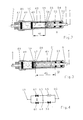
- Fig.1 einen ersten Teilschnitt durch einen erfindungsgemässen Leistungsschalter, wobei die obere Zeichnungshälfte den ausgeschalteten und die untere Zeichnungshälfte den eingeschalteten Zustand darstellt,
- Fig.2 zeigt einen Schnitt durch ein erstes Koppelelement des Leistungsschalters im ausgeschalteten Zustand,
- Fig.3 zeigt einen Schnitt durch ein zweites Koppelelement des Leistungsschalters im eingeschalteten Zustand, und
- Fig.4 zeigt ein schematisches elektrisches Ersatzschaltbild eines mit einer Löschkammer ausgeführten Leistungsschalters.
- 1 shows a first partial section through a circuit breaker according to the invention, the upper half of the drawing showing the switched off and the lower half of the drawing showing the switched on state,
- 2 shows a section through a first coupling element of the circuit breaker in the switched-off state,
- 3 shows a section through a second coupling element of the circuit breaker in the switched-on state, and
- 4 shows a schematic electrical equivalent circuit diagram of a circuit breaker designed with an arcing chamber.
Bei allen Figuren sind gleich wirkende Elemente mit gleichen Bezugszeichen versehen. Alle für das unmittelbare Verständnis der Erfindung nicht erforderlichen Elemente sind nicht dargestellt.Elements with the same effect are provided with the same reference symbols in all the figures. All elements not necessary for the immediate understanding of the invention are not shown.
Ein Leistungsschalter weist eine zylindrisch ausgebildete, längs einer zentralen Achse 1 erstreckte Löschkammer 2 auf, von der jedoch lediglich ein das Löschkammervolumen nach aussen abschliessendes isolierendes Gehäuse 3 samt metallischem Anschlussflansch 3a und ein zum Teil die Auspuffgase führendes Metallgehäuse 4 dargestellt ist. Das Löschkammervolumen ist mit einem isolierenden Gas, in der Regel SF6-Gas, gefüllt. Die Löschkammer 2 weist ein Paar Abbrandkontakte auf. Die Abbrandkontakte der Löschkammer 2 werden hier beide bewegt, und zwar durch einen nicht dargestellten Antrieb in Verbindung mit zwei einander diametral gegenüberstehend angeordneten Zahnstangen, wie dies beispielsweise in der Patentschrift EP 0 313 813 B1 beschrieben ist. Beim erfindungsgemässen Leistungsschalter sind diese Zahnstangen jeweils mit einer aus Stahl gefertigten Betätigungsstange 5,6 mechanisch gekoppelt. Die Betätigungsstangen 5 und 6 erstrecken sich entlang der Achsen 7 und 8, wobei die Achsen 7 und 8 ebenfalls einander diametral gegenüberstehen und parallel im gleichen Abstand zur zentralen Achse 1 verlaufen. Im Bereich des Metallgehäuses 4 ist jede der Betätigungsstangen 5 und 6 mit einem gleich ausgebildeten Koppelelement 9,10 versehen, dessen Aufbau später beschrieben wird. In der Fig.1 ist lediglich ein Teil des Koppelelementes 10 zu sehen, in den Fig.2 und 3 sind die Koppelelemente 9 und 10 vollständig dargestellt. Das Metallgehäuse 4 weist einen Endflansch 11 auf, der mit zwei mit jeweils einem Kunststoffführungsteil 12 ausgestattete Bohrungen aufweist. In den Kunststoffführungsteilen 12 werden die Betätigungsstangen 5 und 6 geführt. Der Endflansch 11 ist elektrisch leitend mit einem metallischen Träger 13 verbunden.A circuit breaker has a
Das Gehäuse 3 ist druckdicht mit einem Zwischenflansch 14 aus Metall verbunden. Der Zwischenflansch 14 ist als Stromanschluss auf dieser Seite der Löschkammer 2 vorgesehen. In den Zwischenflansch 14 ist eine Scheibe 15 aus Isoliermaterial eingelassen. Die Scheibe 15 weist durchgehende Öffnungen 16 auf, die ein Durchströmen des SF6-Gases erlauben. Die einerseits mit dem Zwischenflansch 14 verbundene Scheibe 15 ist andererseits mittels eines flanschartig ausgebildeten Halterings 17 starr mit dem metallischen Träger 13 verbunden. Der Haltering 17 dient zudem der Befestigung von zwei elastischen Puffern 18. Die Betätigungsstangen 5 und 6 durchdringen den Endflansch 11, einen Absatz des Trägers 13 und die Puffer 18. Am Träger 13 ist auf der dem Endflansch 11 abgewandten Seite ein Bund 19 angearbeitet, dessen dem Endflansch 11 zugewandte Schulter einen ringförmig ausgebildeten elastischen Anschlag 20 abstützt. Auf der dem Endflansch 11 abgewandten Seite ist der Träger 13 mit einem zylindrisch ausgebildeten Kolben 21 verbunden, in den auf seiner äusseren Fläche Spiralkontakte 22 und diesen zugeordnete Führungsringe aus Kunststoff teilweise eingelassen sind. Auf den Spiralkontakten 22 und den Führungsringen gleitet ein metallischer Kontaktzylinder 23. Der Kontaktzylinder 23 weist auf der dem Endflansch 11 abgewandten Seite eine radial nach aussen gerichtete Wulst 24 auf. Die Wulst 24 kann beispielsweise aus versilbertem Wolframkupfer bestehen. Auf der dem Endflansch 11 zugewandten Seite ist der Kontaktzylinder 23 mit einem Zylinderboden 25 versehen, in welchen die Betätigungsstangen 5 und 6 eingeschraubt sind. Diese Schraubverbindungen sind mit jeweils einer Kontermutter 26 gesichert. Diese Kontermuttern 26 wirken beim Ausschalten mit den Puffern 18 zusammen, während beim Einschalten der Zylinderboden 25 auf den Anschlag 20 auftrifft. Im Raum zwischen dem Kontaktzylinder 23 und dem Träger 13 ist eine Spiralfeder 27 vorgesehen, welche den Kontaktzylinder 23 mit einer Kraft in Richtung auf den Endflansch 11 zu beaufschlagt.The
Der Zwischenflansch 14 ist druckdicht und elektrisch leitend mit einem metallischen Gehäuse 28 verbunden, welches den Kontaktzylinder 23 konzentrisch umgibt. Auf der dem Zwischenflansch 14 abgewandten Seite des Gehäuses 28 ist ein Flansch 29 angebracht an den ein geschlossenes metallisches Widerstandsgehäuse 30 druckdicht und elektrisch leitend angeflanscht ist. Im Innern des Gehäuses 28 ist an den Flansch 29 ein Kontaktträger 31 angeflanscht, der eine zylindrisch ausgebildete, korbartige Anordnung von federnd befestigten Kontaktfingern 32 hält. Der Kontaktträger 31 weist nicht dargestellte Durchgangsöffnungen auf, die das Volumen innerhalb des Gehäuses 28 mit dem vom Widerstandsgehäuse 30 umschlossenen Volumen verbinden, sodass hier ein Austausch des SF6-Gases stattfinden kann. Die Kontaktfinger 32 bilden mit dem Kontaktzylinder 23 eine lösbare Kontaktanordnung, die als Widerstandskontakt 33 bezeichnet wird. Im eingeschalteten Zustand des Widerstandskontakts 33 sind die Kontaktfinger 32 mit der Wulst 24 des Kontaktzylinders 23 in Eingriff und halten mit ihrer Federkraft den Kontaktzylinder 23 in seiner Einschaltstellung fest. Der Widerstandskontakt 33 ist so ausgebildet, dass er den vollen Nennstrom des Leistungsschalters während unbegrenzter Zeit führen kann. Auf der dem Flansch 29 abgewandten Seite des Kontaktträgers 31 ist ein Isolationskörper 34 befestigt, der eine zentrale Öffnung 35 aufweist. Der Isolationskörper 34 trägt eine Kontaktplatte 36 aus Metall, welche eine zentrale Bohrung 37 aufweist. In die Wand dieser zentralen Bohrung 37 ist ein Spiralkontakt 38 eingelassen, der elektrischen Kontakt herstellt mit der Oberfläche einer Kolbenstange 39, die an den Kolben 21 angeformt ist und diesen in axialer Richtung verlängert. Die Kolbenstange 39 durchdringt den Kontaktträger 31, den Isolationskörper 34 und die Kontaktplatte 36. Die Kolbenstange 39 wird nach der Kontaktplatte 36 in axialer Richtung verlängert durch einen zentralen Führungsbolzen 40, der von einem Isolierrohr 41 umgeben ist. Auf das Isolierrohr 41 ist ein Stapel von zylindrisch ausgebildeten Widerstandskörpern 42 mit einer zentralen Bohrung, die etwas grösser im Durchmesser ist als der Durchmesser des Isolierrohrs 41, aufgeschoben. Die Widerstandskörper 42 sind aussen so beschichtet, dass Zersetzungsprodukte des SF6-Gases deren Oberfläche nicht angreifen können. Auf der der Kontaktplatte 36 gegenüberliegenden Seite des Stapels ist eine zylindrisch ausgebildete metallische Druckscheibe 43 mit einer zentralen Bohrung, die etwas grösser im Durchmesser ist als der Durchmesser des Isolierrohrs 41, aufgeschoben. Zudem ist auf das Isolierrohr 41 ein Stapel von Tellerfedern 44 aufgeschoben, der ebenfalls durch das Isolierrohr 41 geführt ist, und der sich gegen das metallische Widerstandsgehäuse 30 abstützt. Die Tellerfedern 44 werden, wenn das Widerstandsgehäuse 30 mit dem Flansch 29 druckdicht verschraubt wird, so gespannt, dass ein einwandfreier Stromübergang von der Kontaktplatte 36 auf die Widerstandskörper 42 und zwischen diesen und von diesen über die Druckscheibe 43 und die Tellerfedern 44 auf das Widerstandsgehäuse 30 sichergestellt ist.The
Die Fig.2 zeigt das entlang der Achse 7 erstreckte Koppelelement 9 bei ausgeschalteter Löschkammer 2. Das Koppelelement 9 weist ein zylindrisch ausgebildetes Gehäuse 45 aus einer Aluminiumlegierung auf, welches auf seiner linken, den Abbrandkontakten der Löschkammer 2 zugewandten Seite, durch eine entsprechende Abdeckung 46 verschlossen ist. In das Zentrum der Abdeckung 46 ist die unmittelbar mit der oberen Zahnstange der Löschkammer 2 verbundene Betätigungsstange 5 eingeschraubt und mittels einer Kontermutter 47 gesichert. Das Gehäuse 45 weist eine zentrale Bohrung 48 auf, die auf der der Abdeckung 46 zugewandten Seite einen etwas grösseren Durchmesser aufweist. Im Bereich des grösseren Durchmessers ist ein Tellerfedernpaket 49 eingebaut, welches sich gegen die Abdeckung 46 und einen der Abdeckung 46 gegenüber liegenden Bund 50 in der zentralen Bohrung 48 abstützt. Im Bereich des kleineren Durchmessers ist die zentrale Bohrung 48 zumindest teilweise mit einer Gleithülse 51, die in der Regel aus einer Stahllegierung gefertigt ist, ausgekleidet. Die Gleithülse 51 ist etwas kürzer als der Bereich des kleineren Durchmessers der zentralen Bohrung 48, wobei zwischen dem der Abdeckung 46 abgewandten Ende der Gleithülse 51 und dem Endteil 52 des Gehäuses 45 in der zentralen Bohrung 48 ein zweites Tellerfedernpaket 53 positioniert ist. In das Endteil 52 ist eine mit einem Führungsring 54, der beispielsweise aus Polytetrafluoräthylen gefertigt ist, versehene zentrale Bohrung eingelassen. Durch diesen Führungsring 54 wird die rechts aus dem Gehäuse 45 austretende Betätigungsstange 5 geführt. Die Betätigungsstange 5 ist auf dem der Abdeckung 46 zugewandten Ende mit einem Kolben 55 versehen, der mindestens einen Kolbenring 56 aufweist, der beispielsweise aus Polytetrafluoräthylen gefertigt ist, und der in der Gleithülse 51 verschiebbar ist. Der Kolben 55 legt von der Ausschaltstellung in die Einschaltstellung einen Hub H1 zurück.2 shows the coupling element 9, which extends along the
Die Fig.3 zeigt das entlang der Achse 8 erstreckte Koppelelement 10 bei eingeschalteter Löschkammer 2. Das Koppelelement 10 ist genau gleich aufgebaut wie das Koppelelement 9. In die Abdeckung 46 ist hier auf der den Abbrandkontakten der Löschkammer 2 zugewandten Seite die Betätigungsstange 6 eingeschraubt. An den in der Gleithülse 51 sich bewegenden Kolben 57 ist die Fortsetzung der Betätigungsstange 6 angeformt, welche nach rechts aus dem Gehäuse 45 austritt. In der Einschaltstellung der Löschkammer 2 berührt der Kolben 57, wie dies in Fig.3 dargestellt ist, das Tellerfedernpaket 49. Der Kolben 57 weist auf der dem Tellerfedernpaket 49 abgewandten Seite eine Schulter 58 auf.3 shows the
Das Koppelelement 9 unterbricht die Betätigungsstange 5, und zwar so, dass die Achse 7, entlang derer sich die Betätigungsstange 5 bewegt, für beide Teile der Betätigungsstange 5 erhalten bleibt. Beim Einschalten wird jedoch die Bewegung des Kontaktzylinders 23 des Widerstandskontakts 33 verzögert, da die von der Zahnstange über die Betätigungsstange 5 und die Abdeckung 46 auf das Gehäuse 45 übertragene axiale Bewegung erst nachdem das Gehäuse 45 den Hub H1 zurückgelegt hat, auf den Kolben 55 und damit über die rechte Fortsetzung der Betätigungsstange 5 auf den Kontaktzylinder 23 übertragen wird.The coupling element 9 interrupts the
Das Koppelelement 10 unterbricht die Betätigungsstange 6, und zwar so, dass die Achse 8, entlang derer sich die Betätigungsstange 6 bewegt, für beide Teile der Betätigungsstange 6 erhalten bleibt. Beim Ausschalten wird jedoch die Bewegung des Kontaktzylinders 23 des Widerstandskontakts 33 verzögert, da die von der Zahnstange über die Betätigungsstange 6 und die Abdeckung 46 auf das Gehäuse 45 übertragene axiale Bewegung nach links erst nachdem das Gehäuse 45 den Hub H2 zurückgelegt hat, auf den Kolben 55 und damit über die rechte Fortsetzung der Betätigungsstange 5 auf den Kontaktzylinder 23 übertragen wird. Die Bewegung des Kontaktzylinders 23 beginnt demnach erst nachdem das Tellerfedernpaket 53 auf die Schulter 58 des Kolbens 55 aufgetroffen ist.The
Die beiden Koppelelemente 9 und 10, deren unterschiedliches Wirken beim Ein- und beim Ausschalten hier beschrieben ist, arbeiten stets parallel zueinander, wodurch ein Verkanten der bewegten Teile sicher vermieden wird. Der Löschkammerantrieb kann demnach vorteilhaft für eine vergleichsweise kleine Antriebsenergie ausgelegt werden, da für die Bewegung des angekoppelten Widerstandskontakts 33 vergleichsweise wenig Energie zusätzlich aufgewendet werden muss.The two
Die Fig.4 zeigt ein schematisches elektrisches Ersatzschaltbild des ausgeschalteten Leistungsschalters mit einer einzigen Löschkammer 2. Der Leistungsschalter weist eine Eingangsklemme 59 und eine Abgangsklemme 60 auf, zwischen denen die anstehende Netzspannung liegt. Der Leistungsschalter weist zudem eine Leistungsunterbrechungsstelle 61 und parallel zu dieser eine Nennstromunterbrechungsstelle 62 auf. Die Eingangsklemme 59 ist über die Nennstromunterbrechungsstelle 62 mit einer Klemme 63 und über die Leistungsunterbrechungsstelle 61 mit einer Klemme 64 verbunden. Die beiden Klemmen 63 und 64 sind ebenfalls elektrisch leitend miteinander verbunden. Die Klemme 63 ist über einen Einschaltwiderstand 65 mit der Abgangsklemme 60 verbunden. Die Klemme 64 ist über den Widerstandskontakt 33 mit der Abgangsklemme 60 verbunden. Der Einschaltwiderstand 65 ist aus einer Vielzahl von Widerstandskörpern 42 aufgebaut. Der Endflansch 11 liegt auf dem Potential der Klemmen 63 und 64. Die Verbindung von der Klemme 63 zu der Abgangsklemme 60 wird durch den Träger 13, den Kolben 21, die Kolbenstange 39, die Spiralkontakte 38, die Kontaktplatte 36, die Widerstandskörper 42, die Druckscheibe 43, die Tellerfedern 44, das Widerstandsgehäuse 30, das Gehäuse 28 und den Zwischenflansch 14 verkörpert. Die Verbindung von der Klemme 64 über den geschlossenen Widerstandskontakt 33 zu der Abgangsklemme 60 wird durch den Träger 13, den Kolben 21, die Spiralkontakte 22, den Kontaktzylinder 23, die Kontaktfinger 32, den Kontaktträger 31, das Gehäuse 28 und den Zwischenflansch 14 verkörpert.4 shows a schematic electrical equivalent circuit diagram of the switched-off circuit breaker with a
Zur Erläuterung der Wirkungsweise wird nun zunächst die Fig.4 näher betrachtet. Beim Einschalten schaltet zunächst die Leistungsunterbrechungsstelle 61 den Stromkreis ein, und zwar fliesst der Strom von der Eingangsklemme 59 über die Leistungsunterbrechungsstelle 61 und den dazu in Reihe geschalteten Einschaltwiderstand 65 zu der Abgangsklemme 60. Die Nennstromunterbrechungsstelle 62 schliesst dann etwas später. Solange dieser Strom durch den Einschaltwiderstand 65 begrenzt wird, können sich im Netz keine unerwünscht hohen, durch den Einschaltvorgang verursachten Einschaltüberspannungen ausbilden. Der Einschaltwiderstand 65 darf jedoch nicht zu lange im Stromkreis verbleiben, da er sonst thermisch überlastet würde. Der Widerstandskontakt 33 schliesst deshalb nach einer vorgegebenen zeitlichen Verzögerung den Einschaltwiderstand 65 kurz, d.h. er überbrückt den Einschaltwiderstand 65, sodass er thermisch entlastet wird. Diese beim Einschalten benötigte zeitliche Verzögerung wird durch die Koppelelemente 9 und 10 erzeugt.To explain the mode of operation, FIG. 4 is first considered in more detail. When switching on, the
Durch ein Verändern des Hubes H1 und/oder der Charakteristik der Tellerfedern des Tellerfedernpaketes 49 können unterschiedliche zeitliche Verzögerungen eingestellt werden.By changing the stroke H1 and / or the characteristic of the plate springs of the
Beim Ausschalten öffnet zuerst die Nennstromunterbrechungsstelle 62 und der Strom kommutiert auf die Strombahn durch die Leistungsunterbrechungsstelle 61, erst danach öffnet die Leistungsunterbrechungsstelle 61 und der in ihr brennende Lichtbogen wird anschliessend gelöscht, womit der Stromkreis unterbrochen ist. Erst danach, ebenfalls zeitlich verzögert, öffnet der Widerstandskontakt 33 und der Ausschaltvorgang ist abgeschlossen. Diese beim Ausschalten benötigte zeitliche Verzögerung wird ebenfalls durch die Koppelelemente 9 und 10 erzeugt, wobei durch ein Verändern des Hubes H2 unterschiedliche zeitliche Verzögerungen eingestellt werden können.When switching off, the rated
Beim Einschalten werden, wie aus den Fig.1 und 2 ersichtlich, die mit den Zahnstangen direkt verbundenen Betätigungsstangen 5 und 6 zusammen mit den jeweils mit ihnen verbundenen Gehäusen 45 nach rechts bewegt. Während dieser Bewegung schliesst die Löschkammer 2, d.h. die Nennstromunterbrechungsstelle 62 und die Leistungsunterbrechungsstelle 61, sodass der Einschaltwiderstand 65 im Stromkreis liegt. Der Strom fliesst jetzt vom Endflansch 11 her durch den Träger 13, den Kolben 21, die Kolbenstange 39, die Spiralkontakte 38, die Kontaktplatte 36, die Widerstandskörper 42, die Druckscheibe 43, die Tellerfedern 44, das Widerstandsgehäuse 30, das Gehäuse 28 und durch den Zwischenflansch 14 heraus aus dem Leistungsschalter. Solange die beiden Gehäuse 45 den Hub H1 noch nicht vollständig zurückgelegt haben, bleiben die Kolben 55 bzw. 57 in der in Fig.2 gezeigten Position stehen. Erst wenn die beiden Tellerfedernpakete 49 auf den Kolben 55 bzw. 57 aufschlagen, der Aufschlag wird dabei durch das Tellerfedernpaket 49 abgedämpft, werden die Kolben 55 bzw. 57 mitgerissen und ebenso der mit ihnen durch die Betätigungsstangen 5 bzw. 6 verbundene Kontaktzylinder 23, welcher sich dann auf die Kontaktfinger 32 zu bewegt. Sobald zwischen dem Kontaktzylinder 23 und den Kontaktfingern 32 ein Vorzündlichtbogen auftritt, ist der Einschaltwiderstand 65 überbrückt. Der Vorzündlichtbogen erlischt, sobald der Kontaktzylinder 23 mit den Kontaktfingern 32 Kontakt macht. Die Kontaktfinger 32 sind so ausgebildet, dass sie über die Wulst 24 des Kontaktzylinders 23 gleiten und danach den Kontaktzylinder 23 formschlüssig in Position halten. In der endgültigen Einschaltstellung des Kontaktzylinders 23 wird dieser durch den elastischen Anschlag 20, auf den der Zylinderboden 25 auftrifft, abgebremst. Während der Einschaltbewegung des Kontaktzylinders 23 wird die Spiralfeder 27 vorgespannt. In der Einschaltstellung fliesst der Strom vom Endflansch 11 her durch den Träger 13, den Kolben 21, die Spiralkontakte 22, den Kontaktzylinder 23, die Kontaktfinger 32, den Kontaktträger 31, das Gehäuse 28 und den Zwischenflansch 14 heraus aus dem Leistungsschalter. In dieser Position des Leistungsschalters fliessen durch die Widerstandskörper 42 lediglich unbedeutende Streuströme, welche den Widerstand thermisch nicht belasten.When switching on, as can be seen from FIGS. 1 and 2, the
Vor dem Ausschalten stehen die Kolben 55 bzw. 57 in der in Fig.3 dargestellten Position. Beim Ausschalten werden die mit den Zahnstangen direkt verbundenen Betätigungsstangen 5 und 6 zusammen mit den jeweils mit ihnen verbundenen Gehäusen 45 nach links bewegt. Während dieser Bewegung öffnet sich die Löschkammer 2, d.h. die Nennstromunterbrechungs-stelle 62 und die Leistungsunterbrechungsstelle 61 öffnen sich. Der Kontaktzylinder 23 bleibt nach wie vor, gehalten durch die Kontaktfinger 32, in seiner Einschaltposition stehen. Die Kraft der vorgespannten Spiralfeder 27 reicht allein nicht aus, um die formschlüssige Verbindung zwischen den Kontaktfingern 32 und dem Kontaktzylinder 23 zu lösen. Selbst bei senkrechtem Aufbau, wenn das Eigengewicht des Kontaktzylinders 23, zusätzlich zu den anderen Kräften, durch die Kontaktfinger 32 zu halten ist, löst sich diese formschlüssige Verbindung nicht von selbst. Erst wenn die Gehäuse 45 den Hub H2 zurückgelegt haben, zu diesem Zeitpunkt ist der in der Löschkammer 2 brennende Ausschaltlichtbogen längst erloschen, schlagen die Tellerfedernpakete 53 auf die Schultern 58 der Kolben 55 bzw. 57 auf und reissen die mit dem Kontaktzylinder 23 verbundenen Kolben 55 bzw. 57 mit. Dieser Aufschlag wird durch die Tellerfedernpakete 53 wirkungsvoll abgedämpft. Der Kontaktzylinder 23 wird aus den Kontaktfingern 32 herausgezogen. Sobald die Kontaktfinger 32 über die Wulst 24 hinweggeglitten sind, ist der Ausschalthub der Löschkammer 2 beendet und die Gehäuse 45 der Koppelelemente 9 und 10 bewegen sich nicht weiter nach links. Der Kontaktzylinder 23 wird jedoch durch die Kraft der vorgespannten Spiralfeder 27 weiter nach links in Richtung auf den Endflansch 11 zu bewegt, und zwar so lange, bis der Zylinderboden 25 bzw. die beiden Kontermuttern 26 auf die beiden elastischen Puffer 18 auftreffen. Die Puffer 18 begrenzen den Hub des Kontaktzylinders 23 in seiner Ausschaltstellung. Die Kolben 55 bzw. 57 stehen dann in der in Fig.2 gezeigten Position, der Ausschaltvorgang ist abgeschlossen und die Koppelelemente 9 und 10 sind wieder bereit für die nächste Einschaltung.Before switching off, the
Das hier ausführlich beschriebene Ausführungsbeispiel zeigt eine Löschkammer 2 mit zwei gegenläufig bewegten Abbrandkontakten. Es ist jedoch möglich, auch Löschkammern mit nur einem bewegten Abbrandkontakt mit Einschaltwiderständen zu bestücken, wobei auch hier das in Fig.4 gezeigte elektrische Ersatzschaltbild gültig ist. Bei diesem Leistungsschaltertyp müssen jedoch gegebenenfalls die Betätigungsstangen 5 und 6 zumindest teilweise aus einem Isoliermaterial gefertigt sein, dies ist insbesondere dann der Fall, wenn der Endflansch 11 mit dem feststehenden Abbrandkontakt verbunden ist, sodass die gesamte Löschstrecke der Löschkammer 2 durch die Betätigungsstangen 5 und 6 überspannt werden muss. In diesem Fall müssen die Betätigungsstangen 5 und 6 zumindest im Bereich der Löschstrecke aus einem temperaturbeständigen Isoliermaterial gefertigt sein.The exemplary embodiment described in detail here shows an
- 11
- zentrale Achsecentral axis
- 22nd
- LöschkammerArcing chamber
- 33rd
- Gehäusecasing
- 3a3a
- AnschlussflanschConnecting flange
- 44th
- MetallgehäuseMetal case
- 5, 65, 6
- BetätigungsstangenOperating rods
- 7, 87, 8
- Achsenaxes
- 9, 109, 10
- KoppelelementeCoupling elements
- 1111
- EndflanschEnd flange
- 1212th
- KunststoffführungsteilPlastic guide part
- 1313
- Trägercarrier
- 1414
- ZwischenflanschIntermediate flange
- 1515
- Scheibedisc
- 1616
- Öffnungenopenings
- 1717th
- HalteringRetaining ring
- 1818th
- Pufferbuffer
- 1919th
- BundFederation
- 2020th
- Anschlagattack
- 2121
- Kolbenpiston
- 2222
- SpiralkontakteSpiral contacts
- 2323
- KontaktzylinderContact cylinder
- 2424th
- Wulstbead
- 2525th
- ZylinderbodenCylinder bottom
- 2626
- KontermutterLock nut
- 2727
- SpiralfederCoil spring
- 2828
- Gehäusecasing
- 2929
- Flanschflange
- 3030th
- WiderstandsgehäuseResistance housing
- 3131
- KontaktträgerContact carrier
- 3232
- KontaktfingerContact finger
- 3333
- WiderstandskontaktResistance contact
- 3434
- IsolationskörperInsulation body
- 3535
- Öffnungopening
- 3636
- KontaktplatteContact plate
- 3737
- zentrale Bohrungcentral hole
- 3838
- SpiralkontaktSpiral contact
- 3939
- KolbenstangePiston rod
- 4040
- FührungsbolzenGuide pin
- 4141
- IsolierrohrInsulating tube
- 4242
- WiderstandskörperResistance body
- 4343
- DruckscheibeThrust washer
- 4444
- TellerfedernBelleville washers
- 4545
- Gehäusecasing
- 4646
- Abdeckungcover
- 4747
- KontermutterLock nut
- 4848
- zentrale Bohrungcentral hole
- 4949
- TellerfedernpaketDisc spring package
- 5050
- BundFederation
- 5151
- GleithülseSliding sleeve
- 5252
- EndteilEnd part
- 5353
- TellerfedernpaketDisc spring package
- 5454
- FührungsringGuide ring
- 5555
- Kolbenpiston
- 5656
- KolbenringPiston ring
- 5757
- Kolbenpiston
- 5858
- Schultershoulder
- 5959
- EingangsklemmeInput terminal
- 6060
- AbgangsklemmeOutgoing clamp
- 6161
- LeistungsunterbrechungsstelleService interruption point
- 6262
- NennstromunterbrechungsstelleRated current interruption point
- 63, 6463, 64
- KlemmeClamp
- 6565
- EinschaltwiderstandOn resistance
- H1, H2H1, H2
- HubStroke
Claims (6)
Applications Claiming Priority (2)
| Application Number | Priority Date | Filing Date | Title |
|---|---|---|---|
| DE19547098A DE19547098A1 (en) | 1995-12-16 | 1995-12-16 | Power switch with arc-quenching chamber and switch-on resistor |
| DE19547098 | 1995-12-16 |
Publications (2)
| Publication Number | Publication Date |
|---|---|
| EP0779637A2 true EP0779637A2 (en) | 1997-06-18 |
| EP0779637A3 EP0779637A3 (en) | 1998-11-25 |
Family
ID=7780363
Family Applications (1)
| Application Number | Title | Priority Date | Filing Date |
|---|---|---|---|
| EP96810782A Withdrawn EP0779637A3 (en) | 1995-12-16 | 1996-11-13 | Circuit breaker with closing resistor |
Country Status (7)
| Country | Link |
|---|---|
| US (1) | US5814782A (en) |
| EP (1) | EP0779637A3 (en) |
| CN (1) | CN1165385A (en) |
| AR (1) | AR005005A1 (en) |
| BR (1) | BR9605998A (en) |
| CA (1) | CA2192029A1 (en) |
| DE (1) | DE19547098A1 (en) |
Families Citing this family (13)
| Publication number | Priority date | Publication date | Assignee | Title |
|---|---|---|---|---|
| US7078643B2 (en) * | 2003-12-15 | 2006-07-18 | Rostron Joseph R | Capacitor switch with internal retracting impedance contactor |
| CN100454462C (en) * | 2006-11-13 | 2009-01-21 | 王光顺 | Very high breaker in use for GIS |
| JP5166204B2 (en) * | 2008-10-24 | 2013-03-21 | 株式会社東芝 | Gas insulated circuit breaker system and gas insulated circuit breaker monitoring method |
| DE102009030610A1 (en) * | 2009-06-23 | 2010-12-30 | Siemens Aktiengesellschaft | High-voltage arrangement |
| JP5178644B2 (en) * | 2009-06-29 | 2013-04-10 | 株式会社東芝 | Gas circuit breaker with input resistance contact and its input / output method |
| DE102011078483A1 (en) * | 2011-06-30 | 2013-01-03 | Siemens Aktiengesellschaft | Electrical switching device |
| KR101797021B1 (en) * | 2014-10-23 | 2017-11-13 | 엘에스산전 주식회사 | Supporting Structure of Closing Resistor of Gas Insulated Switchgear |
| CN104332350B (en) * | 2014-11-17 | 2016-05-25 | 河南平高电气股份有限公司 | A kind of breaker and contact of breaker centering bracing or strutting arrangement |
| FR3029351B1 (en) * | 2014-12-02 | 2017-12-29 | Alstom Technology Ltd | ELECTRICAL CUTTING DEVICE INTEGRATING CIRCUIT BREAKER AND DISCONNECT |
| EP3563459B1 (en) * | 2016-12-31 | 2023-02-15 | Hitachi Energy Switzerland AG | Circuit breaker system with an internal voltage limiter |
| CN109473301B (en) * | 2018-09-12 | 2019-11-12 | 国网浙江省电力有限公司嘉兴供电公司 | A kind of intelligent switch and its control method |
| EP3748658B1 (en) * | 2019-06-04 | 2022-03-23 | General Electric Technology GmbH | Contact arrangement for pre-insertion resistor |
| CN112117074B (en) * | 2020-07-13 | 2022-05-20 | 平高集团有限公司 | Closing resistor and closing resistor assembly structure using same |
Citations (2)
| Publication number | Priority date | Publication date | Assignee | Title |
|---|---|---|---|---|
| US4421962A (en) | 1980-07-23 | 1983-12-20 | Alsthom-Atlantique | Compressed gas circuit-breaker |
| EP0152583B1 (en) | 1984-02-23 | 1988-06-15 | BBC Brown Boveri AG | High-tension switch |
Family Cites Families (9)
| Publication number | Priority date | Publication date | Assignee | Title |
|---|---|---|---|---|
| US3763340A (en) * | 1971-02-12 | 1973-10-02 | Siemens Ag | High-voltage circuit breaker equipped with means for placing a resistor in parallel with the breaker contact during breaker closing operations |
| CH579819A5 (en) * | 1974-11-22 | 1976-09-15 | Bbc Brown Boveri & Cie | |
| FR2450501A1 (en) * | 1979-03-02 | 1980-09-26 | Alsthom Cgee | CLOSING RESISTANCE INSERTION DEVICE OF A SWITCHING APPARATUS |
| JPS5840715A (en) * | 1981-09-04 | 1983-03-09 | 株式会社東芝 | Breaker |
| DE3411445A1 (en) * | 1984-02-06 | 1985-08-08 | BBC Aktiengesellschaft Brown, Boveri & Cie., Baden, Aargau | HIGH VOLTAGE SWITCH |
| DE3514184A1 (en) * | 1985-03-27 | 1986-10-02 | BBC Aktiengesellschaft Brown, Boveri & Cie., Baden, Aargau | High-voltage switch with a switching-on resistor |
| DE3664077D1 (en) * | 1985-03-27 | 1989-07-27 | Bbc Brown Boveri & Cie | High tension circuit breaker with closing resistor |
| CH675175A5 (en) * | 1987-10-27 | 1990-08-31 | Bbc Brown Boveri & Cie | |
| DE4443184C1 (en) * | 1994-11-22 | 1996-02-29 | Siemens Ag | Power circuit breaker with switching-in resistance |
-
1995
- 1995-12-16 DE DE19547098A patent/DE19547098A1/en not_active Withdrawn
-
1996
- 1996-11-13 EP EP96810782A patent/EP0779637A3/en not_active Withdrawn
- 1996-11-18 US US08/746,936 patent/US5814782A/en not_active Expired - Fee Related
- 1996-12-04 CA CA002192029A patent/CA2192029A1/en not_active Abandoned
- 1996-12-09 AR ARP960105564A patent/AR005005A1/en unknown
- 1996-12-13 BR BR9605998A patent/BR9605998A/en not_active Application Discontinuation
- 1996-12-16 CN CN96123364.8A patent/CN1165385A/en active Pending
Patent Citations (2)
| Publication number | Priority date | Publication date | Assignee | Title |
|---|---|---|---|---|
| US4421962A (en) | 1980-07-23 | 1983-12-20 | Alsthom-Atlantique | Compressed gas circuit-breaker |
| EP0152583B1 (en) | 1984-02-23 | 1988-06-15 | BBC Brown Boveri AG | High-tension switch |
Also Published As
| Publication number | Publication date |
|---|---|
| EP0779637A3 (en) | 1998-11-25 |
| AR005005A1 (en) | 1999-04-07 |
| BR9605998A (en) | 1999-03-30 |
| US5814782A (en) | 1998-09-29 |
| CA2192029A1 (en) | 1997-06-17 |
| CN1165385A (en) | 1997-11-19 |
| DE19547098A1 (en) | 1997-06-19 |
Similar Documents
| Publication | Publication Date | Title |
|---|---|---|
| EP0696040B1 (en) | Gas blast circuit-breaker | |
| EP1124243B1 (en) | Circuit breaker | |
| EP0800191B1 (en) | Circuit breaker | |
| WO2008028672A1 (en) | Vacuum circuit breaker | |
| DE2723552C2 (en) | Electric pressure gas switch | |
| EP0779637A2 (en) | Circuit breaker with closing resistor | |
| WO2006097420A1 (en) | Electrical contact arrangement having a first and a second contact piece | |
| EP0766278A2 (en) | Circuit breaker | |
| EP0157922B1 (en) | High-voltage switch | |
| DE19631323C1 (en) | Pressure gas switch e.g. for outdoor switching stations with porcelain insulators | |
| EP1310970B1 (en) | Hybrid circuit breaker with drive | |
| EP2309526B1 (en) | Voltage switch with parallel nominal current paths | |
| DE4405206A1 (en) | Switching device | |
| EP0152583B1 (en) | High-tension switch | |
| DE2406143C3 (en) | Electric pressurized gas circuit breaker with two fixed contact pieces and one bridge contact piece | |
| EP0554686B1 (en) | Gas blast switch | |
| DE2704389B2 (en) | Disconnector for metal-enclosed high-voltage switchgear | |
| EP0197339B1 (en) | High tension circuit breaker with closing resistor | |
| WO1991015025A1 (en) | Gas-driven power switch with power-assisted piston | |
| DE19910166C2 (en) | High-voltage circuit breaker with a compression device | |
| WO2013014070A1 (en) | Switching device | |
| DE19851226C2 (en) | disconnectors | |
| DE2946715A1 (en) | EXHAUST GAS SWITCH | |
| DE2644745A1 (en) | CIRCUIT BREAKER | |
| DE2627948A1 (en) | AUTOPNEUMATIC PRESSURE GAS SWITCH |
Legal Events
| Date | Code | Title | Description |
|---|---|---|---|
| PUAI | Public reference made under article 153(3) epc to a published international application that has entered the european phase |
Free format text: ORIGINAL CODE: 0009012 |
|
| AK | Designated contracting states |
Kind code of ref document: A2 Designated state(s): CH DE FR GB IT LI SE |
|
| PUAL | Search report despatched |
Free format text: ORIGINAL CODE: 0009013 |
|
| AK | Designated contracting states |
Kind code of ref document: A3 Designated state(s): CH DE FR GB IT LI SE |
|
| STAA | Information on the status of an ep patent application or granted ep patent |
Free format text: STATUS: THE APPLICATION IS DEEMED TO BE WITHDRAWN |
|
| 18D | Application deemed to be withdrawn |
Effective date: 19990526 |