JP5166204B2 - Gas insulated circuit breaker system and gas insulated circuit breaker monitoring method - Google Patents
Gas insulated circuit breaker system and gas insulated circuit breaker monitoring method Download PDFInfo
- Publication number
- JP5166204B2 JP5166204B2 JP2008274363A JP2008274363A JP5166204B2 JP 5166204 B2 JP5166204 B2 JP 5166204B2 JP 2008274363 A JP2008274363 A JP 2008274363A JP 2008274363 A JP2008274363 A JP 2008274363A JP 5166204 B2 JP5166204 B2 JP 5166204B2
- Authority
- JP
- Japan
- Prior art keywords
- contact
- main
- temperature
- signal
- current
- Prior art date
- Legal status (The legal status is an assumption and is not a legal conclusion. Google has not performed a legal analysis and makes no representation as to the accuracy of the status listed.)
- Expired - Fee Related
Links
Images


Classifications
-
- H—ELECTRICITY
- H01—ELECTRIC ELEMENTS
- H01H—ELECTRIC SWITCHES; RELAYS; SELECTORS; EMERGENCY PROTECTIVE DEVICES
- H01H33/00—High-tension or heavy-current switches with arc-extinguishing or arc-preventing means
- H01H33/02—Details
- H01H33/04—Means for extinguishing or preventing arc between current-carrying parts
- H01H33/16—Impedances connected with contacts
- H01H33/168—Impedances connected with contacts the impedance being inserted both while closing and while opening the switch
Landscapes
- Gas-Insulated Switchgears (AREA)
- Arc-Extinguishing Devices That Are Switches (AREA)
- Circuit Breakers (AREA)
- Keying Circuit Devices (AREA)
- Testing Electric Properties And Detecting Electric Faults (AREA)
Description
本発明は、抵抗付ガス絶縁遮断器システムおよびガス絶縁遮断器監視方法に関するものであって、特に、抵抗体の温度上昇を考慮して抵抗付ガス絶縁遮断器の運用性の向上を可能としたものである。 The present invention relates to a gas insulated circuit breaker system with a resistance and a gas insulated circuit breaker monitoring method, and in particular, it has been possible to improve the operability of a gas insulated circuit breaker with resistance in consideration of a temperature rise of a resistor. Is.
変電所で用いられているガス絶縁遮断器においては、接点の投入/遮断時のサージ電圧を抑制するため、抵抗接点と抵抗体とが直列に接続された抵抗接点連接体が主接点と並列に接続されており、投入時には、主接点より先に抵抗接点が投入され、遮断時には、抵抗接点が主接点の後に開極する構造となっている。この抵抗体には、動作時、大きなエネルギーが注入され、200℃〜300℃まで加熱される。したがって、前記200℃〜300℃の高温範囲において、抵抗体の抵抗値が大きい場合、過大電流が流れ、抵抗体が破壊に至ると、熱暴走を起こす可能性があった(たとえば、特許文献1参照)。
この従来の抵抗付ガス絶縁遮断器は、事故電流を遮断した後は、前記抵抗体の温度が次の操作による温度上昇で抵抗体が破壊に至らない温度に下がるまで待機する必要があるが、前記抵抗体の温度を把握する手段がないため、一定時間待機する必要があった。 In this conventional gas insulated circuit breaker with resistance, after interrupting the accident current, it is necessary to wait until the temperature of the resistor decreases to a temperature at which the resistor does not break down due to a temperature increase due to the next operation. Since there is no means for grasping the temperature of the resistor, it is necessary to wait for a certain time.
本発明は、以上の課題を解決するためのものであって、抵抗体の温度を直接測定するための新たなセンサを必要とせず、遮断器抵抗体の温度、あるいは次の操作が可能となるまでの必要待機時間などを推測または予測して、抵抗付ガス絶縁遮断器の運用性の向上を図ることを目的とする。 The present invention is for solving the above-described problems, and does not require a new sensor for directly measuring the temperature of the resistor, and enables the temperature of the breaker resistor or the following operation. The purpose is to improve the operability of the gas insulated circuit breaker with resistance by estimating or predicting the necessary waiting time until the above.
上記目的を達成するために、本発明に係るガス絶縁遮断器システムは、絶縁ガスを封入した容器と、前記容器内に収容されて主回路を開閉する主接点と、前記容器内に収容され、前記主接点に対して並列に接続されて、前記主接点が開いてから所定時間後に開き、前記主接点が閉じる所定時間前に閉じるように構成された抵抗接点と、前記容器内に収容され、前記抵抗接点に直列に接続されてその抵抗接点と合わせて前記主接点に対して並列に接続された抵抗体と、前記抵抗体周辺の温度を計測する温度センサと、前記主接点の開閉動作のタイミングを表す接点信号と、前記主回路の電流を表す電流信号と、前記温度センサから出力される温度信号とに基づいて抵抗体温度を推定する温度推定部と、を有することを特徴とする。 In order to achieve the above object, a gas insulated circuit breaker system according to the present invention includes a container filled with an insulating gas, a main contact housed in the container for opening and closing a main circuit, and housed in the container. Connected in parallel to the main contact, opened after a predetermined time from the opening of the main contact, and a resistance contact configured to close before the predetermined time of closing the main contact, accommodated in the container, A resistor connected in series to the resistance contact and connected in parallel to the main contact together with the resistance contact, a temperature sensor for measuring the temperature around the resistor, and an opening / closing operation of the main contact It has a temperature estimation part which estimates a resistor temperature based on a contact signal showing timing, a current signal showing the current of the main circuit, and a temperature signal outputted from the temperature sensor.
また、本発明に係るガス絶縁遮断器監視方法は、絶縁ガスを封入した容器と、前記容器内に収容されて主回路を開閉する主接点と、前記容器内に収容され、前記主接点に対して並列に接続されて、前記主接点が開いてから所定時間後に開き、前記主接点が閉じる所定時間前に閉じるように構成された抵抗接点と、前記容器内に収容され、前記抵抗接点に直列に接続されてその抵抗接点と合わせて前記主接点に対して並列に接続された抵抗体と、を備えたガス絶縁遮断器を監視する方法であって、前記主接点の開閉動作のタイミングを表す接点信号を入力する接点信号入力ステップと、前記主回路の電流を表す電流信号を入力する主回路電流入力ステップと、前記抵抗体周辺の温度を計測する温度計測ステップと、前記温度計測ステップで得られた温度信号を入力する温度信号入力ステップと、前記接点信号と電流信号と温度信号とに基づいて抵抗体温度を推定する温度推定ステップと、を有することを特徴とする。 The gas insulated circuit breaker monitoring method according to the present invention includes a container filled with an insulating gas, a main contact that is accommodated in the container and opens and closes a main circuit, and is accommodated in the container. Connected in parallel, and opened in a predetermined time after the main contact opens, and a resistance contact configured to close before the predetermined time to close the main contact, and housed in the container, and in series with the resistance contact And a resistor connected in parallel to the main contact in combination with the resistance contact, wherein the gas insulation circuit breaker is monitored, and represents the timing of the opening and closing operation of the main contact A contact signal input step for inputting a contact signal, a main circuit current input step for inputting a current signal representing the current of the main circuit, a temperature measurement step for measuring the temperature around the resistor, and the temperature measurement step. Et A temperature signal input step of inputting a temperature signal, and having a temperature estimation step of estimating a resistance temperature based on said contact current and temperature signals.
本発明によれば、抵抗体の温度を直接測定するための新たなセンサを必要とせず、遮断器抵抗体の温度、あるいは次の操作が可能となるまでの必要待機時間などを推測または予測して、抵抗付ガス絶縁遮断器の運用性の向上を図ることができる。 According to the present invention, a new sensor for directly measuring the temperature of the resistor is not required, and the temperature of the circuit breaker resistor or the necessary waiting time until the next operation can be estimated or predicted. Therefore, the operability of the gas insulated circuit breaker with resistance can be improved.
以下、図面を参照して本発明にガス絶縁遮断器システムの実施形態について説明する。ただし、同一または類似の部分には共通の符号を付して、重複説明は省略する。 Embodiments of a gas insulated circuit breaker system according to the present invention will be described below with reference to the drawings. However, the same or similar parts are denoted by common reference numerals, and redundant description is omitted.
なお、これらの実施形態は単なる例示であって、本発明はこれらに限定されるものではない。 These embodiments are merely examples, and the present invention is not limited to these.
[第1の実施形態]
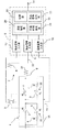
図1は、本発明に係るガス絶縁遮断器システムの第1の実施形態を示す模式的ブロック構成図である。また、図2は、図1の実施形態における主回路遮断時の主回路電流、補助開閉器および主接点の動作の一例を示すタイムチャートである。
[First Embodiment]
FIG. 1 is a schematic block diagram showing a first embodiment of a gas insulated circuit breaker system according to the present invention. FIG. 2 is a time chart showing an example of the operation of the main circuit current, the auxiliary switch, and the main contact when the main circuit is interrupted in the embodiment of FIG.
この抵抗付ガス絶縁遮断器1は、内部に絶縁ガスを封入した金属容器15内に配置されて主回路6の途中に接続された主接点2を含む。図示の例では、2個の主接点2が互いに直列に接続されている。各主接点2には、抵抗接点連接体30が各主接点2に並列に接続され、各抵抗接点連接体30は、抵抗体4と抵抗接点3とが互いに直列に接続されて構成されている。2組の主接点2および抵抗接点連接体30は一つの共通の金属容器15内に収納され、金属容器15には温度センサ16が取り付けられている。
This gas insulated circuit breaker 1 with resistance includes a
主接点2および抵抗接点3がすべて閉じているときに、上位システム(図示せず)から遮断指令が出されると、初めに二つの主接点2が開き、所定の時間遅れの後に二つの抵抗接点3が開くように構成されている。また、主接点2および抵抗接点3がすべて開いているときに、上位システムから投入指令が出されると、初めに二つの抵抗接点3が閉じ、所定の時間遅れの後に二つの主接点2が閉じるように構成されている。
When the
主回路の金属容器15外には変流器31を含む主回路電流計測回路7が配置され、この主回路電流計測回路7は図示しない保護リレーなどに接続されている。また、主回路電流計測回路7に補助変流器8が配置され、補助電流計測回路32が構成されている。
A main circuit
この抵抗付ガス絶縁遮断器1の近傍に信号処理装置9が配置されている。信号処理装置9は、接点信号入力部10と、電流信号入力部11と、温度信号入力部12と、演算/記憶部13を含んでいる。また、演算/記憶部13は、温度推定部20と、待機時間算出部21と記録部22とを含んでいる。
A
補助開閉器5は主接点2と連動して開閉し、補助開閉器5の接点信号は接点信号入力部10に入力されるようになっている。ここで入力された信号は接点信号入力部10によりディジタル信号に変換され、演算/記憶部13に入力されるようになっている。
The
補助変流器8から出力された主回路電流信号は、補助電流計測回路32を介して電流信号入力部11に入力され、内部でアナログ−ディジタル(A/D)変換され、演算/記憶部13に入力されるようになっている。
The main circuit current signal output from the
温度センサ16からの信号は温度信号入力部12に入力され、温度信号入力部12の内部でA/D変換され、演算/記憶部13に入力されるようになっている。さらに、演算/記憶部13と図示しない上位システムとは伝送路14により接続されている。
A signal from the
図2は、この実施形態において、演算/記憶部13にて記録された電流情報と、補助開閉器5の動作情報、主接点2の動作情報をグラフ化して示したものである。以下では、図2を用いて、抵抗付ガス絶縁遮断器監視システムの抵抗体4の温度上昇算出処理の動作・作用について詳細に説明する。
FIG. 2 is a graph showing the current information recorded in the calculation /
抵抗体4の温度上昇ΔTは次の(1)式により求めることができる。 The temperature rise ΔT of the resistor 4 can be obtained by the following equation (1).
ΔT = ∫{Ir(t)}2 dt・R/α …(1)
なお、上記(1)式において、Irは抵抗体の通電電流、Rは抵抗体の抵抗値、αは抵抗体の比熱比である。
ΔT = ∫ {Ir (t)} 2 dt · R / α (1)
In the above equation (1), Ir is an energization current of the resistor, R is a resistance value of the resistor, and α is a specific heat ratio of the resistor.
ここで、図2に示すように、遮断器が事故電流を遮断する場合の通電電流と、遮断器の主接点2等の変化の様子を示す。演算/記憶部13において、通電電流を所定の周波数でサンプリングし、遮断器主接点2が開離し、抵抗接点3に転流した以降(図2の斜線部分)の通電電流について、(1)式の積分を行なうことにより、抵抗体の温度上昇ΔTを計算する。転流のタイミングについては、主接点の補助開閉器5の信号変化から主接点2の開離タイミングを算出し、主接点2の開離タイミング以降で電流レベルが小さくなる前の零点を検出している。
Here, as shown in FIG. 2, the state of change of the energizing current and the
次に、抵抗体温度Tr0は以下の(2)式により求めることができる。 Next, the resistor temperature Tr0 can be obtained by the following equation (2).
Tr0 = Tamb + ΔT + β …(2)
なお、上記(2)式において、Tambは温度センサにより求めた金属容器温度、βは通電、直射日光により想定される温度上昇である。
Tr0 = Tamb + ΔT + β (2)
In the above equation (2), Tamb is the temperature of the metal container obtained by the temperature sensor, and β is the temperature rise assumed by energization and direct sunlight.
また、遮断器操作後の抵抗体温度Trの変化は、以下の(3)式により求めることができる。 Moreover, the change of the resistor temperature Tr after the circuit breaker operation can be obtained by the following equation (3).
Tr = ΔT・exp(−t/τ) + Tamb + β …(3)
なお、上記(3)式において、tは遮断器操作後の時間、τは抵抗体の冷却時定数である。
Tr = ΔT · exp (−t / τ) + Tamb + β (3)
In the above equation (3), t is the time after the breaker operation, and τ is the cooling time constant of the resistor.
これらの演算を行なうことにより、信号処理装置9の温度推定部20では、事故電流遮断後の抵抗体4の温度を推算することができる。さらに、待機時間算出部21で、次の操作が可能となるまでの待機時間を算出することができる。そして、これらの計算結果は記録部22に記録されるとともに、抵抗付ガス絶縁遮断器1の操作指令を出力する上位システムに対し、次の操作が可能となるまでの待機時間を、伝送路14を介して伝送データとして通知することが可能となる。
By performing these calculations, the
さらに、上位システムに対し、待機時間内の抵抗付ガス絶縁遮断器1の操作を禁止するための信号を出力する禁止信号出力部23を演算/記録部13に設けてもよい。
Furthermore, the calculation /
以上のように、本実施の形態では、高電圧が印加されている抵抗体の温度を直接計測する必要がなく、すなわち、遮断器本体の構造を変更することなく、抵抗体の温度を推定することができる。したがって、遮断器操作判断の合理化を図り、遮断器の信頼性向上を図ることができる。 As described above, in this embodiment, there is no need to directly measure the temperature of the resistor to which a high voltage is applied, that is, the temperature of the resistor is estimated without changing the structure of the breaker body. be able to. Therefore, the circuit breaker operation judgment can be rationalized and the reliability of the circuit breaker can be improved.
また、この実施形態では、主回路電流計測回路7に補助変流器8が配置され、補助変流器8から出力された主回路電流信号が、補助電流計測回路32を介して電流信号入力部11に入力される。そのため、電流信号入力部11側から主回路電流計測回路7への干渉が排除される。一般に主回路電流計測回路7は上位システムに主回路電流情報を伝えるための重要な回路であるから、この実施形態で、上位システムに伝えられる主回路電流情報が信号処理装置9によって干渉されないことは重要である。
In this embodiment, the auxiliary
[第2の実施形態]
図3は、本発明に係るガス絶縁遮断器システムの第2の実施形態を示す模式的ブロック構成図である。この実施形態では、補助開閉器5の信号および主回路電流計測回路7の信号が保護リレー装置17に送られる。そして、それらの信号に基づいて、主接点2の動作タイミング信号および主回路6の電流情報が保護リレー装置17から伝送路18を介して信号処理装置9の演算/記憶部13に入力されるように構成されている。
[Second Embodiment]
FIG. 3 is a schematic block diagram showing a second embodiment of the gas insulated circuit breaker system according to the present invention. In this embodiment, the signal of the
この実施形態では、補助変流器8や補助電流計測回路32が不要である。またこの実施形態では、主接点2の開閉動作のタイミングを表す接点信号(補助開閉器5の接点信号)および主回路6の電流を表す信号が保護リレー装置17でディジタル信号に変換され、ディジタル信号として伝送路18を介して信号処理装置9の演算/記憶部13に入力される。そのため、この実施形態の信号処理装置9には、第1の実施形態における接点信号入力部10や電流信号入力部11のようなアナログ−ディジタル変換機能が不要である。よってこの実施形態によれば、構成の簡素なシステムを提供することができる。
In this embodiment, the auxiliary
[他の実施形態]
以上説明した実施形態は単なる例示であって、本発明はこれらに限定されるものではない。たとえば、上記実施形態では、主接点2および抵抗接点連接体30を収容する金属容器15に温度センサ16を取り付けるものとしたが、温度センサ16は、この金属容器15に接続された他の容器または、この金属容器15近傍の他の構造物に取り付けてもよい。
[Other Embodiments]
The embodiments described above are merely examples, and the present invention is not limited to these. For example, in the above embodiment, the
1…抵抗付ガス絶縁遮断器
2…主接点
3…抵抗接点
4…抵抗体
5…補助開閉器
6…主回路
7…主回路電流計測回路
8…補助変流器
9…信号処理装置
10…接点信号入力部
11…電流信号入力部
12…温度信号入力部
13…演算/記憶部
14…伝送路
15…金属容器
16…温度センサ
17…保護リレー装置
20…温度推定部
21…待機時間算出部
22…記録部
23…禁止信号出力部
30…抵抗接点連接体
31…変流器
32…補助電流計測回路
DESCRIPTION OF SYMBOLS 1 ... Resistant gas insulated
Claims (9)
前記容器内に収容されて主回路を開閉する主接点と、
前記容器内に収容され、前記主接点に対して並列に接続されて、前記主接点が開いてから所定時間後に開き、前記主接点が閉じる所定時間前に閉じるように構成された抵抗接点と、
前記容器内に収容され、前記抵抗接点に直列に接続されてその抵抗接点と合わせて前記主接点に対して並列に接続された抵抗体と、
前記抵抗体周辺の温度を計測する温度センサと、
前記主接点の開閉動作のタイミングを表す接点信号と、前記主回路の電流を表す電流信号と、前記温度センサから出力される温度信号とに基づいて抵抗体温度を推定する温度推定部と、
を有することを特徴とするガス絶縁遮断器システム。 A container filled with insulating gas;
A main contact housed in the container for opening and closing the main circuit;
A resistance contact configured to be accommodated in the container and connected in parallel to the main contact, to open a predetermined time after the main contact opens, and to close a predetermined time before the main contact closes;
A resistor housed in the container, connected in series to the resistance contact, and connected in parallel to the main contact together with the resistance contact;
A temperature sensor for measuring the temperature around the resistor;
A temperature estimator for estimating a resistor temperature based on a contact signal indicating the timing of the opening and closing operation of the main contact, a current signal indicating the current of the main circuit, and a temperature signal output from the temperature sensor;
A gas insulated circuit breaker system comprising:
前記接点信号は、前記補助開閉器の開閉動作のタイミングを表す信号であること、を特徴とする請求項1ないし請求項3のいずれか一項に記載のガス絶縁遮断器システム。 An auxiliary switch that is arranged outside the container and opens and closes in conjunction with the opening and closing operation of the main contact;
4. The gas insulated circuit breaker system according to claim 1, wherein the contact signal is a signal representing a timing of an opening / closing operation of the auxiliary switch. 5.
前記主回路電流計測回路に取り付けられた補助変流器と、
をさらに有し、
前記電流信号は前記補助変流器の出力であること、を特徴とする請求項1ないし請求項6のいずれか一項に記載のガス絶縁遮断器システム。 A main circuit current measurement circuit, which is attached to the main circuit and connected to a protective relay that outputs a command to open the main contact, and measures the current of the main circuit;
An auxiliary current transformer attached to the main circuit current measurement circuit;
Further comprising
The gas insulated circuit breaker system according to any one of claims 1 to 6, wherein the current signal is an output of the auxiliary current transformer.
前記電流信号は前記保護リレーから入力されること、を特徴とする請求項1ないし請求項6のいずれか一項に記載のガス絶縁遮断器システム。 A main circuit current measuring circuit that is attached to the main circuit and connected to a protective relay that outputs an opening command of the main contact and measures the current of the main circuit;
The gas insulation circuit breaker system according to any one of claims 1 to 6, wherein the current signal is input from the protection relay.
前記容器内に収容されて主回路を開閉する主接点と、
前記容器内に収容され、前記主接点に対して並列に接続されて、前記主接点が開いてから所定時間後に開き、前記主接点が閉じる所定時間前に閉じるように構成された抵抗接点と、
前記容器内に収容され、前記抵抗接点に直列に接続されてその抵抗接点と合わせて前記主接点に対して並列に接続された抵抗体と、
を備えたガス絶縁遮断器を監視する方法であって、
前記主接点の開閉動作のタイミングを表す接点信号を入力する接点信号入力ステップと、
前記主回路の電流を表す電流信号を入力する主回路電流入力部ステップと、
前記抵抗体周辺の温度を計測する温度計測ステップと、
前記温度計測ステップで得られた温度信号を入力する温度信号入力ステップと、
前記接点信号と電流信号と温度信号とに基づいて抵抗体温度を推定する温度推定ステップと、
を有することを特徴とするガス絶縁遮断器監視方法。 A container filled with insulating gas;
A main contact housed in the container for opening and closing the main circuit;
A resistance contact configured to be accommodated in the container and connected in parallel to the main contact, to open a predetermined time after the main contact opens, and to close a predetermined time before the main contact closes;
A resistor housed in the container, connected in series to the resistance contact, and connected in parallel to the main contact together with the resistance contact;
A method of monitoring a gas insulated circuit breaker comprising:
A contact signal input step of inputting a contact signal representing the timing of the opening and closing operation of the main contact;
A main circuit current input unit step for inputting a current signal representing the current of the main circuit;
A temperature measuring step for measuring the temperature around the resistor;
A temperature signal input step for inputting the temperature signal obtained in the temperature measurement step;
A temperature estimating step for estimating a resistor temperature based on the contact signal, the current signal, and the temperature signal;
A gas insulated circuit breaker monitoring method comprising:
Priority Applications (4)
| Application Number | Priority Date | Filing Date | Title |
|---|---|---|---|
| JP2008274363A JP5166204B2 (en) | 2008-10-24 | 2008-10-24 | Gas insulated circuit breaker system and gas insulated circuit breaker monitoring method |
| US12/580,527 US8199445B2 (en) | 2008-10-24 | 2009-10-16 | Gas insulated circuit breaker system and gas insulated circuit breaker monitoring method |
| CN200910179467.6A CN101728783B (en) | 2008-10-24 | 2009-10-20 | Gas insulated circuit breaker system and gas insulated circuit breaker monitoring method |
| EP09013346.3A EP2180491B1 (en) | 2008-10-24 | 2009-10-22 | Gas insulated circuit breaker system and gas insulated circuit breaker monitoring method |
Applications Claiming Priority (1)
| Application Number | Priority Date | Filing Date | Title |
|---|---|---|---|
| JP2008274363A JP5166204B2 (en) | 2008-10-24 | 2008-10-24 | Gas insulated circuit breaker system and gas insulated circuit breaker monitoring method |
Publications (2)
| Publication Number | Publication Date |
|---|---|
| JP2010102995A JP2010102995A (en) | 2010-05-06 |
| JP5166204B2 true JP5166204B2 (en) | 2013-03-21 |
Family
ID=41508261
Family Applications (1)
| Application Number | Title | Priority Date | Filing Date |
|---|---|---|---|
| JP2008274363A Expired - Fee Related JP5166204B2 (en) | 2008-10-24 | 2008-10-24 | Gas insulated circuit breaker system and gas insulated circuit breaker monitoring method |
Country Status (4)
| Country | Link |
|---|---|
| US (1) | US8199445B2 (en) |
| EP (1) | EP2180491B1 (en) |
| JP (1) | JP5166204B2 (en) |
| CN (1) | CN101728783B (en) |
Families Citing this family (3)
| Publication number | Priority date | Publication date | Assignee | Title |
|---|---|---|---|---|
| WO2012119082A1 (en) | 2011-03-02 | 2012-09-07 | Franklin Fueling Systems, Inc. | Gas density monitoring system |
| CA2865094C (en) | 2012-02-20 | 2020-07-21 | Franklin Fueling Systems, Inc. | Moisture monitoring system |
| PL2700962T3 (en) * | 2012-08-24 | 2019-03-29 | Omicron Electronics Gmbh | Measurement of a resistance of a switch contact of an electrical circuit breaker |
Family Cites Families (23)
| Publication number | Priority date | Publication date | Assignee | Title |
|---|---|---|---|---|
| US3164705A (en) * | 1961-03-01 | 1965-01-05 | Westinghouse Electric Corp | Fluid-blast circuit interrupters with retractable impedance probe |
| DE1191015B (en) * | 1961-06-26 | 1965-04-15 | Asea Ab | Compressed air switch with damping resistor |
| US3452172A (en) * | 1965-07-12 | 1969-06-24 | Siemens Ag | Current limiting circuit breaker |
| US3538278A (en) * | 1968-06-13 | 1970-11-03 | Gen Electric | High voltage electric circuit breaker |
| US4035692A (en) * | 1975-11-20 | 1977-07-12 | Cutler-Hammer, Inc. | Resistor protection systems |
| US4069406A (en) * | 1975-12-02 | 1978-01-17 | Allis-Chalmers Corporation | Closing resistor switch for gas insulated circuit breaker |
| FR2512267A1 (en) * | 1981-08-26 | 1983-03-04 | Alsthom Atlantique | COMPRESSED GAS CIRCUIT BREAKER WITH OPENING AND CLOSING RESISTORS |
| JPS6155829A (en) * | 1984-08-28 | 1986-03-20 | 株式会社東芝 | Breaker |
| JPH0244816U (en) * | 1988-09-22 | 1990-03-28 | ||
| FR2674064B1 (en) * | 1991-03-13 | 1993-06-04 | Alsthom Gec | VARISTOR AND RESISTANCE DEVICE FOR THE CIRCUIT BREAKER OF A CIRCUIT BREAKER. |
| JPH05101907A (en) * | 1991-03-30 | 1993-04-23 | Toshiba Corp | Breaker for electric power and resistor for electric power |
| JPH0541302A (en) | 1991-08-06 | 1993-02-19 | Hitachi Ltd | Bulk type of linear resistor and manufacture of same |
| JPH06141460A (en) * | 1992-10-27 | 1994-05-20 | Central Japan Railway Co | Protective relay device |
| DE19547098A1 (en) * | 1995-12-16 | 1997-06-19 | Asea Brown Boveri | Power switch with arc-quenching chamber and switch-on resistor |
| JP3887438B2 (en) * | 1996-11-01 | 2007-02-28 | 株式会社東芝 | Substation equipment |
| US6072673A (en) * | 1998-11-19 | 2000-06-06 | Square D Company | Medium to high voltage load circuit interrupters including metal resistors having a positive temperature coefficient of resistivity (PTC elements) |
| EP1604440B1 (en) * | 2003-03-14 | 2016-06-15 | ABB Technology AG | Electronic circuit breaker |
| JP4108614B2 (en) * | 2004-01-13 | 2008-06-25 | 三菱電機株式会社 | Phase control switchgear |
| CN2701141Y (en) * | 2004-05-31 | 2005-05-18 | 曹志伟 | Protecting device for on-off coil of circuit breaker |
| JP4724003B2 (en) * | 2006-01-10 | 2011-07-13 | 株式会社日本Aeパワーシステムズ | Gas insulated switchgear |
| FR2896335B1 (en) * | 2006-01-17 | 2008-11-14 | Areva T & D Sa | GENERATOR CIRCUIT BREAKER WITH INSERTED RESISTANCE |
| US7869170B2 (en) * | 2006-07-14 | 2011-01-11 | Susan Jean Walker Colsch | Method and system for time synchronized trip algorithms for breaker self protection |
| JP5116607B2 (en) * | 2008-08-18 | 2013-01-09 | 株式会社日立製作所 | Gas circuit breaker |
-
2008
- 2008-10-24 JP JP2008274363A patent/JP5166204B2/en not_active Expired - Fee Related
-
2009
- 2009-10-16 US US12/580,527 patent/US8199445B2/en not_active Expired - Fee Related
- 2009-10-20 CN CN200910179467.6A patent/CN101728783B/en not_active Expired - Fee Related
- 2009-10-22 EP EP09013346.3A patent/EP2180491B1/en not_active Not-in-force
Also Published As
| Publication number | Publication date |
|---|---|
| US8199445B2 (en) | 2012-06-12 |
| CN101728783A (en) | 2010-06-09 |
| JP2010102995A (en) | 2010-05-06 |
| CN101728783B (en) | 2013-03-20 |
| US20100102036A1 (en) | 2010-04-29 |
| EP2180491B1 (en) | 2014-06-18 |
| EP2180491A1 (en) | 2010-04-28 |
Similar Documents
| Publication | Publication Date | Title |
|---|---|---|
| JP5606651B1 (en) | Power switching control device and opening control method | |
| EP2843791B1 (en) | Protection device for electricity supply circuit | |
| JP5166204B2 (en) | Gas insulated circuit breaker system and gas insulated circuit breaker monitoring method | |
| JP2009531010A5 (en) | ||
| CN102576997A (en) | Power supply control device | |
| CN101640406A (en) | Arc flash detection system, apparatus and method | |
| KR101904578B1 (en) | Device and method for protecting a load | |
| EP3262669B1 (en) | Improvements in or relating to digital output circuits | |
| US20200350642A1 (en) | Method for early detection of an imminent overheating of at least one battery cell of a battery, detection device, and motor vehicle | |
| JP3127768B2 (en) | Monitoring method of electric wire temperature | |
| JP3743479B2 (en) | Circuit breaker switching control device | |
| JP4888322B2 (en) | Digital protective relay device | |
| JP2002238147A (en) | Temperature calculation type overload protective relay | |
| US9325165B2 (en) | Device and method for protecting a consumer | |
| JP5031051B2 (en) | Circuit breaker monitoring device and detection method of circuit breaker monitoring device | |
| US9520707B2 (en) | Device for protecting a user | |
| KR102038259B1 (en) | Protection of transformers with tap changers | |
| JPH081859B2 (en) | Tap switching device under load | |
| JP5468461B2 (en) | Circuit breaker monitoring device and circuit breaker monitoring control system | |
| JP2012130141A (en) | Monitoring device | |
| RU2335837C1 (en) | Automatic circuit breaker overload protection device | |
| JP3128989B2 (en) | Temperature measurement device | |
| JP2006271030A (en) | Central monitor for monitoring receiving/distributing equipment, and its monitoring recording method | |
| JP5949664B2 (en) | Resistor failure detection device for CR suppressor of substation equipment | |
| JPH05180700A (en) | Temperature measuring device |
Legal Events
| Date | Code | Title | Description |
|---|---|---|---|
| RD04 | Notification of resignation of power of attorney |
Free format text: JAPANESE INTERMEDIATE CODE: A7424 Effective date: 20110421 |
|
| A621 | Written request for application examination |
Free format text: JAPANESE INTERMEDIATE CODE: A621 Effective date: 20110705 |
|
| A977 | Report on retrieval |
Free format text: JAPANESE INTERMEDIATE CODE: A971007 Effective date: 20121116 |
|
| TRDD | Decision of grant or rejection written | ||
| A01 | Written decision to grant a patent or to grant a registration (utility model) |
Free format text: JAPANESE INTERMEDIATE CODE: A01 Effective date: 20121127 |
|
| A61 | First payment of annual fees (during grant procedure) |
Free format text: JAPANESE INTERMEDIATE CODE: A61 Effective date: 20121220 |
|
| FPAY | Renewal fee payment (event date is renewal date of database) |
Free format text: PAYMENT UNTIL: 20151228 Year of fee payment: 3 |
|
| R150 | Certificate of patent or registration of utility model |
Free format text: JAPANESE INTERMEDIATE CODE: R150 |
|
| LAPS | Cancellation because of no payment of annual fees |