EP0779565B1 - Filterung mit konstanter Verzögerung für synchronisierte Mehrachsenantriebe - Google Patents
Filterung mit konstanter Verzögerung für synchronisierte Mehrachsenantriebe Download PDFInfo
- Publication number
- EP0779565B1 EP0779565B1 EP96308295A EP96308295A EP0779565B1 EP 0779565 B1 EP0779565 B1 EP 0779565B1 EP 96308295 A EP96308295 A EP 96308295A EP 96308295 A EP96308295 A EP 96308295A EP 0779565 B1 EP0779565 B1 EP 0779565B1
- Authority
- EP
- European Patent Office
- Prior art keywords
- servo loop
- constant delay
- filter
- response curve
- axis
- Prior art date
- Legal status (The legal status is an assumption and is not a legal conclusion. Google has not performed a legal analysis and makes no representation as to the accuracy of the status listed.)
- Expired - Lifetime
Links
Images
Classifications
-
- G—PHYSICS
- G05—CONTROLLING; REGULATING
- G05B—CONTROL OR REGULATING SYSTEMS IN GENERAL; FUNCTIONAL ELEMENTS OF SUCH SYSTEMS; MONITORING OR TESTING ARRANGEMENTS FOR SUCH SYSTEMS OR ELEMENTS
- G05B19/00—Program-control systems
- G05B19/02—Program-control systems electric
- G05B19/18—Numerical control [NC], i.e. automatically operating machines, in particular machine tools, e.g. in a manufacturing environment, so as to execute positioning, movement or co-ordinated operations by means of program data in numerical form
- G05B19/416—Numerical control [NC], i.e. automatically operating machines, in particular machine tools, e.g. in a manufacturing environment, so as to execute positioning, movement or co-ordinated operations by means of program data in numerical form characterised by control of velocity, acceleration or deceleration
-
- G—PHYSICS
- G05—CONTROLLING; REGULATING
- G05B—CONTROL OR REGULATING SYSTEMS IN GENERAL; FUNCTIONAL ELEMENTS OF SUCH SYSTEMS; MONITORING OR TESTING ARRANGEMENTS FOR SUCH SYSTEMS OR ELEMENTS
- G05B2219/00—Program-control systems
- G05B2219/30—Nc systems
- G05B2219/41—Servomotor, servo controller till figures
- G05B2219/41187—Inverse, reciprocal filter, transfer function, reduce lag in contouring
-
- G—PHYSICS
- G05—CONTROLLING; REGULATING
- G05B—CONTROL OR REGULATING SYSTEMS IN GENERAL; FUNCTIONAL ELEMENTS OF SUCH SYSTEMS; MONITORING OR TESTING ARRANGEMENTS FOR SUCH SYSTEMS OR ELEMENTS
- G05B2219/00—Program-control systems
- G05B2219/30—Nc systems
- G05B2219/41—Servomotor, servo controller till figures
- G05B2219/41192—Compensation for different response times, delay of axis
-
- G—PHYSICS
- G05—CONTROLLING; REGULATING
- G05B—CONTROL OR REGULATING SYSTEMS IN GENERAL; FUNCTIONAL ELEMENTS OF SUCH SYSTEMS; MONITORING OR TESTING ARRANGEMENTS FOR SUCH SYSTEMS OR ELEMENTS
- G05B2219/00—Program-control systems
- G05B2219/30—Nc systems
- G05B2219/50—Machine tool, machine tool null till machine tool work handling
- G05B2219/50216—Synchronize speed and position of several axis, spindles
Definitions
- This invention relates generally to linear feedback servo control systems and more particularly concerns such control systems as applied to the generation of ophthalmic lenses.
- substantially linear feedback control systems equipped with a linear servo algorithm such as a proportional integral derivative or PID loop
- feed forward terms are introduced to minimize following error during continuous motion.
- These systems frequently employ both velocity feed forward and acceleration feed forward terms to obtain accuracy as close to ideal as possible for the intended bandwidth of motion.
- the ideal condition for best accuracy would be to have a zero phase response or lag and an amplitude response of unity or 0dB throughout the bandwidth of intended motion for that axis.
- the phase response can be tuned by adjusting the feed forward parameters so that, at lower frequencies, approximately no phase lag is observed. When this is done, the amplitude response often resembles a high pass or sometimes a low pass filter. However, the amplitude response at the very lowest frequencies will be approximately unity or 0dB.
- each axis has good phase response at lower frequencies but has an amplitude response resembling a filter.
- the filter characteristics for the amplitude response of each axis are different. Quite often, it is required that one, or several, of the synchronized axes have motion at higher than the very lowest frequencies where, as stated above, the amplitude response of each axis is already approximately unity. Typically, this is the case for mechanisms involving a fast tool servo.
- the amplitude response of the fast moving axes should be altered to be approximately equal to unity in the intended motion bandwidth for those axes while at the same time maintaining approximately zero phase lag for all synchronized axes in their respective intended motion bandwidths.
- US Patent No. 5,194,790 discloses a control device for controlling and driving a plurality of servo motors to move an object to a predetermined position in a mechanical coordinate system.
- US Patent No. 4,694,414 discloses a two point linear interpolation filter which imparts delay to a digital input signal proportional to the value of a delay control signal. Errors in both the amplitude and the phase of the delayed signal are minimized by the addition of a correction signal to the delayed signal.
- US Patent No. 4,992,714 discloses a band pass filter device and a method of filtering using such a device, in particular for control of a rotor. It is, therefore, an object of this invention to provide a multiple axis linear feedback servo control system suitable for the generation of an ophthalmic lens. Another object of this invention is to provide a multiple axis linear feedback servo control system which coordinates the phase responses of the synchronized motion axes. A further object of this invention is to provide a multiple axis linear feedback servo control system which applies similar filter characteristics to the servo mechanisms controlling the synchronized motion axes.
- a further object of this invention is to provide a multiple axis linear feedback servo control system which alters the amplitude response of fast moving axes to improve accuracy over the intended motion bandwidth. And, it is an object of this invention to provide a multiple axis linear feedback servo control system which maintains an approximately zero phase lag for all synchronized motion axes when the amplitude response of the fast moving axes have been altered to improve accuracy over the intended motion bandwidth.
- the invention provides a constant delay filter system for synchronizing motion on multiple axes in a linear feedback servo control system according to claim 1 of the appended claims.
- the invention further provides a method of synchronizing motion on multiple axes in a linear feedback servo control system according to claim 5 of the appended claims.
- a linear feedback servo control system in which the motion profile for each axis is pre-filtered before it is introduced to the servo loop for that axis.
- the motion profile is pre-filtered by a filter having an inverse amplitude response to the amplitude response of the servo loop. Therefore, the composite amplitude response of the filter/servo loop combination is approximately ideal for all relevant frequencies.
- the pre-filtering is done using constant delay filters, whether high pass, low pass or hybrid, that exhibit a phase lag corresponding to a time delay that is essentially constant at all relevant frequencies.
- Each axis of synchronized motion is pre-filtered with constant delay filters having the same time delay constant, but selected so that the motion of each axis provides sufficient accuracy within the intended bandwidth of that particular axis. Consequently, while phase lag is not zero, there is essentially constant delay for all axes at all relevant frequencies. Therefore, synchronized motion is preserved because motion in all axes is delayed by a constant amount.
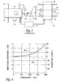
- FIG. 1 a synchronized multiple axis motion application for generation of ophthalmic lenses is illustrated.
- the lens 11 is mounted for rotation on a spindle 13 which is driven about its axis of the rotation R by a drive mechanism 15 supported on a mount 17.
- the spindle 13 as shown rotates in a clockwise direction looking at the face of the lens 11 to be generated.
- the mount 17 translates along a Y axis, as shown on tracks 19 in response to another drive mechanism 21, such as a motor driving a worm gear.
- the lathing tool 23 is located on another mount 25 which moves reciprocally in the direction of the X axis in response to a third drive mechanism 27 such as an electric motor connected to a worm gear. As shown, the tool mount 25 reciprocates on tracks 29.
- a third drive mechanism 27 such as an electric motor connected to a worm gear.
- the tool mount 25 reciprocates on tracks 29.
- the operation of the three drive mechanisms 15, 21 and 27 must be synchronized so that the combined motion of the tool 23 and the lens 11 provide an accurate prescription topography. If the lens prescription defines a toric topography, one revolution of the lens 11 will occur simultaneously with one interval of translation of the lens mount 17. However, in that same revolution, the lathing tool mount 25 will experience two full cycles of reciprocation.
- the operation of the system is controlled by a computer 31.
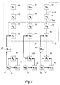
- FIG. 2 a preferred embodiment of a servo control system for synchronizing motion on the X, Y and R axes is illustrated.
- the operation of the rotational drive motor 15 is controlled by a rotational servo loop 41 which feeds a signal to the rotational amplifier 43 which in turn controls the operation of the rotational drive motor 15.
- a feedback signal from the rotational drive motor 15 is fed from the rotational encoder 45 back to the amplifier 43 which in turn feeds the feedback signal to the rotational servo loop 41.
- a lens servo loop 61 provides a control signal via a lens amplifier 63 to control the lens drive motor 21, causing translation of the lens 11 in the Y axis.
- a feedback signal derived from the lens drive motor 21 is fed from an encoder 65 to the lens amplifier 63.
- another encoder 67 receives a mechanical signal from the lens mount 17 for feedback to the lens servo loop 61.
- the tool servo loop 81 controls the tool drive motor 27 through a tool amplifier 83, a feedback signal being fed from the tool drive motor 27 through an encoder 85 and back to the tool amplifier 83.
- a tool encoder 87 receives a mechanical signal from the tool mount 25 for feedback to the tool servo loop 81.
- Each of the servo loops 41, 61 and 81 are preferably proportional integral derivative or PID controllers, though other types of loops such as pole placement filters could be employed.
- Each of these servo loops 41, 61 and 81 employs velocity feed forward and acceleration feed forward parameters and is tuned to obtain optimal accuracy for the intended bandwidth of motion.
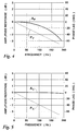
- the response curves A T and P T are determined with respect to the frequency of the tool 23 because the tool 23 traces a relatively assymetric surface and travels at relatively higher frequencies. Consequently, if the tool amplitude response A T can be brought to unity or zero decibels in the desired frequency range, accurate synchronization of the lens axes of rotational and translating motion can be accomplished as well.
- the amplitude and phase lag curves A T and P T for the tool servo loop 81 are determined by graphically representing a ratio of the tool servo loop output data to input data, or Bode plot, for input signals over the desired range of frequencies. This results in the curves illustrated in Figure 3. From this it can be seen that, if the input signal to the tool servo loop 81 is filtered in a filter system having an amplitude response curve that is an inversion reflection of the tool servo loop curve A T , then the filter system characteristics will, when combined with the servo loop characteristics, result in a substantially unity or 0dB amplitude response across the desired range of frequencies.
- the computer 31 calculates the tool path data for the movement of the lens 11 in the Y and R axes and the tool 23 in the X axis.
- the computer 31 upon request for topography data respecting a particular prescriptive lens 11, the computer 31 generates a stream of tool data 89 which is received by a tool data filter 91.
- the tool data filter 91 preferably a cascade of filters operating over the desired frequency range to allow for better control of the system, uses constant delay filters in which the phase lag is substantially constant at all relevant frequencies.
- the tool filter 91 is defined by the equations: where I FT is the output of the tool filter 91, I 3 is the input to the tool filter 91 representative of the tool position at an instant in time, I 2 is the input to the tool filter 91 representative of the position of the tool at the next preceding instant of time and I 1 is the input to the tool filter 91 representative ofthe position of the tool at the next-next preceding instant of time. ⁇ , ⁇ and 6 are constants.
- ⁇ can be varied until the amplitude response curve A F of the tool filter 91 is an inversion or reflection of the amplitude response curve A T of the tool servo loop 81, as is shown in Figure 4.
- the desired amplitude response curve A F causes a constant phase lag P F due to the tool filter 91. Consequently, the tool servo loop 81 will control the operation of the tool drive motor 27 in accordance with a corrected amplitude response curve A C as illustrated in Figure 5, but with the constant phase lag curve T C corresponding to the phase lag curve P F of the tool filter 91.
- all of the motion axes are brought into synchronized operation by incorporating similar or identical constant delay filters 51 and 71 to receive the rotational and translational data streams 49 and 69, respectively, from the computer 31.
- the lens rotation filter 51 and lens translation filter 71 are selected to have substantially identical phase lag characteristic curves as the corrected phase lag characteristic curve P C of the tool servo loop 81. Consequently, the rotational and translational servo loops 41 and 61 for the lens 11 will operate in the same phase lag relationship as the tool servo loop 81, resulting in synchronization of the system.
- the servo system is completed by use of trajectory calculators 53, 73 and 93 which receive topography data from their respective filters 51, 71 and 91 at a relatively low rate of speed, for example, in a range of 3 milliseconds per data point, and interpolates so as to output a data stream to their respective servo loops 41, 61 and 81 at a relatively high speed, for example, in a range of approximately 0.1 milliseconds per data point.
- the data defining the lens topography for each motion axis and defining the constant delay filters 51, 71 and 91 are preferably stored in the memory of the computer 31.
- the servo loops 41, 61 and 81 and the trajectory calculators 53, 73 and 93 are preferably part of a motion control card 33 contained in the computer 31. While sufficient accuracy of the application above described has been achieved by using identical filters 51, 71 and 91, in some applications it may be desirable to empirically match the amplitude response curve of each filter to the servo loop with which it is associated, provided, of course, the phase lag response is maintained substantially identical to the phase lag response of the higher frequency motion axis servo loop.
- phase lag curves of servo loops serving multiple motion axes after correcting the higher frequency axis servo loop amplitude curve to a unity or 0 decibel level, a synchronized, improved-accuracy, multi-axis motion system is achieved.
- the above principle can be applied in multi-axis systems having more than one axis moving at higher frequencies.
- the process of inverting the amplitude response of the servo loop of each of the high frequency axes is repeated, provided that the time delay for all constant delay filters are substantially identical.
Landscapes
- Engineering & Computer Science (AREA)
- Human Computer Interaction (AREA)
- Manufacturing & Machinery (AREA)
- Physics & Mathematics (AREA)
- General Physics & Mathematics (AREA)
- Automation & Control Theory (AREA)
- Control Of Position Or Direction (AREA)
- Numerical Control (AREA)
Claims (5)
- Filtersystem mit konstanter Verzögerung zum Synchronisieren der Bewegung auf mehreren Achsen in einem linearen Rückkopplungs-Servo-Steuerungssystem, in welchem eine erste Servoschleife (81) den Betrieb eines ersten Antriebsmechanismus (27) steuert, der eine Bewegung auf einer Achse mit relativ hohen Frequenzen bewirkt, und eine zweite Servoschleife (41 oder 61) den Betrieb eines zweiten Antriebsmechanismus (15 oder 21) steuert, der eine Bewegung auf einer anderen Achse mit relativ niedrigen Frequenzen bewirkt, dadurch gekennzeichnet, daß das System folgende Bestandteile umfaßt:ein erstes Filter (91) mit konstanter Verzögerung, das ein Eingangssignal für die erste Servoschleife (81) filtert und eine Amplituden-Ansprechcharakteristik besitzt, die im Wesentlichen eine Inversion der Amplituden-Ansprechcharakteristik der ersten Servoschleife (81) über die relativ hohen Frequenzen darstellt, undein zweites Filter (51 oder 71) mit konstanter Verzögerung, welches ein Eingangssignal für die zweite Servoschleife (41 oder 61) filtert und eine Phasenverzögerungs-Ansprechcharakteristik besitzt, die im Wesentlichen die gleiche ist wie die Phasenverzögerungs-Ansprechcharakteristik des ersten Filters (91) mit konstanter Verzögerung.
- System nach Anspruch 1 dadurch gekennzeichnet, daß das zweite Filter (51 oder 71) mit konstanter Verzögerung im Wesentlichen identisch mit dem ersten Filter (91) mit konstanter Verzögerung ist.
- System nach Anspruch 1 für ein lineares Rückkopplungs-Servo-Steuerungssystem, das eine dritte Servoschleife (61 oder 41) umfaßt, welche den Betrieb eines dritten Antriebsmechanismus (21 oder 15) steuert, der eine Bewegung auf einer dritten Achse mit relativ niedrigen Frequenzen bewirkt, wobei das System weiterhin ein drittes Filter (71 oder 51) mit konstanter Verzögerung aufweist, welches ein Eingangssignal für die dritte Servoschleife (61 oder 41) filtert und eine Phasenverzögerungs-Ansprechcharakteristik besitzt, die im Wesentlichen die gleiche ist wie die Phasen verzögerungs-Ansprechcharakteristik des ersten Filters (91) mit konstanter Verzögerung.
- System nach Anspruch 1, dadurch gekennzeichnet, daß das erste Filter (91) mit konstanter Verzögerung durch die Gleichungen
- Verfahren zum Synchronisieren der Bewegung auf mehreren Achsen in einem linearen Rückkopplungs-Servo-Steuerungssystem, bei welchem eine erste Servoschleife (81) den Betrieb eines ersten Antriebsmechanismus (27) steuert, der eine Bewegung auf einer Achse mit relativ hohen Frequenzen bewirkt, und eine zweite Servoschleife (41 oder 61) den Betrieb eines zweiten Antriebsmechanismus (15 oder 21) steuert, der eine Bewegung auf einer anderen Achse mit relativ niedrigen Frequenzen bewirkt, dadurch gekennzeichnet, daß das Verfahren folgende Schritte umfaßt:Ermitteln der Amplituden-Ansprechcharakteristik der ersten Servoschleife (81),Filtern eines Eingangssignals für die erste Servoschleife (81) unter Verwendung eines Filters (91) mit konstanter Verzögerung, das eine Amplituden-Ansprechcharakteristik besitzt, die im Wesentlichen eine Inversion der Amplituden-Ansprechcharakteristik der ersten Servoschleife ist,Ermitteln der Phasenverzögerungs-Ansprechcharakteristik des ersten Filters (91)mit konstanter Verzögerung undFiltem eines Eingangssignals für die zweite Servoschleife (41 oder 61) unter Verwendung eines zweiten Filters (51 oder 71) mit konstanter Verzögerung, das eine Phasenverzögerungs-Ansprechcharakteristik besitzt, die im Wesentlichen identisch mit der Ansprechcharakteristik des ersten Filters mit konstanter Verzögerung ist.
Applications Claiming Priority (2)
| Application Number | Priority Date | Filing Date | Title |
|---|---|---|---|
| US571443 | 1984-01-17 | ||
| US08/571,443 US5625267A (en) | 1995-12-13 | 1995-12-13 | Constant delay filtering for synchronized motion on multiple axes |
Publications (3)
| Publication Number | Publication Date |
|---|---|
| EP0779565A2 EP0779565A2 (de) | 1997-06-18 |
| EP0779565A3 EP0779565A3 (de) | 1997-12-29 |
| EP0779565B1 true EP0779565B1 (de) | 2001-06-27 |
Family
ID=24283721
Family Applications (1)
| Application Number | Title | Priority Date | Filing Date |
|---|---|---|---|
| EP96308295A Expired - Lifetime EP0779565B1 (de) | 1995-12-13 | 1996-11-15 | Filterung mit konstanter Verzögerung für synchronisierte Mehrachsenantriebe |
Country Status (3)
| Country | Link |
|---|---|
| US (1) | US5625267A (de) |
| EP (1) | EP0779565B1 (de) |
| DE (1) | DE69613547T2 (de) |
Families Citing this family (14)
| Publication number | Priority date | Publication date | Assignee | Title |
|---|---|---|---|---|
| US7437980B2 (en) * | 2002-05-29 | 2008-10-21 | Massachusetts Institute Of Technology | Flux-biased electromagnetic fast tool servo systems and methods |
| US7574947B2 (en) * | 2002-05-29 | 2009-08-18 | Massachusetts Institute Of Technology | Rotary fast tool servo system and methods |
| US7765905B2 (en) * | 2002-05-29 | 2010-08-03 | Massachusetts Institute Of Technology | Magnetic micropositioner and method of providing the same |
| US7275468B2 (en) * | 2002-05-29 | 2007-10-02 | Massachusetts Institute Of Technology | Rotary fast tool servo system and methods |
| US6845287B2 (en) * | 2002-11-20 | 2005-01-18 | Asml Holding N.V. | Method, system, and computer program product for improved trajectory planning and execution |
| US7146242B2 (en) * | 2003-09-30 | 2006-12-05 | Rockwell Automation Technologies, Inc. | Method and system for generating multi-dimensional motion profiles |
| US7180253B2 (en) | 2003-09-30 | 2007-02-20 | Rockwell Automation Technologies, Inc. | Method and system for generating multi-dimensional motion profiles |
| WO2005043266A2 (en) * | 2003-10-31 | 2005-05-12 | Massachusetts Institute Of Technology | Variable reluctance fast positioning system and methods |
| CA2455689A1 (en) * | 2004-01-23 | 2005-07-23 | Stuart Energy Systems Corporation | System for controlling hydrogen network |
| CN101937193A (zh) * | 2010-07-30 | 2011-01-05 | 东南大学 | 一种多内模并联型重复控制器及控制方法 |
| US8392002B2 (en) * | 2010-10-14 | 2013-03-05 | Delta Tau Data Systems, Inc. | Hybrid machine control incorporating fast-tool servos |
| CN102176115B (zh) * | 2011-01-25 | 2012-11-28 | 东南大学 | 一种特定类谐波重复控制器及控制方法 |
| CN104704147B (zh) | 2012-05-28 | 2017-06-30 | 水吉能公司 | 电解器与能量系统 |
| US10268183B2 (en) * | 2015-03-04 | 2019-04-23 | Omron Corporation | Control device and method of synchronizing control |
Family Cites Families (13)
| Publication number | Priority date | Publication date | Assignee | Title |
|---|---|---|---|---|
| US4386407A (en) * | 1980-08-11 | 1983-05-31 | The Bendix Corporation | Lathe control system |
| US4695960A (en) * | 1984-11-26 | 1987-09-22 | Siemens Aktiengesellschaft | Method and apparatus for numerical control of machine tools |
| US4694414A (en) * | 1984-12-19 | 1987-09-15 | Rca Corporation | Digital delay interpolation filter with amplitude and phase compensation |
| EP0228007B1 (de) * | 1985-12-28 | 1992-04-15 | Paul Forkardt GmbH & Co. KG | Werkzeugmaschine und deren Betriebsverfahren |
| JP2776871B2 (ja) * | 1989-03-01 | 1998-07-16 | 株式会社日立製作所 | フーリエ変換バンドパスフイルタ形制御装置 |
| JP2700819B2 (ja) * | 1989-05-24 | 1998-01-21 | ファナック株式会社 | タッピング方法 |
| JPH03263208A (ja) * | 1990-03-14 | 1991-11-22 | Brother Ind Ltd | サーボモータ制御装置 |
| US5235540A (en) * | 1990-04-26 | 1993-08-10 | Silicon Systems, Inc. | Parasitic insensitive programmable biquadratic pulse slimming technique |
| JP3049793B2 (ja) * | 1991-03-04 | 2000-06-05 | 松下電器産業株式会社 | 流体回転装置 |
| US5245565A (en) * | 1991-07-31 | 1993-09-14 | International Microelectronic Products | Digitally programmable linear phase filter having phase equalization |
| US5463603A (en) * | 1992-03-18 | 1995-10-31 | Imp, Inc. | Computer disk drive integrated data path circuit optimized for handling both data and servo signals |
| FR2689261A1 (fr) * | 1992-03-24 | 1993-10-01 | Atg Sa | Dispositif de commande destiné à asservir un objet à une position donnée. |
| EP0676681B1 (de) * | 1994-04-04 | 1999-11-10 | Kabushiki Kaisha Meidensha | Gerät zur Trägheitsverringerungsregelung zur Unterdrückung axialer Torsionsschwingungen eines Zweimassenresonanzsystems |
-
1995
- 1995-12-13 US US08/571,443 patent/US5625267A/en not_active Expired - Fee Related
-
1996
- 1996-11-15 DE DE69613547T patent/DE69613547T2/de not_active Expired - Fee Related
- 1996-11-15 EP EP96308295A patent/EP0779565B1/de not_active Expired - Lifetime
Also Published As
| Publication number | Publication date |
|---|---|
| EP0779565A2 (de) | 1997-06-18 |
| DE69613547T2 (de) | 2002-04-18 |
| DE69613547D1 (de) | 2001-08-02 |
| EP0779565A3 (de) | 1997-12-29 |
| US5625267A (en) | 1997-04-29 |
Similar Documents
| Publication | Publication Date | Title |
|---|---|---|
| EP0779565B1 (de) | Filterung mit konstanter Verzögerung für synchronisierte Mehrachsenantriebe | |
| EP1120698B1 (de) | Positionssteuerung | |
| EP0559397B1 (de) | Gerät zur genauen Positionierung | |
| EP1814000B1 (de) | Steuerung für elektrischen Motor | |
| US6252368B1 (en) | Numerically controlled system and backlash compensation device for use with the system | |
| EP1967924A1 (de) | Gerät zur synchron Steuerung mehrerer Servomotoren | |
| EP1439440A2 (de) | Steuervorrichtung für ein Servomotor | |
| US9459598B2 (en) | Motor control device | |
| US5359520A (en) | Adaptive error correction control system for optimizing mirror positioning in a spatial chopping or scanning telescope | |
| JPH1124754A (ja) | サーボ調整方法およびその装置 | |
| US5105137A (en) | Numerical control device for a grinding machine | |
| JP2006216051A (ja) | 未加工品と工作機械の工具との間の相対運動の運動分割方法 | |
| CA2057237C (en) | Sliding mode control system | |
| US20030125831A1 (en) | Controller for machining gears | |
| EP0961187A1 (de) | Steuerungseinheit für Maschine | |
| EP0396749B1 (de) | Regelungssystem für servomotor | |
| GB2281639A (en) | Machine tool position synchronization | |
| CN109388099B (zh) | 利用模型支持的误差补偿对工件的加工 | |
| WO2002037168A2 (en) | Method and system for producing progressive addition spectacle lenses | |
| US20030060902A1 (en) | Methods and systems for torque ripple compensation | |
| US5015935A (en) | Servo-control apparatus | |
| US20060210370A1 (en) | Thread cutting control method and thread cutting controller | |
| JP2907164B2 (ja) | 数値制御装置 | |
| HK1047184B (zh) | 偏心率补偿装置 | |
| EP1369732A2 (de) | Systemerkennung zur Verbesserung der Kontrolle eines mikroelektrischen mechanischen Spiegels |
Legal Events
| Date | Code | Title | Description |
|---|---|---|---|
| PUAI | Public reference made under article 153(3) epc to a published international application that has entered the european phase |
Free format text: ORIGINAL CODE: 0009012 |
|
| AK | Designated contracting states |
Kind code of ref document: A2 Designated state(s): DE FR GB NL |
|
| PUAL | Search report despatched |
Free format text: ORIGINAL CODE: 0009013 |
|
| AK | Designated contracting states |
Kind code of ref document: A3 Designated state(s): DE FR GB NL |
|
| 17P | Request for examination filed |
Effective date: 19980625 |
|
| 17Q | First examination report despatched |
Effective date: 19991112 |
|
| GRAG | Despatch of communication of intention to grant |
Free format text: ORIGINAL CODE: EPIDOS AGRA |
|
| GRAG | Despatch of communication of intention to grant |
Free format text: ORIGINAL CODE: EPIDOS AGRA |
|
| GRAH | Despatch of communication of intention to grant a patent |
Free format text: ORIGINAL CODE: EPIDOS IGRA |
|
| RAP1 | Party data changed (applicant data changed or rights of an application transferred) |
Owner name: COBURN OPTICAL INDUSTRIES, INC. |
|
| GRAH | Despatch of communication of intention to grant a patent |
Free format text: ORIGINAL CODE: EPIDOS IGRA |
|
| GRAA | (expected) grant |
Free format text: ORIGINAL CODE: 0009210 |
|
| RAP1 | Party data changed (applicant data changed or rights of an application transferred) |
Owner name: GERBER COBURN OPTICAL, INC. |
|
| AK | Designated contracting states |
Kind code of ref document: B1 Designated state(s): DE FR GB NL |
|
| REF | Corresponds to: |
Ref document number: 69613547 Country of ref document: DE Date of ref document: 20010802 |
|
| ET | Fr: translation filed | ||
| REG | Reference to a national code |
Ref country code: GB Ref legal event code: IF02 |
|
| PLBE | No opposition filed within time limit |
Free format text: ORIGINAL CODE: 0009261 |
|
| STAA | Information on the status of an ep patent application or granted ep patent |
Free format text: STATUS: NO OPPOSITION FILED WITHIN TIME LIMIT |
|
| 26N | No opposition filed | ||
| PGFP | Annual fee paid to national office [announced via postgrant information from national office to epo] |
Ref country code: DE Payment date: 20041105 Year of fee payment: 9 |
|
| PGFP | Annual fee paid to national office [announced via postgrant information from national office to epo] |
Ref country code: NL Payment date: 20041111 Year of fee payment: 9 |
|
| PGFP | Annual fee paid to national office [announced via postgrant information from national office to epo] |
Ref country code: FR Payment date: 20041112 Year of fee payment: 9 |
|
| PGFP | Annual fee paid to national office [announced via postgrant information from national office to epo] |
Ref country code: GB Payment date: 20041117 Year of fee payment: 9 |
|
| PG25 | Lapsed in a contracting state [announced via postgrant information from national office to epo] |
Ref country code: GB Free format text: LAPSE BECAUSE OF NON-PAYMENT OF DUE FEES Effective date: 20051115 |
|
| REG | Reference to a national code |
Ref country code: GB Ref legal event code: 732E |
|
| PG25 | Lapsed in a contracting state [announced via postgrant information from national office to epo] |
Ref country code: NL Free format text: LAPSE BECAUSE OF NON-PAYMENT OF DUE FEES Effective date: 20060601 Ref country code: DE Free format text: LAPSE BECAUSE OF NON-PAYMENT OF DUE FEES Effective date: 20060601 |
|
| GBPC | Gb: european patent ceased through non-payment of renewal fee |
Effective date: 20051115 |
|
| PG25 | Lapsed in a contracting state [announced via postgrant information from national office to epo] |
Ref country code: FR Free format text: LAPSE BECAUSE OF NON-PAYMENT OF DUE FEES Effective date: 20060731 |
|
| NLV4 | Nl: lapsed or anulled due to non-payment of the annual fee |
Effective date: 20060601 |
|
| REG | Reference to a national code |
Ref country code: FR Ref legal event code: ST Effective date: 20060731 |