EP0779438B1 - Supporting anchor for fastening an outer shell wall to a supporting shell wall - Google Patents
Supporting anchor for fastening an outer shell wall to a supporting shell wall Download PDFInfo
- Publication number
- EP0779438B1 EP0779438B1 EP96117900A EP96117900A EP0779438B1 EP 0779438 B1 EP0779438 B1 EP 0779438B1 EP 96117900 A EP96117900 A EP 96117900A EP 96117900 A EP96117900 A EP 96117900A EP 0779438 B1 EP0779438 B1 EP 0779438B1
- Authority
- EP
- European Patent Office
- Prior art keywords
- support anchor
- anchoring
- support
- anchor
- sealing rings
- Prior art date
- Legal status (The legal status is an assumption and is not a legal conclusion. Google has not performed a legal analysis and makes no representation as to the accuracy of the status listed.)
- Expired - Lifetime
Links
- 238000004873 anchoring Methods 0.000 claims abstract description 46
- 238000007789 sealing Methods 0.000 claims abstract description 20
- 229920003023 plastic Polymers 0.000 claims abstract description 19
- 239000004033 plastic Substances 0.000 claims abstract description 19
- 238000002347 injection Methods 0.000 claims description 4
- 239000007924 injection Substances 0.000 claims description 4
- 150000001875 compounds Chemical class 0.000 claims description 2
- 230000002093 peripheral effect Effects 0.000 claims 1
- 238000004519 manufacturing process Methods 0.000 description 3
- 229910000831 Steel Inorganic materials 0.000 description 2
- 230000006978 adaptation Effects 0.000 description 2
- 238000010276 construction Methods 0.000 description 2
- 238000005429 filling process Methods 0.000 description 2
- 239000010959 steel Substances 0.000 description 2
- 230000001174 ascending effect Effects 0.000 description 1
- 239000002131 composite material Substances 0.000 description 1
- 238000003780 insertion Methods 0.000 description 1
- 230000037431 insertion Effects 0.000 description 1
- 238000009413 insulation Methods 0.000 description 1
- 238000000034 method Methods 0.000 description 1
- 239000000203 mixture Substances 0.000 description 1
- 238000009419 refurbishment Methods 0.000 description 1
- 238000009418 renovation Methods 0.000 description 1
- 229910001220 stainless steel Inorganic materials 0.000 description 1
- 239000010935 stainless steel Substances 0.000 description 1
Images


Classifications
-
- F—MECHANICAL ENGINEERING; LIGHTING; HEATING; WEAPONS; BLASTING
- F16—ENGINEERING ELEMENTS AND UNITS; GENERAL MEASURES FOR PRODUCING AND MAINTAINING EFFECTIVE FUNCTIONING OF MACHINES OR INSTALLATIONS; THERMAL INSULATION IN GENERAL
- F16B—DEVICES FOR FASTENING OR SECURING CONSTRUCTIONAL ELEMENTS OR MACHINE PARTS TOGETHER, e.g. NAILS, BOLTS, CIRCLIPS, CLAMPS, CLIPS OR WEDGES; JOINTS OR JOINTING
- F16B13/00—Dowels or other devices fastened in walls or the like by inserting them in holes made therein for that purpose
- F16B13/14—Non-metallic plugs or sleeves; Use of liquid, loose solid or kneadable material therefor
- F16B13/141—Fixing plugs in holes by the use of settable material
-
- F—MECHANICAL ENGINEERING; LIGHTING; HEATING; WEAPONS; BLASTING
- F16—ENGINEERING ELEMENTS AND UNITS; GENERAL MEASURES FOR PRODUCING AND MAINTAINING EFFECTIVE FUNCTIONING OF MACHINES OR INSTALLATIONS; THERMAL INSULATION IN GENERAL
- F16B—DEVICES FOR FASTENING OR SECURING CONSTRUCTIONAL ELEMENTS OR MACHINE PARTS TOGETHER, e.g. NAILS, BOLTS, CIRCLIPS, CLAMPS, CLIPS OR WEDGES; JOINTS OR JOINTING
- F16B13/00—Dowels or other devices fastened in walls or the like by inserting them in holes made therein for that purpose
Definitions
- the invention relates to a support anchor for attaching a facing to a Carrier shell with anchoring areas separated by sealing rings, which with a curable mass are fillable, according to the preamble of claim 1.
- a generic anchor which consists of a Steel tube is there, with one section in the carrier shell and with the other section can be anchored in the facing by means of a hardenable mass.
- the anchoring areas are formed by plastic parts placed on the steel tube, on which the anchoring areas delimiting sealing rings are arranged.
- the Both anchoring areas are filled through the pipe in one filling process, where the anchoring area in the carrier shell by exiting the mass from the front end of the support tube and filling the anchoring area in the facing shell is made by exiting from side openings in the pipe.
- both anchoring areas to be filled at the same time, it is neither possible for anchoring to use different composite materials in the carrier and facing shell, yet initially anchor the support anchor only in the support shell, for example at Refurbishment projects can be useful.
- the document also shows no possibility of full filling of both anchoring areas check the outer surface of the facing.
- EP-A-0 316 199 describes a fastening element in the form of a threaded rod, on the washers with an internal thread to seal the anchoring areas Rotate axially displaceable and can be individually positioned on the threaded rod.
- the distance between the support and facing shell is bridged via a Plastic pipe that also seals the anchoring area in the carrier shell takes over.
- the individual anchoring areas are filled, by twisting of the washers after pulling back the feed pipe, then the anchoring areas be differentiated from each other.
- this document also shows no possibility to check the complete filling of both anchoring areas. Only the filling of the anchoring area in the carrier shell is complete The mass can be controlled to escape from an opening in the outer sealing washer.
- the invention is based, an assembly-friendly and economical task producible support anchor for fastening a facing shell to a support shell create the by easy adjustment to different conditions covers a wide range of applications and a filling check of both anchoring areas enables.
- the distance regulation of the sealing rings can also via telescopic collapsible and lockable bars and / or cuffs of the plastic part. So you can with the same plastic part both the length of the anchoring areas and the distance between the Anchoring areas to adapt to the existing thickness and spacing ratios the facing and support shell can be changed.
- the rear anchoring area formed in the carrier shell and the front one in the facing shell are expediently filled separately. While filling the rear anchoring area by ascending the mass from the bottom of the borehole Direction of the hole when inserting the support anchor into the mass partially filled borehole is used to fill the front anchoring area the mass is injected through a filling hole in the front part of the anchor. Due to the separate and different filling process of the two anchoring areas can on a completely crossing the anchor and in particular filling channel that is difficult to manufacture in a stainless steel support anchor. By the shorter filling channel, which only opens into the front anchoring area a compound with a higher viscosity and therefore shorter curing time become.
- the connecting channel is expediently designed as a longitudinal groove along the inside a web and the cuff arranged.
- the lens As a filling control there are openings in the edge area of the lens arranged, which are connected to the anchoring areas. Furthermore points the lens has an axially projecting grip tab with which the plastic part can be rotated and aligned on the support anchor.
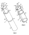
- the support anchor 1 shown in Figure 1 consists of a bolt 2, through which a Plastic part 3 is slipped over according to Figure 2.
- the plastic part 3 has several Sealing rings 5, the webs 9 and / or cuffs 5 at a distance are fixed to each other. The distance between the sealing rings 5 and / or Cuffs are adjustable.
- the plastic part 3 is provided with a channel 8.
- the injection hole 13a is aligned in the filling bore 13 of the support armature 1, as shown in FIG. 4.
- the End plate 4 is also with tabs 7 for the radial and axial alignment of the Support anchor provided.
- the mass is displaced by the bolt 2 and by the sealing ring 5th Fill out the defined rear anchoring area 23.
- the excess amount the mass 25 rises through the connecting channel 8 via the insulation area 19 in Direction of the mouth of the borehole and emerges from the opening 6 on the edge of the End plate 4 is arranged from.
- the connecting channel 8 is a longitudinal groove on the inside of the web 9 and the cuff 5 attached.
- the front anchoring area 22 arranged in the facing shell 18 is shown in FIG a separate process shown in FIG. 4.
- the curable mass 25 is through the arranged in the end plate 4 injection hole 13a, which in the filling bore 13 is aligned, injected.
- the injected mass 25 initially flows into the Deepest in the borehole, fills the anchoring area 22 delimited by the sealing ring 5 and rises towards the mouth of the borehole.
- the exit of the mass 25 through the openings 11 made in the lens 4 shows that the front Anchorage area 22 is filled.
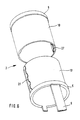
- the section shown in Figure 6 shows the plastic part 3, which consists of two Cuffs 5 exist which are connected together via a snap connection 27.
- This modified version of the support anchor enables, by moving the cuffs 5, a necessary adaptation of the plastic part 3 to the respective, renovating object.
Abstract
Description
Die Erfindung betrifft einen Traganker zur Befestigung einer Vorsatzschale an einer
Tragschale mit durch Dichtringe abgetrennten Verankerungsbereichen, die mit einer
aushärtbaren Masse auffüllbar sind, gemäß der Gattung des Anspruches 1.The invention relates to a support anchor for attaching a facing to a
Carrier shell with anchoring areas separated by sealing rings, which with a
curable mass are fillable, according to the preamble of
Aus der EP-A-0 351 668 ist ein gattungsgemäßer Traganker bekannt, der aus einem Stahlrohr besteht, das mit einem Abschnitt in der Tragschale und mit dem anderen Abschnitt in der Vorsatzschale mittels einer aushärtbaren Masse verankerbar ist. Die Verankerungsbereiche werden durch auf dem Stahlrohr aufgesetzte Kunststoffteile gebildet, an denen die Verankerungsbereiche abgrenzenden Dichtringe angeordnet sind. Die Befüllung beider Verankerungsbereiche erfolgt durch das Rohr in einem Befüllungsvorgang, wobei der Verankerungsbereich in der Tragschale durch Austritt der Masse aus dem vorderen Ende des Tragrohrs und die Befüllung des Verankerungsbereichs in der Vorsatzschale durch Austritt aus seitlichen Öffnungen im Rohr erfolgt. Da beide Verankerungsbereiche gleichzeitig befüllt werden, ist es weder möglich, für die Verankerung in der Trag- und Vorsatzschale unterschiedliche Verbundmassen zu verwenden, noch den Traganker zunächst nur in der Tragschale zu verankern, was beispielsweise bei Sanierungsprojekten durchaus zweckmäßig sein kann. Des weiteren zeigt die Druckschrift keine Möglichkeit auf, die vollständige Befüllung beider Verankerungsbereiche an der Außenfläche der Vorsatzschale zu kontrollieren.From EP-A-0 351 668 a generic anchor is known which consists of a Steel tube is there, with one section in the carrier shell and with the other section can be anchored in the facing by means of a hardenable mass. The anchoring areas are formed by plastic parts placed on the steel tube, on which the anchoring areas delimiting sealing rings are arranged. The Both anchoring areas are filled through the pipe in one filling process, where the anchoring area in the carrier shell by exiting the mass from the front end of the support tube and filling the anchoring area in the facing shell is made by exiting from side openings in the pipe. Because both anchoring areas to be filled at the same time, it is neither possible for anchoring to use different composite materials in the carrier and facing shell, yet initially anchor the support anchor only in the support shell, for example at Refurbishment projects can be useful. The document also shows no possibility of full filling of both anchoring areas check the outer surface of the facing.
Bei dem aus der DE-OS 25 56 493 und der FR-A-2 223 587 bekannten Traganker sind die im Abstand zueinander angeordneten und zur Begrenzung der Verankerungsbereiche dienenden Dichtringe in umlaufende Nuten des Tragankers eingelassen und dort fest positioniert. Damit sind bereits bei der Fertigung des Tragankers sowohl die Länge der Verankerungsbereiche als auch deren Positionierung auf dem Traganker unveränderbar festgelegt. Da sowohl die Wandungsdicken der Vorsatzschalen als auch die Abstände der Vorsatzschalen zur Tragschale je nach Anwendungsfall unterschiedlich sein können, ergeben sich für den bekannten Traganker Einschränkungen in seinem Anwendungsbereich. Die Anpassung des Tragankers an die bestehenden Verhältnisse eines Bauprojektes umfaßt den gesamten Traganker, da die Dichtringe herstellerseitig am Traganker angebracht und positioniert werden müssen. Damit erhöht sich der Fertigungs- und Dispositionsaufwand insbesondere bei Sanierungsprojekten.In the support anchor known from DE-OS 25 56 493 and FR-A-2 223 587 the spaced apart and to limit the anchoring areas serving sealing rings embedded in circumferential grooves of the support anchor and there firmly positioned. This means that the length is already included in the manufacture of the support anchor the anchoring areas and their positioning on the support anchor cannot be changed fixed. Since both the wall thicknesses of the facing shells and the The distances between the facing shells and the supporting shell vary depending on the application can be, there are restrictions in the known support anchor in his Scope of application. The adaptation of the anchor to the existing conditions A construction project includes the entire support anchor, since the sealing rings are manufactured by the manufacturer must be attached and positioned on the support anchor. This increases the manufacturing and scheduling expenses, especially for renovation projects.
Die EP-A-0 316 199 beschreibt ein Befestigungselement in Form einer Gewindestange, auf der zur Abdichtung der Verankerungsbereiche Scheiben mit Innengewinde durch Drehen axial verschiebbar und einzeln auf der Gewindestange positionierbar sind. Die Überbrückung des Abstands zwischen der Trag- und Vorsatzschale erfolgt über ein Kunststoffrohr, das in der Tragschale gleichzeitig auch die Abdichtung des Verankerungsbereiches übernimmt. Dazu ist eine Stufenbohrung in der Tragschale erforderlich, deren Durchmesser dem Außendurchmesser des Kunststoffrohres entspricht. Über ein Zuführrohr werden die einzelnen Verankerungsbereiche befüllt, wobei durch Verdrehen der Scheiben nach dem Zurückziehen des Zuführrohres die Verankerungsbereiche anschließend voneinander abgegrenzt werden. Allerdings zeigt auch diese Druckschrift keine Möglichkeit auf, die vollständige Befüllung beider Verankerungsbereiche zu kontrollieren. Lediglich die Befüllung des Verankerungsbereichs in der Tragschale ist durch Austritt der Masse aus einer Öffnung in der äußeren Abdichtscheibe kontrollierbar.EP-A-0 316 199 describes a fastening element in the form of a threaded rod, on the washers with an internal thread to seal the anchoring areas Rotate axially displaceable and can be individually positioned on the threaded rod. The The distance between the support and facing shell is bridged via a Plastic pipe that also seals the anchoring area in the carrier shell takes over. This requires a stepped hole in the carrier shell, whose diameter corresponds to the outer diameter of the plastic tube. About one Feed tube, the individual anchoring areas are filled, by twisting of the washers after pulling back the feed pipe, then the anchoring areas be differentiated from each other. However, this document also shows no possibility to check the complete filling of both anchoring areas. Only the filling of the anchoring area in the carrier shell is complete The mass can be controlled to escape from an opening in the outer sealing washer.
Der Erfindung liegt die Aufgabe zugrunde, einen montagefreundlichen und wirtschaftlich herstellbaren Traganker zur Befestigung einer Vorsatzschale an einer Tragschale zu schaffen, der durch einfache Anpassungsmöglichkeit an verschiedene Verhältnisse einen breiten Anwendungsbereich abdeckt und eine Befüllkontrolle beider Verankerungsbereiche ermöglicht. The invention is based, an assembly-friendly and economical task producible support anchor for fastening a facing shell to a support shell create the by easy adjustment to different conditions covers a wide range of applications and a filling check of both anchoring areas enables.
Die Lösung dieser Aufgabe wird durch die im Anspruch 1 angegebenen Merkmale erreicht.This object is achieved by the features specified in
Üblicherweise werden die Traganker zur Sicherung und Instandsetzung bereits montierter Fassadenkonstruktionen verwendet. Zur Montage des Tragankers wird durch die Vorsatzschale hindurch in die Tragschale ein Bohrloch erstellt, dessen Durchmesser dem Außendurchmesser der Dichtringe entspricht. In das Bohrloch der Tragschale wird eine aushärtbare Masse eingefüllt. Danach wird der Traganker mit dem übergestülpten Kunststoffteil soweit in das Bohrloch eingeführt, bis der erste Dichtring sich im Bohrloch der Tragschale befindet. Durch mehr oder weniger weites Einschieben des Kunststoffteiles wird sichergestellt, daß der ebenfalls durch Dichtringe begrenzte vordere Verankerungsbereich sich innerhalb der Bohrung in der Vorsatzschale befindet. Danach wird dieser Verankerungsbereich ebenfalls mit der aushärtbaren Masse ausgefüllt, so daß nach dem Aushärten der Masse eine spannungsfreie Verankerung in der Trag- und Vorsatzschale erreicht ist. Der Traganker nimmt somit die auf die Vorsatzschale wirkenden Schub- und Zugkräfte auf.Usually become the supporting anchors for securing and repairing already assembled facade constructions used. To mount the support anchor is through the facing shell a hole is drilled into the carrier shell, the diameter of which corresponds to the outside diameter corresponds to the sealing rings. A hardenable is drilled into the borehole of the carrier shell Mass filled. Then the support anchor with the slipped plastic part inserted into the borehole until the first sealing ring is in the borehole Carrier shell is located. By inserting the plastic part more or less it is ensured that the front anchoring area, which is also delimited by sealing rings is located in the hole in the facing. After that, this one Anchorage area also filled with the curable mass, so that after the hardening of the mass a tension-free anchoring in the carrier and facing shell is reached. The support anchor thus takes those acting on the facing shell Thrust and tensile forces.
Reicht,in einzelnen Fällen die Anpassungsmöglichkeit des Tragankers durch Verschieben im Bohrloch nicht aus, so ist es lediglich erforderlich, über den Traganker ein anderes Kunststoffteil überzustülpen, dessen Dichtringe über die Stege und/oder Manschetten in einem anderen Abstand zueinander fixiert sind.Enough, in individual cases, the possibility of adapting the support anchor by moving in the borehole, it is only necessary to put another plastic part over the support anchor, its sealing rings over the webs and / or cuffs are fixed at a different distance from one another.
In einer weiteren Ausgestaltung der Erfindung kann die Abstandsregulierung der Dichtringe auch über teleskopartig zusammenschieb- und verrastbare Stege und/oder Manschetten des Kunststoffteiles erfolgen. Damit können mit ein und demselben Kunststoffteil sowohl die Länge der Verankerungsbereiche als auch der Abstand zwischen den Verankerungsbereichen in Anpassung an die vorliegenden Dicken- und Abstandsverhältnisse der Vorsatz- und Tragschale verändert werden. In a further embodiment of the invention, the distance regulation of the sealing rings can also via telescopic collapsible and lockable bars and / or cuffs of the plastic part. So you can with the same plastic part both the length of the anchoring areas and the distance between the Anchoring areas to adapt to the existing thickness and spacing ratios the facing and support shell can be changed.
Der hintere in der Tragschale und der vordere in der Vorsatzschale gebildete Verankerungsbereich werden zweckmäßigerweise separat befüllt. Während die Befüllung des hinteren Verankerungsbereiches durch Aufsteigen der Masse vom Bohrlochgrund in Richtung Bohrlochmündung beim Einschieben des Tragankers in das mit der Masse teilweise befüllten Bohrloch erfolgt, wird zur Befüllung des vorderen Verankerungsbereiches die Masse durch eine Füllbohrung im vorderen Teil des Tragankers eingespritzt. Durch das getrennte und unterschiedliche Füllungsverfahren der beiden Verankerungsbereiche kann auf einen den Traganker vollständig durchquerenden und insbesondere in einem Edelstahl-Traganker schwer herstellbaren Füllkanal verzichtet werden. Durch den kürzeren, nur in den vorderen Verankerungsbereich mündenden Füllkanal kann eine Verbundmasse mit höherer Viskosität und damit kürzerer Aushärtzeit verwendet werden.The rear anchoring area formed in the carrier shell and the front one in the facing shell are expediently filled separately. While filling the rear anchoring area by ascending the mass from the bottom of the borehole Direction of the hole when inserting the support anchor into the mass partially filled borehole is used to fill the front anchoring area the mass is injected through a filling hole in the front part of the anchor. Due to the separate and different filling process of the two anchoring areas can on a completely crossing the anchor and in particular filling channel that is difficult to manufacture in a stainless steel support anchor. By the shorter filling channel, which only opens into the front anchoring area a compound with a higher viscosity and therefore shorter curing time become.
Zur Befüllungskontrolle des hinteren Verankerungsbereiches ist es zweckmäßig, am Traganker einen vom hinteren Verankerungsbereich ausgehenden und bis zur Stirnseite des Tragankers geführten Verbindungskanal anzuordnen. Zweckmäßigerweise ist der Verbindungskanal als Längsnut entlang der Innenseite eines Steges und der Manschette angeordnet.To check the filling of the rear anchoring area, it is advisable to Anchor from the rear anchoring area and up to To arrange the end face of the support anchor guided connection channel. The connecting channel is expediently designed as a longitudinal groove along the inside a web and the cuff arranged.
Als Füllkontrolle sind im Randbereich der Abschlußscheibe Öffnungen angeordnet, die mit den Verankerungsbereichen verbunden sind. Ferner weist die Abschlußscheibe eine axial abstehende Grifflasche auf, mit der das Kunststoffteil auf dem Traganker verdreht und ausgerichtet werden kann.As a filling control there are openings in the edge area of the lens arranged, which are connected to the anchoring areas. Furthermore points the lens has an axially projecting grip tab with which the plastic part can be rotated and aligned on the support anchor.
In der Zeichnung sind Ausführungsbeispiele der Erfindung dargestellt.
Figur 1- den erfindungsgemäßen Traganker in Sicht
Figur 2- das Kunststoffteil in Sicht
Figur 3- den gesetzten Traganker mit befülltem, hinteren Verankerungsbereich
- Figur 4
- den gesetzten Traganker gemäß
Figur 1 während der Befüllung des vorderen Verankerungsbereiches Figur 5- eine abgewandelte Ausführung des Tragankers
Figur 6- das Kunststoffteil gemäß
Figur 2 mit einer Rastverbindung
- Figure 1
- the support anchor according to the invention in sight
- Figure 2
- the plastic part in sight
- Figure 3
- the set anchor with filled, rear anchoring area
- Figure 4
- the set anchor according to Figure 1 during the filling of the front anchoring area
- Figure 5
- a modified version of the support anchor
- Figure 6
- the plastic part according to Figure 2 with a snap connection
Der in Figur 1 dargestellte Traganker 1 besteht aus einem Bolzen 2, über den ein
Kunststoffteil 3 gemäß Figur 2 übergestülpt ist. Der Kunststoffteil 3 weist mehrere
Dichtringe 5, die über die Stege 9 und/oder Manschetten 5 in einem Abstand
zueinander fixiert sind, auf. Der Abstand zwischen den Dichtringen 5 und/oder
Manschetten ist verstellbar. Ferner ist der Kunststoffteil 3 mit einem Kanal 8 versehen.
An der Stirnseite des Tragankers 1 befindet sich eine Abschlußscheibe 4, die mit einer
Injektionsbohrung 13a und Öffnungen 6, 11 versehen ist. Die Injektionsbohrung 13a
fluchtet in die Füllbohrung 13 des Tragankers 1, wie die Figur 4 darstellt. Die
Abschlußscheibe 4 ist auch mit Grifflaschen 7 für das radiale und axiale Ausrichten des
Tragankers versehen. Nach dem Einführen des Tragankers 1 in das mit der
aushärtbaren Masse 25 befüllte Bohrloch 24 in der Tragschale 17, wie die Figur 3
darstellt, wird die Masse durch den Bolzen 2 verdrängt und den durch den Dichtring 5
abgegrenzten hinteren Verankerungsbereich 23 ausfüllen. Die überschüssige Menge
der Masse 25 steigt durch den Verbindungskanal 8 über den Dämmbereich 19 in
Richtung der Bohrlochmündung und tritt aus der Öffnung 6, die am Rande der
Abschlußscheibe 4 angeordnet ist, aus. Durch den Austritt der Masse erhält der
Monteur die Sicherheit, daß der hintere Verankerungsbereich 23 vollständig ausgefüllt
worden ist. Der Verbindungskanal 8 ist als Längsnut an der Innenseite des Steges 9
und der Manschette 5 angebracht.The
Der vordere in der Vorsatzschale 18 angeordnete Verankerungsbereich 22 wird in
einem separaten, in der Figur 4 dargestellten Vorgang befüllt. Die aushärtbare Masse
25 wird durch die in der Abschlußscheibe 4 angeordnete Injektionsbohrung 13a, die in
der Füllbohrung 13 fluchtet, eingespritzt. Die eingespritzte Masse 25 fließt zunächst ins
Bohrlochtiefste, füllt den durch den Dichtring 5 abgegrenzten Verankerungsbereich 22
aus und steigt in Richtung der Bohrlochmündung auf. Der Austritt der Masse 25 durch
die in der Abschlußscheibe 4 angebrachten Öffnungen 11 zeigt, daß der vordere
Verankerungsbereich 22 ausgefüllt ist.The
In der Figur 5 ist die Befüllung des hinteren Verankerungsbereiches 23 des Tragsankers
1 dargestellt, wobei der Verbindungskanal 8 als Längsnut auf der Mantelfläche des
Tragankers 1 angebracht ist.5 is the filling of the
Der in der Figur 6 dargestellte Ausschnitt zeigt das Kunststoffteil 3, das aus zwei
Manschetten 5 besteht, die über eine Rastverbindung 27 zusammen verbunden sind.
Diese abgewandelte Ausführung des Tragankers ermöglicht, durch die Verschiebung
der Manschetten 5, eine erforderliche Anpassung des Kunststoffteils 3 dem jeweiligen,
sanierenden Objekt.The section shown in Figure 6 shows the
Claims (5)
- Support anchor for fastening a supplementary shell (18) to a support shell (17), having anchoring regions (22, 23) separated by sealing rings (5), which anchoring regions can be filled with a curable compound, the sealing rings (5) being arranged on a plastics member (3) that is placed over the support anchor (1) and being fixed at a distance from one another by means of ribs (9) and/or sleeves (10), characterised in that the plastics member (3) has a closure disc (4) that rests on the end face of the support anchor (1) and has an injection bore (13a) which is in alignment with a filling bore (13) in the support anchor (1) that opens into the forward anchoring region (22), and the closure disc (4) has openings (6, 11) in its peripheral region, one of the openings (6) being connected to the rear anchoring region (23) and the other opening (11) being connected to the forward anchoring region (22).
- Support anchor according to claim 1, characterised in that the spacing between the sealing rings can be adjusted by means of ribs (9) and/or sleeves (10) that can be pushed together telescopically and locked in place.
- Support anchor according to claim 1, characterised in that there is arranged on the support anchor (1) a connecting channel (8) that starts from the rear anchoring region (23) and continues as far as the end face of the support anchor (1).
- Support anchor according to claim 3, characterised in that the connecting channel (8) is in the form of a longitudinal groove which extends along the inner side of the rib (9) and the sleeve (10).
- Support anchor according to claim 1, characterised in that the closure disc (4) is provided with an axially projecting grip tab (7).
Applications Claiming Priority (2)
| Application Number | Priority Date | Filing Date | Title |
|---|---|---|---|
| DE19546844A DE19546844A1 (en) | 1995-12-15 | 1995-12-15 | Support anchor for fastening a facing shell to a supporting shell |
| DE19546844 | 1995-12-15 |
Publications (2)
| Publication Number | Publication Date |
|---|---|
| EP0779438A1 EP0779438A1 (en) | 1997-06-18 |
| EP0779438B1 true EP0779438B1 (en) | 2001-06-13 |
Family
ID=7780207
Family Applications (1)
| Application Number | Title | Priority Date | Filing Date |
|---|---|---|---|
| EP96117900A Expired - Lifetime EP0779438B1 (en) | 1995-12-15 | 1996-11-08 | Supporting anchor for fastening an outer shell wall to a supporting shell wall |
Country Status (17)
| Country | Link |
|---|---|
| EP (1) | EP0779438B1 (en) |
| KR (1) | KR100220983B1 (en) |
| CN (1) | CN1158377A (en) |
| AT (1) | ATE202187T1 (en) |
| CZ (1) | CZ291845B6 (en) |
| DE (2) | DE19546844A1 (en) |
| DK (1) | DK0779438T3 (en) |
| ES (1) | ES2159672T3 (en) |
| FI (1) | FI965001A (en) |
| HR (1) | HRP960591A2 (en) |
| HU (1) | HUP9603343A3 (en) |
| NO (1) | NO965390L (en) |
| PL (1) | PL182120B1 (en) |
| RU (1) | RU2146748C1 (en) |
| SI (1) | SI9600366A (en) |
| SK (1) | SK283443B6 (en) |
| YU (1) | YU65996A (en) |
Families Citing this family (3)
| Publication number | Priority date | Publication date | Assignee | Title |
|---|---|---|---|---|
| DE10043848B4 (en) * | 2000-09-06 | 2005-02-10 | Thumm, Günther | Mounting sleeve for a wall anchor |
| DE102013101505A1 (en) | 2013-02-15 | 2014-08-21 | Fischerwerke Gmbh & Co. Kg | Ground anchor for mounting facing shell at carrying shell in mounting arrangement during reconstruction of buildings, has outlet port provided on rear surface of sealing rings, and centering element arranged in front end of bolt |
| CN110513373B (en) * | 2019-07-02 | 2024-03-15 | 青岛海尔洗衣机有限公司 | Washing equipment installation assembly, installation method and wall-mounted washing equipment |
Family Cites Families (10)
| Publication number | Priority date | Publication date | Assignee | Title |
|---|---|---|---|---|
| DE7311989U (en) * | 1900-01-01 | Harke, Alfons, 5600 Wuppertal, De | ||
| DE2315859C2 (en) * | 1973-03-30 | 1985-03-07 | International Intec Co. Ets., Vaduz | Anchor bolts |
| DE2556493A1 (en) | 1975-12-16 | 1977-06-30 | Alfons Harke | Adhesively fixed wall anchor bolt - uses helical web to influence adhesive flow behind outer sealing ring |
| DE2739146C2 (en) * | 1977-08-31 | 1985-01-24 | Günter 4930 Detmold Joly | Hollow injection dowel |
| DE3322198A1 (en) * | 1983-06-21 | 1985-01-17 | Günter 4930 Detmold Joly | Method for fixing a hollow dowel |
| GB8323140D0 (en) * | 1983-08-27 | 1983-09-28 | Hilti Ag | Constructional tie |
| DE3873486T2 (en) * | 1987-11-12 | 1992-12-03 | David Patrick Payne | METHOD AND MEANS FOR CONNECTING COMPONENTS. |
| DE3805538A1 (en) * | 1988-02-23 | 1989-08-31 | Int Intec Co Ets | INJECTION ANCHOR TO BE INSERTED INTO PRE-DRILLED HOLES OF A MULTI-SHELLED BUILDING WALL |
| DE3840055C2 (en) * | 1988-07-15 | 1994-03-17 | Maechtle Gmbh | Facade dowels |
| EP0351668B1 (en) * | 1988-07-15 | 1992-10-14 | Mächtle GmbH | Dowel for façades |
-
1995
- 1995-12-15 DE DE19546844A patent/DE19546844A1/en not_active Withdrawn
-
1996
- 1996-11-08 ES ES96117900T patent/ES2159672T3/en not_active Expired - Lifetime
- 1996-11-08 EP EP96117900A patent/EP0779438B1/en not_active Expired - Lifetime
- 1996-11-08 DE DE59607079T patent/DE59607079D1/en not_active Expired - Lifetime
- 1996-11-08 AT AT96117900T patent/ATE202187T1/en not_active IP Right Cessation
- 1996-11-08 DK DK96117900T patent/DK0779438T3/en active
- 1996-11-15 CZ CZ19963376A patent/CZ291845B6/en not_active IP Right Cessation
- 1996-11-28 SK SK1526-96A patent/SK283443B6/en unknown
- 1996-12-04 HU HU9603343A patent/HUP9603343A3/en unknown
- 1996-12-10 PL PL96317413A patent/PL182120B1/en not_active IP Right Cessation
- 1996-12-11 YU YU65996A patent/YU65996A/en unknown
- 1996-12-11 RU RU96123409A patent/RU2146748C1/en active
- 1996-12-13 NO NO965390A patent/NO965390L/en not_active Application Discontinuation
- 1996-12-13 KR KR1019960064971A patent/KR100220983B1/en not_active IP Right Cessation
- 1996-12-13 SI SI9600366A patent/SI9600366A/en unknown
- 1996-12-13 HR HR19546844.9A patent/HRP960591A2/en not_active Application Discontinuation
- 1996-12-13 FI FI965001A patent/FI965001A/en unknown
- 1996-12-14 CN CN96121332A patent/CN1158377A/en active Pending
Also Published As
| Publication number | Publication date |
|---|---|
| NO965390D0 (en) | 1996-12-13 |
| HUP9603343A2 (en) | 1999-04-28 |
| CZ9603376A3 (en) | 2001-02-14 |
| RU2146748C1 (en) | 2000-03-20 |
| PL182120B1 (en) | 2001-11-30 |
| ATE202187T1 (en) | 2001-06-15 |
| ES2159672T3 (en) | 2001-10-16 |
| SI9600366A (en) | 1997-08-31 |
| KR100220983B1 (en) | 1999-09-15 |
| SK152696A3 (en) | 1998-01-14 |
| DE59607079D1 (en) | 2001-07-19 |
| YU65996A (en) | 1999-06-15 |
| FI965001A (en) | 1997-06-16 |
| FI965001A0 (en) | 1996-12-13 |
| NO965390L (en) | 1997-06-16 |
| PL317413A1 (en) | 1997-06-23 |
| SK283443B6 (en) | 2003-07-01 |
| DK0779438T3 (en) | 2001-07-16 |
| KR970045755A (en) | 1997-07-26 |
| HUP9603343A3 (en) | 1999-05-28 |
| DE19546844A1 (en) | 1997-06-19 |
| CN1158377A (en) | 1997-09-03 |
| CZ291845B6 (en) | 2003-06-18 |
| HRP960591A2 (en) | 1997-08-31 |
| EP0779438A1 (en) | 1997-06-18 |
| HU9603343D0 (en) | 1997-01-28 |
Similar Documents
| Publication | Publication Date | Title |
|---|---|---|
| EP0150668A1 (en) | Expanding dovel | |
| DE3335628C2 (en) | ||
| DE3229470C2 (en) | Tunnel lining segment with locking elements | |
| EP2158406A2 (en) | Mounting fixture for a light building board | |
| DE3812913A1 (en) | DUEBEL WITH SEVENTHAL SLEEVE | |
| DE19840521C1 (en) | Fastener for insulation panel has a two part sleeve which provides an aligned grip for different thicknesses of panel and which is secured to the base by fittings | |
| AT395893B (en) | FASTENING DEVICE FOR CONNECTING COMPONENTS | |
| DE4413743A1 (en) | Fastening anchor | |
| WO2015028680A1 (en) | Connecting insert and an embedding method and a production method therefor | |
| WO2005124163A1 (en) | Injection fixing arrangement and injection fixing method | |
| DE2838466A1 (en) | Adhesively fixed wall plug - has bush fitted with clearance in blind bore and secured by injecting setting agent | |
| EP0779438B1 (en) | Supporting anchor for fastening an outer shell wall to a supporting shell wall | |
| DE2723729C2 (en) | Anchoring a fastening element in a borehole of a masonry having cavities | |
| EP0021454A1 (en) | Tensioning ring for fixing a resilient sealing ring in a socket | |
| EP1366303A1 (en) | Fixing element for insulation material | |
| EP1179649B1 (en) | Injection fastening anchor | |
| DE3445520A1 (en) | PLASTIC SPREADING DOWEL | |
| EP1333184A2 (en) | Expansion anchor | |
| WO2003083316A1 (en) | Bonding anchor | |
| DE10216897A1 (en) | Bonding anchor for anchoring in a borehole using mortar comprises an anchor rod with a front end provided with an expanding region formed by an expanding sleeve and an expanding body and having a longitudinal mortar channel | |
| DE102004020118A1 (en) | Anchor for fixing a plate-like outer shell to a brick wall in the lining of houses comprises a longitudinal hollow body for inserting an injection composition via a filling opening | |
| DE19639604A1 (en) | Composite dowels | |
| DE10043848B4 (en) | Mounting sleeve for a wall anchor | |
| EP3135861A1 (en) | Attachment device | |
| DE4016956C1 (en) | Height-adjustable support feet - are used on bath or shower unit and have telescopic tubes with clamping arrangement |
Legal Events
| Date | Code | Title | Description |
|---|---|---|---|
| PUAI | Public reference made under article 153(3) epc to a published international application that has entered the european phase |
Free format text: ORIGINAL CODE: 0009012 |
|
| AK | Designated contracting states |
Kind code of ref document: A1 Designated state(s): AT BE CH DE DK ES FR GB GR IE IT LI NL PT SE |
|
| 17P | Request for examination filed |
Effective date: 19970516 |
|
| 17Q | First examination report despatched |
Effective date: 19990329 |
|
| GRAG | Despatch of communication of intention to grant |
Free format text: ORIGINAL CODE: EPIDOS AGRA |
|
| GRAG | Despatch of communication of intention to grant |
Free format text: ORIGINAL CODE: EPIDOS AGRA |
|
| GRAH | Despatch of communication of intention to grant a patent |
Free format text: ORIGINAL CODE: EPIDOS IGRA |
|
| GRAH | Despatch of communication of intention to grant a patent |
Free format text: ORIGINAL CODE: EPIDOS IGRA |
|
| GRAA | (expected) grant |
Free format text: ORIGINAL CODE: 0009210 |
|
| AK | Designated contracting states |
Kind code of ref document: B1 Designated state(s): AT BE CH DE DK ES FR GB GR IE IT LI NL PT SE |
|
| PG25 | Lapsed in a contracting state [announced via postgrant information from national office to epo] |
Ref country code: IE Free format text: LAPSE BECAUSE OF FAILURE TO SUBMIT A TRANSLATION OF THE DESCRIPTION OR TO PAY THE FEE WITHIN THE PRESCRIBED TIME-LIMIT Effective date: 20010613 |
|
| REF | Corresponds to: |
Ref document number: 202187 Country of ref document: AT Date of ref document: 20010615 Kind code of ref document: T |
|
| REG | Reference to a national code |
Ref country code: CH Ref legal event code: NV Representative=s name: PATENTANWAELTE SCHAAD, BALASS, MENZL & PARTNER AG |
|
| GBT | Gb: translation of ep patent filed (gb section 77(6)(a)/1977) |
Effective date: 20010613 |
|
| REG | Reference to a national code |
Ref country code: DK Ref legal event code: T3 |
|
| REF | Corresponds to: |
Ref document number: 59607079 Country of ref document: DE Date of ref document: 20010719 |
|
| REG | Reference to a national code |
Ref country code: IE Ref legal event code: FG4D Free format text: GERMAN |
|
| ITF | It: translation for a ep patent filed |
Owner name: ING. ZINI MARANESI & C. S.R.L. |
|
| PG25 | Lapsed in a contracting state [announced via postgrant information from national office to epo] |
Ref country code: SE Free format text: LAPSE BECAUSE OF FAILURE TO SUBMIT A TRANSLATION OF THE DESCRIPTION OR TO PAY THE FEE WITHIN THE PRESCRIBED TIME-LIMIT Effective date: 20010913 |
|
| PG25 | Lapsed in a contracting state [announced via postgrant information from national office to epo] |
Ref country code: GR Free format text: LAPSE BECAUSE OF FAILURE TO SUBMIT A TRANSLATION OF THE DESCRIPTION OR TO PAY THE FEE WITHIN THE PRESCRIBED TIME-LIMIT Effective date: 20010914 |
|
| PG25 | Lapsed in a contracting state [announced via postgrant information from national office to epo] |
Ref country code: PT Free format text: LAPSE BECAUSE OF FAILURE TO SUBMIT A TRANSLATION OF THE DESCRIPTION OR TO PAY THE FEE WITHIN THE PRESCRIBED TIME-LIMIT Effective date: 20010917 |
|
| REG | Reference to a national code |
Ref country code: ES Ref legal event code: FG2A Ref document number: 2159672 Country of ref document: ES Kind code of ref document: T3 |
|
| PG25 | Lapsed in a contracting state [announced via postgrant information from national office to epo] |
Ref country code: DK Free format text: LAPSE BECAUSE OF NON-PAYMENT OF DUE FEES Effective date: 20011108 |
|
| PG25 | Lapsed in a contracting state [announced via postgrant information from national office to epo] |
Ref country code: ES Free format text: LAPSE BECAUSE OF NON-PAYMENT OF DUE FEES Effective date: 20011109 |
|
| ET | Fr: translation filed | ||
| PG25 | Lapsed in a contracting state [announced via postgrant information from national office to epo] |
Ref country code: BE Free format text: LAPSE BECAUSE OF NON-PAYMENT OF DUE FEES Effective date: 20011130 |
|
| REG | Reference to a national code |
Ref country code: GB Ref legal event code: IF02 |
|
| PLBE | No opposition filed within time limit |
Free format text: ORIGINAL CODE: 0009261 |
|
| STAA | Information on the status of an ep patent application or granted ep patent |
Free format text: STATUS: NO OPPOSITION FILED WITHIN TIME LIMIT |
|
| BERE | Be: lapsed |
Owner name: UPAT G.M.B.H. & CO. Effective date: 20011130 |
|
| PG25 | Lapsed in a contracting state [announced via postgrant information from national office to epo] |
Ref country code: NL Free format text: LAPSE BECAUSE OF NON-PAYMENT OF DUE FEES Effective date: 20020601 |
|
| 26N | No opposition filed | ||
| REG | Reference to a national code |
Ref country code: DK Ref legal event code: EBP |
|
| NLV4 | Nl: lapsed or anulled due to non-payment of the annual fee |
Effective date: 20020601 |
|
| REG | Reference to a national code |
Ref country code: ES Ref legal event code: FD2A Effective date: 20021213 |
|
| PGFP | Annual fee paid to national office [announced via postgrant information from national office to epo] |
Ref country code: GB Payment date: 20041104 Year of fee payment: 9 |
|
| PGFP | Annual fee paid to national office [announced via postgrant information from national office to epo] |
Ref country code: FR Payment date: 20041109 Year of fee payment: 9 |
|
| PGFP | Annual fee paid to national office [announced via postgrant information from national office to epo] |
Ref country code: AT Payment date: 20041111 Year of fee payment: 9 |
|
| PGFP | Annual fee paid to national office [announced via postgrant information from national office to epo] |
Ref country code: CH Payment date: 20041117 Year of fee payment: 9 |
|
| PG25 | Lapsed in a contracting state [announced via postgrant information from national office to epo] |
Ref country code: IT Free format text: LAPSE BECAUSE OF NON-PAYMENT OF DUE FEES Effective date: 20051108 Ref country code: GB Free format text: LAPSE BECAUSE OF NON-PAYMENT OF DUE FEES Effective date: 20051108 Ref country code: AT Free format text: LAPSE BECAUSE OF NON-PAYMENT OF DUE FEES Effective date: 20051108 |
|
| PG25 | Lapsed in a contracting state [announced via postgrant information from national office to epo] |
Ref country code: LI Free format text: LAPSE BECAUSE OF NON-PAYMENT OF DUE FEES Effective date: 20051130 Ref country code: CH Free format text: LAPSE BECAUSE OF NON-PAYMENT OF DUE FEES Effective date: 20051130 |
|
| REG | Reference to a national code |
Ref country code: CH Ref legal event code: PL |
|
| GBPC | Gb: european patent ceased through non-payment of renewal fee |
Effective date: 20051108 |
|
| PG25 | Lapsed in a contracting state [announced via postgrant information from national office to epo] |
Ref country code: FR Free format text: LAPSE BECAUSE OF NON-PAYMENT OF DUE FEES Effective date: 20060731 |
|
| REG | Reference to a national code |
Ref country code: FR Ref legal event code: ST Effective date: 20060731 |
|
| PGFP | Annual fee paid to national office [announced via postgrant information from national office to epo] |
Ref country code: DE Payment date: 20120917 Year of fee payment: 17 |
|
| REG | Reference to a national code |
Ref country code: DE Ref legal event code: R119 Ref document number: 59607079 Country of ref document: DE Effective date: 20140603 |
|
| PG25 | Lapsed in a contracting state [announced via postgrant information from national office to epo] |
Ref country code: DE Free format text: LAPSE BECAUSE OF NON-PAYMENT OF DUE FEES Effective date: 20140603 |