EP0779237A2 - Mobile crane with an overload protection device - Google Patents
Mobile crane with an overload protection device Download PDFInfo
- Publication number
- EP0779237A2 EP0779237A2 EP96118130A EP96118130A EP0779237A2 EP 0779237 A2 EP0779237 A2 EP 0779237A2 EP 96118130 A EP96118130 A EP 96118130A EP 96118130 A EP96118130 A EP 96118130A EP 0779237 A2 EP0779237 A2 EP 0779237A2
- Authority
- EP
- European Patent Office
- Prior art keywords
- boom
- rotation
- sliding
- angle
- overload protection
- Prior art date
- Legal status (The legal status is an assumption and is not a legal conclusion. Google has not performed a legal analysis and makes no representation as to the accuracy of the status listed.)
- Granted
Links
Images
Classifications
-
- B—PERFORMING OPERATIONS; TRANSPORTING
- B66—HOISTING; LIFTING; HAULING
- B66C—CRANES; LOAD-ENGAGING ELEMENTS OR DEVICES FOR CRANES, CAPSTANS, WINCHES, OR TACKLES
- B66C23/00—Cranes comprising essentially a beam, boom, or triangular structure acting as a cantilever and mounted for translatory of swinging movements in vertical or horizontal planes or a combination of such movements, e.g. jib-cranes, derricks, tower cranes
- B66C23/88—Safety gear
- B66C23/90—Devices for indicating or limiting lifting moment
Definitions
- the invention relates to a crane vehicle with an overload protection device, with a boom articulated on its superstructure, preferably a telescopic boom, which can be rocked by a rocker cylinder articulated on this and the superstructure, with extendable sliding spars arranged on the opposite end regions of the long sides of the undercarriage Ends are provided with extendable support feet, and with a device measuring the angle of rotation of the boom, the signals of which are fed to a processing device of the overload protection device, in which the overload protection device generates a warning signal and / or stops the crane operation when the crane approaches or exceeds its stability-threatening limits .
- the stability of a crane vehicle with a telescopic boom depends not only on the size of the load hanging on the telescopic boom, but also on the luffing angle, the extension length of the telescopic boom, the deflection of the telescopic boom and in particular also on the angle of rotation of the uppercarriage with the telescopic boom to the undercarriage and the support legs of the sliding beams defined stand square.
- the safety of the crane is greatest when the boom points in the direction of the most extended sliding beam.
- Sliding bars with extended support feet ensure greater stability in the longitudinal direction of the undercarriage than in the direction of its transverse axis.
- the overload safety device must therefore always take into account the extended state of the sliding struts, which is problematic in that the stability changes even with different extending lengths of the individual sliding struts.
- the object of the invention is therefore to create a crane vehicle of the type specified at the outset, in which the overload protection device reliably takes into account the different extension lengths of the sliding struts.
- this object is achieved in a crane vehicle of the type specified at the outset in that a monitoring device is provided which detects the extension state or the extension length of the sliding spars, which supplies the signals of the overload protection device corresponding to the respective extension length of the individual sliding spars, and that the processing device of the overload protection device from the Signals of the monitoring device for the extension length of the sliding spars and from the signals of the device measuring the angle of rotation of the boom for each angle of rotation of the boom determine the stability of the standing square resulting from the extended state of the sliding spars.
- the signals generated by the angle of rotation measuring device and the monitoring device of the sliding spars in accordance with the angle of rotation or the extension lengths of the sliding spars are processed by the processing device, which contains a microcomputer, by comparison with the other values determining the stability, the overload protection device generating a signal stopping the crane operation when the crane approaches or exceeds its stability-threatening limits.
- the 360 ° rotation angle of the boom is divided into a plurality of rotation angle ranges and that for each of these rotation angle ranges, the booms located in this area result from the extension lengths of the Stability safety values resulting in sliding beams are stored in a table (bit map), from which the processing unit reads the current stability values of the standing square in accordance with the measured extension lengths of the sliding beams.
- each sliding beam has only three support positions in which it is bolted, namely once a retracted position in which the support foot is located in the area of the longitudinal side of the undercarriage, a middle position and a fully extended position . If only these three support positions are taken into account when calculating the stability for each of the four sliding spars, the safety values for each of the areas can be stored in a clear table.
- the computing work of the processing device can be reduced even further by dividing the 360 ° angle of rotation of the boom into four quadrants for determining the stability values of the standing rectangle. For each of these four quadrants, the stability values for all possible extension lengths of the sliding beams are stored in such a way that the smallest values valid for them are valid for the entire quadrant.
- the angular ranges lying in the safety range are determined from the measured values of the angle of rotation of the boom and the extension lengths of the sliding beams which the boom can be rotated at a predetermined load to a predetermined smallest luffing angle of the boom.
- variable angular ranges are defined in which the boom can be rotated safely with the load attached to it. For each of these angular ranges, the smallest rocking angle that is permissible in this angular range is assumed. This definition of variable angular ranges also simplifies the calculation since the permissible safety values do not have to be taken into account for every angle of the jib.
- the reduction in the angular ranges has the advantage that the crane operator does not have to fear in larger angular ranges to approach an angular limit at which the overload safety device responds.
- the choice of larger angular ranges means that the higher loads that are permissible in certain areas, for example by pivoting the boom to smaller luffing angles, cannot be used in these.
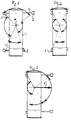
- FIG. 1 schematically shows an undercarriage 1 of a crane vehicle, from which the sliding spars 2 are extended to different extents, which support legs 3 at their ends, which can be extended vertically against the ground by hydraulic cylinders at right angles to the sliding spars. Threaded spindles can also be provided to extend the support feet.
- the sliding beams 2 are located in the end regions of the two long sides of the undercarriage 1 and can be extended at right angles to its longitudinal center plane.
- the sliding beams can be extended in three stages, in which they must each be bolted in their guides. These steps correspond to a retracted position in which the support lengths of the sliding spars are smallest, an intermediate position and an extended position in which the support length is greatest.
- the two sliding beams 2 on the left side are in their middle position, the upper sliding beam on the right side in its most extended position and the sliding beam on the lower right in its retracted position Position.
- This extension pattern of the sliding spars and the resulting support lengths result in a standing square, which is able to take up different rocking forces over the angle of rotation of the boom.
- angular ranges have been defined in the standing square, which result from the lines drawn from the axis of rotation 4 of the boom to the ends of the sliding spars 2 or through the support lines of the support feet 3.
- certain permissible cantilever moments have been defined, the different sizes of which are indicated by the radius of the circular arc spanning the angular ranges.
- a uniform permissible cantilever torque is defined for each angular range, which corresponds to the largest permissible cantilever torque for this angular range.
- the different four-angle ranges resulting from the different extension lengths of the sliding beams as well as the largest cantilever moments permitted for each of these angle ranges are stored in a payload table from which these values can be read out for processing in the processing unit with the overload protection device.
Landscapes
- Engineering & Computer Science (AREA)
- Mechanical Engineering (AREA)
- Jib Cranes (AREA)
Abstract
Description
Die Erfindung betrifft ein Kranfahrzeug mit einer Überlastsicherungseinrichtung, mit einem an dessen Oberwagen angelenkten Ausleger, vorzugsweise Teleskopausleger, der durch einen an diesem und dem Oberwagen angelenkten Wippzylinder wippbar ist, mit an den einander gegenüberliegenden Endbereichen der Längsseiten des Unterwagens angeordneten ausfahrbaren Schiebeholmen, die an ihren Enden mit ausfahrbaren Stützfüßen versehen sind, und mit einer den Drehwinkel des Auslegers messenden Einrichtung, deren Signale einer Verarbeitungseinrichtung der Überlastsicherungseinrichtung zugeführt werden, bei dem die Überlastsicherungseinrichtung ein Warnsignal erzeugt und/oder den Kranbetrieb stoppt, wenn der Kran seine Standsicherheit gefährdenden Grenzen anfährt oder überschreitet.The invention relates to a crane vehicle with an overload protection device, with a boom articulated on its superstructure, preferably a telescopic boom, which can be rocked by a rocker cylinder articulated on this and the superstructure, with extendable sliding spars arranged on the opposite end regions of the long sides of the undercarriage Ends are provided with extendable support feet, and with a device measuring the angle of rotation of the boom, the signals of which are fed to a processing device of the overload protection device, in which the overload protection device generates a warning signal and / or stops the crane operation when the crane approaches or exceeds its stability-threatening limits .
Die Standsicherheit eines Kranfahrzeugs mit Teleskopausleger hängt neben der Größe der an dem Teleskopausleger hängenden Last unter anderem von dem Wippwinkel, der Ausfahrlänge des Teleskopauslegers, von der Durchbiegung des Teleskopauslegers und insbesondere auch von dem Drehwinkel des Oberwagens mit Teleskopausleger zu dem Unterwagen und dem durch die Stützfüße der Schiebeholme definierten Stand-Viereck ab. Bezogen auf das durch die ausgefahrenen Schiebeholme und Stützfüße definierte Stand-Viereck ist die Sicherheit des Krans am größten, wenn der Ausleger in Richtung des am weitesten ausgefahrenen Schiebeholms weist. Bei eingefahrenen Schiebeholmen mit ausgefahrenen Stützfüßen ist die Standsicherheit in Längsrichtung des Unterwagens größer als in Richtung zu dessen Querachse. Die Überlastsicherung muß daher immer auch den Ausfahrzustand der Schiebeholme berücksichtigen, was insofern problematisch ist, als sich die Standsicherheit auch bei unterschiedlicher Ausfahrlänge der einzelnen Schiebeholme ändert.The stability of a crane vehicle with a telescopic boom depends not only on the size of the load hanging on the telescopic boom, but also on the luffing angle, the extension length of the telescopic boom, the deflection of the telescopic boom and in particular also on the angle of rotation of the uppercarriage with the telescopic boom to the undercarriage and the support legs of the sliding beams defined stand square. Relative to the quadrilateral defined by the extended sliding beams and support feet, the safety of the crane is greatest when the boom points in the direction of the most extended sliding beam. When retracted Sliding bars with extended support feet ensure greater stability in the longitudinal direction of the undercarriage than in the direction of its transverse axis. The overload safety device must therefore always take into account the extended state of the sliding struts, which is problematic in that the stability changes even with different extending lengths of the individual sliding struts.
Aufgabe der Erfindung ist es daher, ein Kranfahrzeug der eingangs angegebenen Art zu schaffen, bei dem die Überlastsicherungseinrichtung in zuverlässiger Weise die unterschiedlichen Ausfahrlängen der Schiebeholme berücksichtigt.The object of the invention is therefore to create a crane vehicle of the type specified at the outset, in which the overload protection device reliably takes into account the different extension lengths of the sliding struts.
Erfindungsgemäß wird diese Aufgabe bei einen Kranfahrzeug der eingangs angegebenen Art dadurch gelöst, daß eine den Ausfahrzustand bzw. die Ausfahrlänge der Schiebeholme erfassende Überwachungseinrichtung vorgesehen ist, die der jeweiligen Ausfahrlänge der einzelnen Schiebeholme entsprechende Signale der Überlastsicherungseinrichtung zuführt, und daß die Verarbeitungseinrichtung der Überlastsicherungseinrichtung aus den Signalen der Überwachungseinrichtung für die Ausfahrlänge der Schiebeholme und aus den Signalen der den Drehwinkel des Auslegers messenden Einrichtung für jeden Drehwinkel des Auslegers die sich aus dem Ausfahrzustand der Schiebeholme ergebende Standsicherheit des Stand-Vierecks ermittelt. Die von der Drehwinkelmeßeinrichtung und der Überwachungseinrichtung der Schiebeholme entsprechend dem Drehwinkel bzw. den Ausfahrlängen der Schiebeholme erzeugten Signale werden von der Verarbeitungseinrichtung, die einen Mikrocomputer enthält, durch Vergleich mit den weiteren die Standsicherheit bestimmenden Werten verarbeitet, wobei die Überlastsicherungseinrichtung ein den Kranbetrieb stoppendes Signal erzeugt, wenn der Kran seine Standsicherheit gefährdenden Grenzen anfährt oder überschreitet.According to the invention, this object is achieved in a crane vehicle of the type specified at the outset in that a monitoring device is provided which detects the extension state or the extension length of the sliding spars, which supplies the signals of the overload protection device corresponding to the respective extension length of the individual sliding spars, and that the processing device of the overload protection device from the Signals of the monitoring device for the extension length of the sliding spars and from the signals of the device measuring the angle of rotation of the boom for each angle of rotation of the boom determine the stability of the standing square resulting from the extended state of the sliding spars. The signals generated by the angle of rotation measuring device and the monitoring device of the sliding spars in accordance with the angle of rotation or the extension lengths of the sliding spars are processed by the processing device, which contains a microcomputer, by comparison with the other values determining the stability, the overload protection device generating a signal stopping the crane operation when the crane approaches or exceeds its stability-threatening limits.
Um die Rechenleistung der Verarbeitungseinheit vermindern zu können, ist nach einer bevorzugten Ausführungsform der Erfindung vorgesehen, daß der 360°-Drehwinkel des Auslegers in mehrere Drehwinkelbereiche aufgeteilt ist und daß für jeden dieser Drehwinkelbereiche bei sich in diesem Bereich befindlichen Ausleger die sich aus den Ausfahrlängen der Schiebeholme ergebenden Standsicherheitswerte in einer Tabelle (bit-map) abgelegt sind, aus der die Verarbeitungseinheit entsprechend den gemessenen Ausfahrlängen der Schiebeholme die aktuellen Standsicherheitswerte des Stand-Vierecks ausliest.In order to be able to reduce the computing power of the processing unit, it is provided according to a preferred embodiment of the invention that the 360 ° rotation angle of the boom is divided into a plurality of rotation angle ranges and that for each of these rotation angle ranges, the booms located in this area result from the extension lengths of the Stability safety values resulting in sliding beams are stored in a table (bit map), from which the processing unit reads the current stability values of the standing square in accordance with the measured extension lengths of the sliding beams.
Bei dem erfindungsgemäßen Kranfahrzeug kann vorgesehen sein, daß jeder Schiebeholm nur drei Stützstellungen, in denen er jeweils verbolzt ist, besitzt, nämlich einmal eine eingefahrene Stellung, in der sich der Stützfuß im Bereich der Längsseite des Unterwagens befindet, eine mittlere Stellung und eine vollausgefahrene Stellung. Werden bei der Berechnung der Standsicherheit für jeden der vier Schiebeholme nur diese drei Stützstellungen berücksichtigt, lassen sich die Sicherheitswerte für jeden der Bereiche in einer übersichtlichen Tabelle ablegen.In the crane vehicle according to the invention it can be provided that each sliding beam has only three support positions in which it is bolted, namely once a retracted position in which the support foot is located in the area of the longitudinal side of the undercarriage, a middle position and a fully extended position . If only these three support positions are taken into account when calculating the stability for each of the four sliding spars, the safety values for each of the areas can be stored in a clear table.
Die Rechenarbeit der Verarbeitungseinrichtung läßt sich dadurch noch weiter verringern, daß der 360°-Drehwinkel des Auslegers zur Bestimmung der Standsicherheitswerte des Stand-Vierecks in vier Quadranten aufgeteilt ist. Für jeden dieser vier Quadranten werden die Standsicherheitswerte für alle möglichen Ausfahrlängen der Schiebeholme in der Weise abgelegt, daß für den gesamten Quadrant die für diesen geltenden kleinsten Werte gültig sind.The computing work of the processing device can be reduced even further by dividing the 360 ° angle of rotation of the boom into four quadrants for determining the stability values of the standing rectangle. For each of these four quadrants, the stability values for all possible extension lengths of the sliding beams are stored in such a way that the smallest values valid for them are valid for the entire quadrant.
Nach einer besonders bevorzugten Ausführungsform der Erfindung ist vorgesehen, daß aus den gemessenen Werten des Drehwinkels des Auslegers und der Ausfahrlängen der Schiebeholme die im Sicherheitsbereich liegenden Winkelbereiche ermittelt werden, in denen der Ausleger bei vorgegebener Last bis zu einem vorgegebenen kleinsten Wippwinkel des Auslegers gedreht werden kann. Nach dieser Ausgestaltung werden also variable Winkelbereiche festgelegt, in denen der Ausleger mit der jeweils an diesem hängenden Last gefahrenfrei gedreht werden kann. Dabei wird für jeden dieser Winkelbereiche von dem kleinsten Wippwinkel ausgegangen, der in diesem Winkelbereich zulässig ist. Auch durch diese Festlegung variabler Winkelbereiche wird eine Vereinfachung bei der Rechnung geschaffen, da nicht für jede Winkelstellung des Auslegers die zulässigen Sicherheitswerte berücksichtigt werden müssen.According to a particularly preferred embodiment of the invention, it is provided that the angular ranges lying in the safety range are determined from the measured values of the angle of rotation of the boom and the extension lengths of the sliding beams which the boom can be rotated at a predetermined load to a predetermined smallest luffing angle of the boom. According to this configuration, variable angular ranges are defined in which the boom can be rotated safely with the load attached to it. For each of these angular ranges, the smallest rocking angle that is permissible in this angular range is assumed. This definition of variable angular ranges also simplifies the calculation since the permissible safety values do not have to be taken into account for every angle of the jib.
Zweckmäßigerweise werden für jeden Ausfahrzustand der Schiebeholme vier Winkelbereiche ermittelt, deren Grenzen zweckmäßigerweise durch die von der Drehachse des Auslegers zu den die Stützfüße tragenden Enden der Schiebeholme gezogenen Linien gebildet werden.Four angular ranges are expediently determined for each extension state of the sliding spars, the limits of which are expediently formed by the lines drawn from the axis of rotation of the boom to the ends of the sliding spars that support the support feet.
Nähert sich der Ausleger bei seinem Drehen der Grenze eines Winkelbereichs an, an den ein Winkelbereich mit einer geringeren zulässigen Last anschließt, wird das Stoppsignal gegeben.If the boom approaches the limit of an angular range during its rotation, which is followed by an angular range with a lower permissible load, the stop signal is given.
Die Verringerung der Winkelbereiche hat den Vorteil, daß der Kranführer in größeren Winkelbereichen nicht befürchten muß, eine Winkelgrenze anzufahren, bei der die Überlastsicherung anspricht. Allerdings führt die Wahl größerer Winkelbereiche dazu, daß in diesen die ansich bereichsweise zulässigen höheren Lasten, beispielsweise durch Verschwenken des Auslegers auf kleinere Wippwinkel, nicht ausgenutzt werden können.The reduction in the angular ranges has the advantage that the crane operator does not have to fear in larger angular ranges to approach an angular limit at which the overload safety device responds. However, the choice of larger angular ranges means that the higher loads that are permissible in certain areas, for example by pivoting the boom to smaller luffing angles, cannot be used in these.
Ein Ausführungsbeispiel der Erfindung wird nachstehend anhand der Zeichnung näher erläutert. In dieser zeigt
- Fig. 1
- eine Draufsicht auf den Unterwagen eines Kranfahrzeugs mit unterschiedlich weit ausgefahrenen Schiebeholmen in schematischer Darstellung,
- Fig. 2
- eine der Fig. 1 entsprechende Draufsicht auf einen Unterwagen mit eingefahrenen Schiebeholmen und
- Fig. 3
- eine der Fig. 1 entsprechende Draufsicht auf einen Unterwagen, bei dem die Schiebeholme der rechten Seite ausgefahren und die Schiebeholme der linken Seite eingefahren sind.
- Fig. 1
- 1 shows a schematic top view of the undercarriage of a crane vehicle with sliding rails extended to different extents,
- Fig. 2
- 1 corresponding plan view of an undercarriage with retracted sliding beams and
- Fig. 3
- a plan view corresponding to FIG. 1 of an undercarriage, in which the sliding bars on the right side are extended and the sliding bars on the left side are retracted.
Aus Fig. 1 ist schematisch ein Unterwagen 1 eines Kranfahrzeugs ersichtlich, aus dem Schiebeholme 2 unterschiedlich weit ausgefahren sind, die an ihren Enden Stützfüße 3 tragen, die durch Hydraulikzylinder rechtwinkelig zu den Schiebeholmen in vertikaler Richtung gegen den Boden ausfahrbar sind. Zum Ausfahren der Stützfüße können auch Gewindespindeln vorgesehen werden. Die Schiebeholme 2 befinden sich in den Endbereichen der beiden Längsseiten des Unterwagens 1 und sind rechtwinkelig zu dessen Längsmittelebene ausfahrbar.1 schematically shows an undercarriage 1 of a crane vehicle, from which the sliding spars 2 are extended to different extents, which support
In dem dargestellten Ausführungsbeispiel lassen sich die Schiebeholme in drei Stufen ausfahren, in denen sie jeweils in ihren Führungen verbolzt werden müssen. Diese Stufen entsprechen einer eingefahrenen Stellung, in der die Stützlängen der Schiebeholme am kleinsten sind, einer mittleren Stellung und einer ausgefahrenen Stellung, in der die Stützlänge am größten ist.In the exemplary embodiment shown, the sliding beams can be extended in three stages, in which they must each be bolted in their guides. These steps correspond to a retracted position in which the support lengths of the sliding spars are smallest, an intermediate position and an extended position in which the support length is greatest.
Bei dem Ausführungsbeispiel nach Fig. 1 befinden sich die beiden Schiebeholme 2 der linken Seite in ihrer mittleren Stellung, der obere Schiebeholm der rechten Seite in seiner am weitesten ausgefahrenen Stellung und der Schiebeholm rechts unten in seiner eingefahrenen Stellung. Aus diesem Ausfahrmuster der Schiebeholme und den sich aus diesen ergebenden Stützlängen resultiert ein Stand-Viereck, das über den Drehwinkel des Auslegers unterschiedlich große Wippkräfte aufzunehmen vermag.In the embodiment according to FIG. 1, the two sliding beams 2 on the left side are in their middle position, the upper sliding beam on the right side in its most extended position and the sliding beam on the lower right in its retracted position Position. This extension pattern of the sliding spars and the resulting support lengths result in a standing square, which is able to take up different rocking forces over the angle of rotation of the boom.
In dem Stand-Viereck sind vier Winkelbereiche definiert worden, die sich aus den von der Drehachse 4 des Auslegers zu den Enden der Schiebeholme 2 bzw. durch die Stützlinien der Stützfüße 3 gezogenen Linien ergeben. Für jeden diese Winkelbereiche sind bestimmte zulässige Auslegermomente festgelegt worden, deren unterschiedliche Größe durch den Radius der die Winkelbereiche überspannenden Kreisbogen angedeutet ist. Dabei wird für jeden Winkelbereich der Einfachheit halber ein einheitliches zulässiges Auslegermoment definiert, das dem größten zulässigen Auslegermoment für diesen Winkelbereich entspricht.Four angular ranges have been defined in the standing square, which result from the lines drawn from the axis of rotation 4 of the boom to the ends of the sliding spars 2 or through the support lines of the
Die durch die unterschiedlichen Ausfahrlängen der Schiebeholme ergebenden unterschiedlichen Vierwinkelbereiche sowie die größten für jeden dieser Winkelbereiche zulässigen Auslegermomente sind in einer Traglasttabelle abgelegt, aus der diese Werte zur Verarbeitung in der Verarbeitungseinheit mit der Überlastsicherungseinrichtung ausgelesen werden können.The different four-angle ranges resulting from the different extension lengths of the sliding beams as well as the largest cantilever moments permitted for each of these angle ranges are stored in a payload table from which these values can be read out for processing in the processing unit with the overload protection device.
Aus Fig. 2 ist der Zustand der Schiebeholme ersichtlich, der sich nach deren Einfahren ergibt. Aus Fig. 2 folgt, daß die Standsicherheit in Querrichtung des Unterwagens sehr viel geringer ist als in dessen Längsrichtung, in der die Standsicherheit genau so groß ist wie bei ausgefahrenen Schiebeholmen, jedoch nur über einen kleineren Winkelbereich.From Fig. 2 the state of the sliding beams can be seen, which results after their retraction. From Fig. 2 it follows that the stability in the transverse direction of the undercarriage is very much less than in its longitudinal direction, in which the stability is exactly the same as with extended sliding beams, but only over a smaller angular range.
Aus Fig. 3 ist der Zustand ersichtlich, bei dem die Schiebeholme der rechten Seite vollständig ausgefahren und die der linken Seite eingefahren sind. Es ergibt sich somit ein relativ großer Winkelbereich, in dem der durch den Pfeil 5 symbolisierte Ausleger behinderungsfrei mit großem zulässigen Kippmoment gedreht werden kann.3 shows the state in which the sliding beams on the right-hand side are fully extended and those on the left-hand side are retracted. This results in a relatively large angular range, in which the boom symbolized by arrow 5 can be rotated without hindrance with a large permissible tilting moment.
Claims (5)
Applications Claiming Priority (2)
| Application Number | Priority Date | Filing Date | Title |
|---|---|---|---|
| DE29519928U | 1995-12-15 | ||
| DE29519928U DE29519928U1 (en) | 1995-12-15 | 1995-12-15 | Crane vehicle with an overload protection device |
Publications (3)
| Publication Number | Publication Date |
|---|---|
| EP0779237A2 true EP0779237A2 (en) | 1997-06-18 |
| EP0779237A3 EP0779237A3 (en) | 1997-07-09 |
| EP0779237B1 EP0779237B1 (en) | 2001-10-10 |
Family
ID=8016782
Family Applications (1)
| Application Number | Title | Priority Date | Filing Date |
|---|---|---|---|
| EP96118130A Expired - Lifetime EP0779237B1 (en) | 1995-12-15 | 1996-11-12 | Mobile crane with an overload protection device |
Country Status (5)
| Country | Link |
|---|---|
| US (1) | US5887735A (en) |
| EP (1) | EP0779237B1 (en) |
| JP (1) | JPH09175785A (en) |
| KR (1) | KR100427506B1 (en) |
| DE (2) | DE29519928U1 (en) |
Cited By (5)
| Publication number | Priority date | Publication date | Assignee | Title |
|---|---|---|---|---|
| EP1925585A1 (en) * | 2006-11-21 | 2008-05-28 | Liebherr-Werk Ehingen GmbH | Mobile crane |
| CN105271025A (en) * | 2014-06-03 | 2016-01-27 | 利勃海尔工厂埃英根有限公司 | Mobile work machine having an outrigger and an extension for widening the support base |
| IT201700037143A1 (en) * | 2017-04-05 | 2018-10-05 | Jacques Tranchero | Crane with sector anti-tipping system |
| CN108892038A (en) * | 2018-06-07 | 2018-11-27 | 河南华电工控技术有限公司 | A kind of hoisting machinery long distance wireless security monitoring management system |
| US11142438B2 (en) | 2017-08-28 | 2021-10-12 | Manitowoc Crane Companies, Llc | Graphical working range diagrams for displaying allowable and projected loads |
Families Citing this family (16)
| Publication number | Priority date | Publication date | Assignee | Title |
|---|---|---|---|---|
| US6269635B1 (en) | 1999-01-20 | 2001-08-07 | Manitowoc Crane Group, Inc. | Control and hydraulic system for a liftcrane |
| JP3683571B2 (en) * | 2003-04-10 | 2005-08-17 | 古河機械金属株式会社 | Crane overturn prevention device |
| DE202005013310U1 (en) * | 2005-08-23 | 2007-01-04 | Liebherr-Hydraulikbagger Gmbh | Overload warning device for excavators |
| WO2007033273A2 (en) * | 2005-09-13 | 2007-03-22 | Romer Incorporated | Vehicle comprising an articulator of a coordinate measuring machine |
| DE102006031257A1 (en) * | 2006-07-06 | 2008-01-10 | Putzmeister Ag | Truck-mounted concrete pump with articulated mast |
| DE102008055625A1 (en) | 2008-11-03 | 2010-05-06 | Putzmeister Concrete Pumps Gmbh | Mobile working machine with support arms |
| CN101746675B (en) * | 2009-12-31 | 2012-05-02 | 三一汽车制造有限公司 | Crane super lifting device, control system and control method thereof |
| DE102010056584B4 (en) | 2010-12-30 | 2018-03-29 | Asm Automation Sensorik Messtechnik Gmbh | Mobile work machine |
| AT511234B1 (en) * | 2011-04-08 | 2013-05-15 | Palfinger Ag | STAND SAFETY MONITORING OF A LOADING CRANE MOUNTED ON A VEHICLE |
| DE102011119654B4 (en) * | 2011-11-29 | 2015-11-12 | Liebherr-Werk Ehingen Gmbh | Mobile work machine, in particular vehicle crane |
| DE102012011871B4 (en) * | 2012-06-13 | 2020-09-03 | Liebherr-Werk Ehingen Gmbh | Procedure for monitoring crane safety and crane |
| AT13517U1 (en) * | 2012-10-19 | 2014-02-15 | Palfinger Ag | Safety device for a crane |
| CN103043581B (en) * | 2012-12-21 | 2016-04-06 | 三一重工股份有限公司 | A kind of turntable inhibiting device, method and construction machinery and equipment |
| DE102013201860A1 (en) * | 2013-02-05 | 2014-08-07 | Terex Cranes Germany Gmbh | Method for influencing a cable winch force acting on a cable drive and apparatus for carrying out such a method |
| FR3002799B1 (en) * | 2013-03-01 | 2015-07-31 | Haulotte Group | EFFORT MEASUREMENT CELL FOR AN ELEVATOR BOOM AND AN ELEVATOR NACELLE COMPRISING SUCH A CELL |
| CN109592567A (en) * | 2018-12-10 | 2019-04-09 | 中联重科股份有限公司 | Control system, method and engineering machinery for engineering machinery |
Family Cites Families (7)
| Publication number | Priority date | Publication date | Assignee | Title |
|---|---|---|---|---|
| DE2230840C2 (en) * | 1972-06-23 | 1982-05-06 | Carl Metz Gmbh, 7500 Karlsruhe | Carrier vehicle with a support beam that can be changed in terms of its length and its position in space |
| FR2501390A1 (en) * | 1981-03-05 | 1982-09-10 | Camiva | MICROPROCESSOR CONTROL DEVICE FOR DEPLOYABLE ORIENTABLE SCALE OR SIMILAR ELEVATOR ARM |
| DE3420596C2 (en) * | 1984-06-01 | 1986-10-02 | Dr.-Ing. Ludwig Pietzsch Gmbh & Co, 7505 Ettlingen | Monitoring and control system for jib cranes |
| DE3605462A1 (en) * | 1986-02-24 | 1987-08-27 | Mo N Proizv Ob Str Dorozh Mash | METHOD FOR SECURING SAFE OPERATION OF SELF-DRIVING Jib Cranes, AND SYSTEM FOR CARRYING OUT THE SAME |
| US4833615A (en) * | 1986-10-15 | 1989-05-23 | A.G.A. Credit | System for the protection of an aerial device having a pivotable boom |
| JPH085623B2 (en) * | 1989-09-27 | 1996-01-24 | 株式会社神戸製鋼所 | Crane safety equipment |
| JP2564060B2 (en) * | 1991-10-24 | 1996-12-18 | 株式会社神戸製鋼所 | Safety equipment for construction machinery |
-
1995
- 1995-12-15 DE DE29519928U patent/DE29519928U1/en not_active Expired - Lifetime
-
1996
- 1996-11-12 DE DE59607876T patent/DE59607876D1/en not_active Expired - Lifetime
- 1996-11-12 EP EP96118130A patent/EP0779237B1/en not_active Expired - Lifetime
- 1996-12-12 KR KR1019960064722A patent/KR100427506B1/en not_active IP Right Cessation
- 1996-12-16 JP JP8335671A patent/JPH09175785A/en not_active Revoked
-
1997
- 1997-09-29 US US08/939,188 patent/US5887735A/en not_active Expired - Lifetime
Non-Patent Citations (1)
| Title |
|---|
| None |
Cited By (7)
| Publication number | Priority date | Publication date | Assignee | Title |
|---|---|---|---|---|
| EP1925585A1 (en) * | 2006-11-21 | 2008-05-28 | Liebherr-Werk Ehingen GmbH | Mobile crane |
| CN105271025A (en) * | 2014-06-03 | 2016-01-27 | 利勃海尔工厂埃英根有限公司 | Mobile work machine having an outrigger and an extension for widening the support base |
| IT201700037143A1 (en) * | 2017-04-05 | 2018-10-05 | Jacques Tranchero | Crane with sector anti-tipping system |
| WO2018185632A1 (en) * | 2017-04-05 | 2018-10-11 | Jacques Tranchero | Crane with anti-tipping control system |
| US11623848B2 (en) | 2017-04-05 | 2023-04-11 | Jacques Tranchero | Crane with anti-tipping control system |
| US11142438B2 (en) | 2017-08-28 | 2021-10-12 | Manitowoc Crane Companies, Llc | Graphical working range diagrams for displaying allowable and projected loads |
| CN108892038A (en) * | 2018-06-07 | 2018-11-27 | 河南华电工控技术有限公司 | A kind of hoisting machinery long distance wireless security monitoring management system |
Also Published As
| Publication number | Publication date |
|---|---|
| US5887735A (en) | 1999-03-30 |
| KR970042227A (en) | 1997-07-24 |
| DE29519928U1 (en) | 1996-04-04 |
| EP0779237A3 (en) | 1997-07-09 |
| EP0779237B1 (en) | 2001-10-10 |
| KR100427506B1 (en) | 2004-07-14 |
| DE59607876D1 (en) | 2001-11-15 |
| JPH09175785A (en) | 1997-07-08 |
Similar Documents
| Publication | Publication Date | Title |
|---|---|---|
| EP0779237A2 (en) | Mobile crane with an overload protection device | |
| EP1659235B1 (en) | Mobile working machine provided with stability monitoring | |
| EP1925585B1 (en) | Mobile crane | |
| EP1937913A1 (en) | Working mast, in particular for large manipulators and movable concrete pumps | |
| DE102011119654B4 (en) | Mobile work machine, in particular vehicle crane | |
| DE2629031A1 (en) | LOAD AND RADIUS DISPLAY ARRANGEMENT FOR A CRANE WITH VARIABLE JIB LENGTH | |
| DE3135302A1 (en) | VEHICLE CRANE OR LIFT | |
| WO1999010212A1 (en) | Mobile machine with telescopic support arms | |
| EP0458184B1 (en) | Fork lift truck | |
| DE102006049487A1 (en) | Extending work mast has remote control operating device and safety routine with data memory for recording pressure or force boundary values which are compared with sensor output data to trigger signal | |
| DE10128986A1 (en) | Mobile crane has load increasing device permanently connected to main jib part and with individual weight of telescopic extensions each reduced to avoid exceeding maximum permissible weight without having to reduce number of extensions | |
| DE2441278A1 (en) | CRANE | |
| DE60303090T2 (en) | Device and method for measuring the overturning moment | |
| DE3220676A1 (en) | Manipulating attachment | |
| EP0779238B1 (en) | Crane truck | |
| EP0897358B1 (en) | Mobile machine with supporting struts | |
| EP3045418B1 (en) | Crane and supporting unit for such a crane | |
| DE2400310C3 (en) | Tilting moment protection for a telescopic jib crane | |
| EP4083348A1 (en) | Supporting device for an automatic concrete pump | |
| DE2345280C3 (en) | Deck crane | |
| DE3337445A1 (en) | Loading monitor with moment-capacity limiter for use in a hydraulic circuit | |
| DE10008514A1 (en) | Roofing crane with jib-arm moved by hydraulic tilting cylinders | |
| DE3041826C2 (en) | ||
| DE102020212688B3 (en) | Motor vehicle, in particular mobile crane | |
| DE2032968A1 (en) | Device for load torque limitation |
Legal Events
| Date | Code | Title | Description |
|---|---|---|---|
| PUAI | Public reference made under article 153(3) epc to a published international application that has entered the european phase |
Free format text: ORIGINAL CODE: 0009012 |
|
| PUAL | Search report despatched |
Free format text: ORIGINAL CODE: 0009013 |
|
| AK | Designated contracting states |
Kind code of ref document: A2 Designated state(s): DE FR GB |
|
| AK | Designated contracting states |
Kind code of ref document: A3 Designated state(s): DE FR GB |
|
| 17P | Request for examination filed |
Effective date: 19971029 |
|
| 17Q | First examination report despatched |
Effective date: 19981209 |
|
| GRAG | Despatch of communication of intention to grant |
Free format text: ORIGINAL CODE: EPIDOS AGRA |
|
| GRAG | Despatch of communication of intention to grant |
Free format text: ORIGINAL CODE: EPIDOS AGRA |
|
| GRAH | Despatch of communication of intention to grant a patent |
Free format text: ORIGINAL CODE: EPIDOS IGRA |
|
| GRAH | Despatch of communication of intention to grant a patent |
Free format text: ORIGINAL CODE: EPIDOS IGRA |
|
| GRAA | (expected) grant |
Free format text: ORIGINAL CODE: 0009210 |
|
| AK | Designated contracting states |
Kind code of ref document: B1 Designated state(s): DE FR GB |
|
| REF | Corresponds to: |
Ref document number: 59607876 Country of ref document: DE Date of ref document: 20011115 |
|
| REG | Reference to a national code |
Ref country code: GB Ref legal event code: IF02 |
|
| GBT | Gb: translation of ep patent filed (gb section 77(6)(a)/1977) |
Effective date: 20011220 |
|
| ET | Fr: translation filed | ||
| PLBE | No opposition filed within time limit |
Free format text: ORIGINAL CODE: 0009261 |
|
| STAA | Information on the status of an ep patent application or granted ep patent |
Free format text: STATUS: NO OPPOSITION FILED WITHIN TIME LIMIT |
|
| 26N | No opposition filed | ||
| PGFP | Annual fee paid to national office [announced via postgrant information from national office to epo] |
Ref country code: GB Payment date: 20121126 Year of fee payment: 17 |
|
| PGFP | Annual fee paid to national office [announced via postgrant information from national office to epo] |
Ref country code: FR Payment date: 20131118 Year of fee payment: 18 |
|
| GBPC | Gb: european patent ceased through non-payment of renewal fee |
Effective date: 20131112 |
|
| PG25 | Lapsed in a contracting state [announced via postgrant information from national office to epo] |
Ref country code: GB Free format text: LAPSE BECAUSE OF NON-PAYMENT OF DUE FEES Effective date: 20131112 |
|
| REG | Reference to a national code |
Ref country code: FR Ref legal event code: ST Effective date: 20150731 |
|
| PG25 | Lapsed in a contracting state [announced via postgrant information from national office to epo] |
Ref country code: FR Free format text: LAPSE BECAUSE OF NON-PAYMENT OF DUE FEES Effective date: 20141201 |
|
| PGFP | Annual fee paid to national office [announced via postgrant information from national office to epo] |
Ref country code: DE Payment date: 20151125 Year of fee payment: 20 |
|
| REG | Reference to a national code |
Ref country code: DE Ref legal event code: R071 Ref document number: 59607876 Country of ref document: DE |