EP0778098A2 - Elektromagnetische Rühreinrichtung für das Stranggiessen - Google Patents
Elektromagnetische Rühreinrichtung für das Stranggiessen Download PDFInfo
- Publication number
- EP0778098A2 EP0778098A2 EP97100231A EP97100231A EP0778098A2 EP 0778098 A2 EP0778098 A2 EP 0778098A2 EP 97100231 A EP97100231 A EP 97100231A EP 97100231 A EP97100231 A EP 97100231A EP 0778098 A2 EP0778098 A2 EP 0778098A2
- Authority
- EP
- European Patent Office
- Prior art keywords
- tube
- ingot mold
- inductor
- unit
- cooling circuit
- Prior art date
- Legal status (The legal status is an assumption and is not a legal conclusion. Google has not performed a legal analysis and makes no representation as to the accuracy of the status listed.)
- Granted
Links
- 238000000034 method Methods 0.000 title claims abstract description 9
- 238000009749 continuous casting Methods 0.000 title claims abstract description 8
- 238000001816 cooling Methods 0.000 claims abstract description 15
- 239000002184 metal Substances 0.000 claims abstract description 13
- 229910052751 metal Inorganic materials 0.000 claims abstract description 13
- 239000002826 coolant Substances 0.000 claims description 5
- 238000009434 installation Methods 0.000 claims description 4
- 230000005499 meniscus Effects 0.000 abstract description 8
- 230000005855 radiation Effects 0.000 abstract description 8
- 230000005674 electromagnetic induction Effects 0.000 abstract 4
- 230000006698 induction Effects 0.000 abstract 4
- 238000005266 casting Methods 0.000 description 23
- 229910000831 Steel Inorganic materials 0.000 description 10
- 239000010959 steel Substances 0.000 description 10
- 238000003756 stirring Methods 0.000 description 6
- 239000000498 cooling water Substances 0.000 description 4
- 229910001338 liquidmetal Inorganic materials 0.000 description 4
- 239000000843 powder Substances 0.000 description 4
- 230000001681 protective effect Effects 0.000 description 4
- 238000000605 extraction Methods 0.000 description 3
- 238000005259 measurement Methods 0.000 description 3
- 238000012544 monitoring process Methods 0.000 description 2
- RYGMFSIKBFXOCR-UHFFFAOYSA-N Copper Chemical compound [Cu] RYGMFSIKBFXOCR-UHFFFAOYSA-N 0.000 description 1
- 238000010521 absorption reaction Methods 0.000 description 1
- QVGXLLKOCUKJST-UHFFFAOYSA-N atomic oxygen Chemical compound [O] QVGXLLKOCUKJST-UHFFFAOYSA-N 0.000 description 1
- 210000000078 claw Anatomy 0.000 description 1
- 229910017052 cobalt Inorganic materials 0.000 description 1
- 239000010941 cobalt Substances 0.000 description 1
- GUTLYIVDDKVIGB-UHFFFAOYSA-N cobalt atom Chemical compound [Co] GUTLYIVDDKVIGB-UHFFFAOYSA-N 0.000 description 1
- 229910052802 copper Inorganic materials 0.000 description 1
- 239000010949 copper Substances 0.000 description 1
- 238000006073 displacement reaction Methods 0.000 description 1
- 239000007788 liquid Substances 0.000 description 1
- 238000002156 mixing Methods 0.000 description 1
- 229910052760 oxygen Inorganic materials 0.000 description 1
- 239000001301 oxygen Substances 0.000 description 1
- 230000002285 radioactive effect Effects 0.000 description 1
- 230000000717 retained effect Effects 0.000 description 1
- 239000002893 slag Substances 0.000 description 1
Images


Classifications
-
- B—PERFORMING OPERATIONS; TRANSPORTING
- B22—CASTING; POWDER METALLURGY
- B22D—CASTING OF METALS; CASTING OF OTHER SUBSTANCES BY THE SAME PROCESSES OR DEVICES
- B22D11/00—Continuous casting of metals, i.e. casting in indefinite lengths
- B22D11/12—Accessories for subsequent treating or working cast stock in situ
- B22D11/122—Accessories for subsequent treating or working cast stock in situ using magnetic fields
-
- B—PERFORMING OPERATIONS; TRANSPORTING
- B22—CASTING; POWDER METALLURGY
- B22D—CASTING OF METALS; CASTING OF OTHER SUBSTANCES BY THE SAME PROCESSES OR DEVICES
- B22D11/00—Continuous casting of metals, i.e. casting in indefinite lengths
- B22D11/10—Supplying or treating molten metal
- B22D11/11—Treating the molten metal
- B22D11/114—Treating the molten metal by using agitating or vibrating means
- B22D11/115—Treating the molten metal by using agitating or vibrating means by using magnetic fields
Definitions
- the present invention relates to an ingot mold with an electromagnetic stirring device for a continuous casting installation comprising a vertical ingot mold tube receiving molten metal, as well as an electromagnetic inductor for generating a gyratory movement of the molten metal in the tube. ingot mold around the axis thereof.
- a device of this kind is known from document EP-A-0093068.
- the open or free jet casting process simply consists in letting the liquid metal flow into the ingot mold tube through a calibrated nozzle at a more or less constant flow rate.
- the level of the steel meniscus in the ingot mold is controlled by adapting the extraction speed as a function of the extraction and according to the indication of a level measurement installation based on a radioactive principle. This process is mainly used for the casting of medium quality steel billets, since the casting is carried out in contact with air.
- an air-protected casting process is used, which is casting with submerged nozzles and powders.
- the liquid steel is introduced into the ingot mold tube through a nozzle which plunges into the liquid metal which is in the ingot mold tube. Contact with air and oxygen is prevented by a layer of powder covering the surface of the metal at the pouring meniscus.
- the casting takes place at a constant extraction speed.
- the level of the ingot mold steel is controlled by a buffer or a distributor drawer.
- the major goal sought by the application of electromagnetic stirring in an ingot mold consists in improving the surface condition of the billets by eliminating the pitting and the slag inlays.
- the rotation speed of the ingot mold steel at the meniscus must be very high, hence the importance of the location of the inductor relative to the meniscus on the surface condition of the billets.
- the inductor is located in the upper region of the ingot mold tube, while for casting with submerged nozzle, it is preferable that the inductor be placed at a lower level. This is the reason why, to take full advantage of the advantages offered by electromagnetic stirring in an ingot mold, it is preferable to have two different installations for implementing each of the two casting methods.
- Document DE-A-3819493 describes an ingot mold with an electromagnetic stirring device which would allow the implementation of the two continuous casting methods.
- This ingot mold includes an inductor which is adjusted like a piston in a compartment separate from the cooling box of the ingot mold, so as to be essentially displaceable in height by the coolant under pressure.
- This ingot mold has so far never known industrial application.
- Document GB-A-2021459 essentially relates to the correction of an offset between the central axis of the electromagnetic inductor and the casting axis, when working with interchangeable ingot mold tubes which have different cross sections.
- it is proposed to equip the ingot mold with an inductor provided with its own cooling circuit and to fix it on a table supporting the ingot mold tube using two worm screws. These endless screws then make it possible to correct the arrangement of the inductor with respect to the casting axis by a horizontal displacement of the inductor on the casting table.
- the problem underlying the present invention was to develop a simple ingot mold for the implementation of continuous casting in free jet and continuous casting with submerged nozzle.
- the mold tube is surrounded by a first coaxial steel tube which, in turn, is disposed inside a second coaxial tube around which the inductor is mounted, while the annular spaces between the two tubes and between the mold tube and the first tube are crossed by a coolant.
- the ingot mold which consists of the ingot mold tube, the inductor and the two tubes can be secured to a set of underlying rollers and can be dismantled as a unit with it.
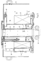
- Figures 1 and 2 show a mold 10 contained in a metal housing 12.
- the mold 10 essentially comprises a vertical mold tube 14 containing liquid metal 16 which is poured from a not shown tundish.
- the molten metal 16 gradually solidifies in this ingot mold tube and the metal blank is extracted there by passing through a set 18 of underlying guiding rollers and forming the metal blanks.
- the set of rollers 18 is integral with the ingot mold 10 and can be dismantled in block with the latter.
- the ingot mold tube 14 which generally consists of a copper tube, is surrounded by a coaxial steel tube 20 which forms with the ingot mold tube an annular cylindrical space 22 in which a coolant flows from the ingot mold tube 14.
- Another cylindrical space 24 is delimited around the tube 20 by a second tube 26. This space 24 is closed downwards by an annular plate 28 fixed to the two tubes 20 and 26.
- the cooling water enters the circuit at 30 and then into the annular gap 22 between the mold tube 14 and the tube 20.
- This space is very thin to ensure rapid circulation and efficient cooling in the mold tube 14
- the cooling water thus rises along the ingot mold tube to overflow through the top of the tube 20 and fill the annular space 24.
- the cooling water leaves this space 24 by overflowing in a vertical pipe, not shown, arranged on along the wall inside the tube 26 and then through an outlet pipe.
- the electromagnetic inductor 32 may consist of one or more inductors.
- the inductor 32 is not fixed, but can be moved vertically between an elevated position according to FIG. 1 for free-jet casting and a lower position according to FIG. 2 for casting with submerged nozzle.
- the means for moving the inductor 32 can be constituted by any suitable means known per se, for example three vertical threaded rods which support the inductor 32 and which can be rotated synchronously by a suitable motor.
- the inductor 32 slides vertically in several, for example three guide rods 50, the vertical maneuver being carried out by a crane not shown.
- the rods 50 are designed to position the inductor 32 in three different vertical positions defined by three upper radial perforations 52 and two lower notches 54.
- the inductor 32 rests on the bottom of the mold 10 and can be keyed by the lower perforation 52. If the illustrated embodiment allows a third intermediate position, not shown, it is, of course, possible to n '' plan only two or plan more.
- the inductor 32 can also include a separate cooling circuit, which is symbolized by the arrows 34 and 36 for the inlet and outlet of cooling water.
- Another feature of the present invention is monitoring the level of the meniscus of the liquid metal in the ingot mold tube 14.
- This monitoring is carried out using a radiation source 38, for example a cobalt source, arranged in the upper region of the annular space 24 and which is associated with a scintillometer 40 disposed on the opposite side of the ingot mold tube 14.
- this radiation source 38 is located inside a cylindrical protective jacket 42, as shown in more detail and enlarged in FIG. 3.
- This protective jacket 42 which may, for example, be made of lead, has a vertical slot 44 for the passage of the spokes.
- This protective jacket 42 can be rotated around a vertical axis between an operating position shown in FIG.
Landscapes
- Engineering & Computer Science (AREA)
- Mechanical Engineering (AREA)
- Continuous Casting (AREA)
- Mixers Of The Rotary Stirring Type (AREA)
- General Induction Heating (AREA)
- Manufacture And Refinement Of Metals (AREA)
- Furnace Details (AREA)
Applications Claiming Priority (3)
| Application Number | Priority Date | Filing Date | Title |
|---|---|---|---|
| LU87914A LU87914A1 (fr) | 1991-04-03 | 1991-04-03 | Dispositif de brassage electromagnetique en lingotiere |
| LU87914 | 1991-04-03 | ||
| EP92102888A EP0511465B2 (de) | 1991-04-03 | 1992-02-21 | Elektromagnetische Rühreinrichtung für das Stranggiessen |
Related Parent Applications (2)
| Application Number | Title | Priority Date | Filing Date |
|---|---|---|---|
| EP92102888.2 Division | 1992-02-21 | ||
| EP92102888A Division EP0511465B2 (de) | 1991-04-03 | 1992-02-21 | Elektromagnetische Rühreinrichtung für das Stranggiessen |
Publications (3)
| Publication Number | Publication Date |
|---|---|
| EP0778098A2 true EP0778098A2 (de) | 1997-06-11 |
| EP0778098A3 EP0778098A3 (de) | 1997-10-08 |
| EP0778098B1 EP0778098B1 (de) | 1998-09-30 |
Family
ID=19731286
Family Applications (2)
| Application Number | Title | Priority Date | Filing Date |
|---|---|---|---|
| EP92102888A Expired - Lifetime EP0511465B2 (de) | 1991-04-03 | 1992-02-21 | Elektromagnetische Rühreinrichtung für das Stranggiessen |
| EP97100231A Expired - Lifetime EP0778098B1 (de) | 1991-04-03 | 1992-02-21 | Elektromagnetische Rühreinrichtung für das Stranggiessen |
Family Applications Before (1)
| Application Number | Title | Priority Date | Filing Date |
|---|---|---|---|
| EP92102888A Expired - Lifetime EP0511465B2 (de) | 1991-04-03 | 1992-02-21 | Elektromagnetische Rühreinrichtung für das Stranggiessen |
Country Status (6)
| Country | Link |
|---|---|
| EP (2) | EP0511465B2 (de) |
| AT (2) | ATE171656T1 (de) |
| CA (1) | CA2040830C (de) |
| DE (2) | DE69227206T2 (de) |
| ES (2) | ES2123347T3 (de) |
| LU (1) | LU87914A1 (de) |
Cited By (2)
| Publication number | Priority date | Publication date | Assignee | Title |
|---|---|---|---|---|
| JP2009517218A (ja) * | 2005-11-28 | 2009-04-30 | ロテレツク | 連続鋳造鋳型の高さにわたる電磁気撹拌モードの調整 |
| CN109746404A (zh) * | 2019-03-08 | 2019-05-14 | 石家庄爱迪尔电气有限公司 | 一种便于维护和加工的电磁搅拌铸造设备 |
Families Citing this family (2)
| Publication number | Priority date | Publication date | Assignee | Title |
|---|---|---|---|---|
| IT1288900B1 (it) * | 1996-05-13 | 1998-09-25 | Danieli Off Mecc | Procedimento di colata continua con campo magnetico pulsante e relativo dispositivo |
| CN105964988B (zh) * | 2016-03-19 | 2019-04-02 | 上海大学 | 移动型脉冲磁致振荡细化金属凝固组织方法 |
Citations (3)
| Publication number | Priority date | Publication date | Assignee | Title |
|---|---|---|---|---|
| GB2021459A (en) | 1978-05-26 | 1979-12-05 | Arbed | Apparatus for the electrorotative casting of liquid metal |
| EP0093068A1 (de) | 1982-04-22 | 1983-11-02 | Paul Metz | Verwendung von Kokillen-Ausgüssen |
| DE3819493A1 (de) | 1988-06-08 | 1989-12-14 | Voest Alpine Ind Anlagen | Knueppel- bzw. vorblock-stranggiesskokille |
Family Cites Families (11)
| Publication number | Priority date | Publication date | Assignee | Title |
|---|---|---|---|---|
| AT185038B (de) * | 1951-03-16 | 1956-03-26 | Boehler & Co Ag Geb | Verfahren zur Kühlung von Stranggußkokillen |
| US3153820A (en) * | 1961-10-09 | 1964-10-27 | Charles B Criner | Apparatus for improving metal structure |
| DE1290303B (de) † | 1964-08-22 | 1969-03-06 | Schloemann Ag | Vorrichtung zum Messen des Fuellstandes von Schmelze in einer Stranggiesskokille |
| JPS5719141A (en) * | 1980-07-09 | 1982-02-01 | Mitsubishi Heavy Ind Ltd | Electromagnetic stirring device of continuous casting facility |
| FR2502996A1 (fr) * | 1981-04-03 | 1982-10-08 | Rotelec Sa | Inducteur electromagnetique a champ tournant et equipement de lingotiere de coulee continue des metaux pour son utilisation |
| SE441502B (sv) * | 1984-03-19 | 1985-10-14 | Asea Ab | Nivametare vid kokiller for strenggjutning |
| IT1181219B (it) * | 1984-09-17 | 1987-09-23 | Danieli Off Mecc | Colata continua con agitatori polifunzionali |
| JPS6360056A (ja) † | 1986-08-29 | 1988-03-16 | Nisshin Steel Co Ltd | Ti含有ステンレス鋼の連続鋳造方法および連続鋳造用鋳型 |
| DE3730300A1 (de) † | 1987-09-10 | 1989-03-23 | Aeg Elotherm Gmbh | Verfahren und vorrichtung zum elektromagnetischen ruehren von metallschmelzen in einer stranggiesskokille |
| JPH0351954U (de) † | 1989-09-20 | 1991-05-21 | ||
| GB9003196D0 (en) * | 1990-02-13 | 1990-04-11 | Davy Mckee Sheffield | Continuous casting |
-
1991
- 1991-04-03 LU LU87914A patent/LU87914A1/fr unknown
- 1991-04-19 CA CA002040830A patent/CA2040830C/en not_active Expired - Lifetime
-
1992
- 1992-02-21 EP EP92102888A patent/EP0511465B2/de not_active Expired - Lifetime
- 1992-02-21 DE DE69227206T patent/DE69227206T2/de not_active Expired - Lifetime
- 1992-02-21 AT AT97100231T patent/ATE171656T1/de active
- 1992-02-21 ES ES97100231T patent/ES2123347T3/es not_active Expired - Lifetime
- 1992-02-21 AT AT92102888T patent/ATE158525T1/de active
- 1992-02-21 DE DE69222348T patent/DE69222348T3/de not_active Expired - Lifetime
- 1992-02-21 EP EP97100231A patent/EP0778098B1/de not_active Expired - Lifetime
- 1992-02-21 ES ES92102888T patent/ES2108054T5/es not_active Expired - Lifetime
Patent Citations (3)
| Publication number | Priority date | Publication date | Assignee | Title |
|---|---|---|---|---|
| GB2021459A (en) | 1978-05-26 | 1979-12-05 | Arbed | Apparatus for the electrorotative casting of liquid metal |
| EP0093068A1 (de) | 1982-04-22 | 1983-11-02 | Paul Metz | Verwendung von Kokillen-Ausgüssen |
| DE3819493A1 (de) | 1988-06-08 | 1989-12-14 | Voest Alpine Ind Anlagen | Knueppel- bzw. vorblock-stranggiesskokille |
Cited By (4)
| Publication number | Priority date | Publication date | Assignee | Title |
|---|---|---|---|---|
| JP2009517218A (ja) * | 2005-11-28 | 2009-04-30 | ロテレツク | 連続鋳造鋳型の高さにわたる電磁気撹拌モードの調整 |
| US7938166B2 (en) * | 2005-11-28 | 2011-05-10 | Rotelec | Adjusting the mode of electromagnetic stirring over the height of a continous casting mould |
| CN109746404A (zh) * | 2019-03-08 | 2019-05-14 | 石家庄爱迪尔电气有限公司 | 一种便于维护和加工的电磁搅拌铸造设备 |
| CN109746404B (zh) * | 2019-03-08 | 2021-05-18 | 石家庄爱迪尔电气有限公司 | 一种便于维护和加工的电磁搅拌铸造设备 |
Also Published As
| Publication number | Publication date |
|---|---|
| EP0511465B1 (de) | 1997-09-24 |
| EP0778098B1 (de) | 1998-09-30 |
| EP0511465A3 (en) | 1993-04-21 |
| ATE158525T1 (de) | 1997-10-15 |
| CA2040830A1 (en) | 1992-10-04 |
| LU87914A1 (fr) | 1992-11-16 |
| ES2108054T3 (es) | 1997-12-16 |
| ES2108054T5 (es) | 2004-07-01 |
| ATE171656T1 (de) | 1998-10-15 |
| CA2040830C (en) | 2003-08-19 |
| DE69222348T2 (de) | 1998-02-26 |
| DE69227206D1 (de) | 1998-11-05 |
| EP0511465A2 (de) | 1992-11-04 |
| DE69227206T2 (de) | 1999-04-15 |
| DE69222348D1 (de) | 1997-10-30 |
| EP0778098A3 (de) | 1997-10-08 |
| DE69222348T3 (de) | 2004-07-22 |
| EP0511465B2 (de) | 2003-12-03 |
| ES2123347T3 (es) | 1999-01-01 |
Similar Documents
| Publication | Publication Date | Title |
|---|---|---|
| EP2099576B1 (de) | Hohle strahldüse für das stranggiessen | |
| US3646988A (en) | Induction apparatus for continuous and semicontinuous casting | |
| EP0778098B1 (de) | Elektromagnetische Rühreinrichtung für das Stranggiessen | |
| EP0005676A2 (de) | Elektromagnetisches Rührverfahren beim Stranggiessen | |
| US4324392A (en) | Molten metal pouring device | |
| LU84103A1 (fr) | Systeme de decrassage automatique de busettes pendant la coulee de metaux | |
| FR2632549A1 (fr) | Lingotiere pour la coulee continue de billettes ou de blooms | |
| PL126006B1 (en) | Method of continuously casting pipes and mould therefor | |
| CA1208878A (fr) | Procede et installation de brassage electromagnetique de brames metalliques, notamment d'acier, coulees en continu | |
| EP0767843A1 (de) | Verfahren und vorrichtung zum beschicken eines elektroofens mit flüssigmetall | |
| EP0242347A2 (de) | Vorrichtung zum Giessen einer flüssig-festen Mischung | |
| BE1004121A6 (fr) | Dispositif pour la coulee d'un metal et procede d'utilisation de ce dispositif. | |
| FR2516823A1 (fr) | Procede de coulee electromagnetique ou a refroidissement direct | |
| FR2464771A1 (fr) | Procede et appareillage de coulee de metaux dans un moule fixe sur une cuve basculante | |
| EP0241445A1 (de) | Verfahren und Vorrichtung zum Kühlen von Strangguss aus Metall | |
| EP0370934B1 (de) | Verfahren und Einrichtung zum Versorgen einer Kokille mit geschmolzenem Metall in einer Stranggiesseinrichtung für dünne Vorblöcke | |
| EP0236237B1 (de) | Stranggussanlage für Metall | |
| EP0122904A2 (de) | Schieberverschluss für Behälter in der Stahl-Eisen Industrie oder Metallurgie | |
| EP0393005A2 (de) | Verfahren und Vorrichtung zur Kühlung eines stranggegossenen Metallerzeugnisses | |
| EP0943380A1 (de) | Verfahren und Vorrichtung zum Stranggiessen von Metallen | |
| BE1000221A6 (fr) | Dispositif pour la coulee d'un metal en phase pateuse. | |
| BE1004046A3 (fr) | Dispositif de dosage et de transport d'une masse pulverulente. | |
| EP0452294B1 (de) | Verfahren und Vorrichtung zum Stranggiessen eines Metalls | |
| EP0206869B1 (de) | Stranggiessanlage für dünnes Metallband | |
| SU863159A1 (ru) | Устройство дл защиты струи при непрерывной разливке металла |
Legal Events
| Date | Code | Title | Description |
|---|---|---|---|
| PUAI | Public reference made under article 153(3) epc to a published international application that has entered the european phase |
Free format text: ORIGINAL CODE: 0009012 |
|
| AC | Divisional application: reference to earlier application |
Ref document number: 511465 Country of ref document: EP |
|
| AK | Designated contracting states |
Kind code of ref document: A2 Designated state(s): AT BE CH DE ES FR GB IT LI NL |
|
| PUAL | Search report despatched |
Free format text: ORIGINAL CODE: 0009013 |
|
| AK | Designated contracting states |
Kind code of ref document: A3 Designated state(s): AT BE CH DE ES FR GB IT LI NL |
|
| GRAG | Despatch of communication of intention to grant |
Free format text: ORIGINAL CODE: EPIDOS AGRA |
|
| 17P | Request for examination filed |
Effective date: 19971103 |
|
| 17Q | First examination report despatched |
Effective date: 19980108 |
|
| GRAG | Despatch of communication of intention to grant |
Free format text: ORIGINAL CODE: EPIDOS AGRA |
|
| GRAH | Despatch of communication of intention to grant a patent |
Free format text: ORIGINAL CODE: EPIDOS IGRA |
|
| GRAH | Despatch of communication of intention to grant a patent |
Free format text: ORIGINAL CODE: EPIDOS IGRA |
|
| GRAA | (expected) grant |
Free format text: ORIGINAL CODE: 0009210 |
|
| AC | Divisional application: reference to earlier application |
Ref document number: 511465 Country of ref document: EP |
|
| AK | Designated contracting states |
Kind code of ref document: B1 Designated state(s): AT BE CH DE ES FR GB IT LI NL |
|
| REF | Corresponds to: |
Ref document number: 171656 Country of ref document: AT Date of ref document: 19981015 Kind code of ref document: T |
|
| REG | Reference to a national code |
Ref country code: CH Ref legal event code: EP |
|
| REG | Reference to a national code |
Ref country code: CH Ref legal event code: NV Representative=s name: AMMANN PATENTANWAELTE AG BERN |
|
| GBT | Gb: translation of ep patent filed (gb section 77(6)(a)/1977) |
Effective date: 19981009 |
|
| REF | Corresponds to: |
Ref document number: 69227206 Country of ref document: DE Date of ref document: 19981105 |
|
| REG | Reference to a national code |
Ref country code: ES Ref legal event code: FG2A Ref document number: 2123347 Country of ref document: ES Kind code of ref document: T3 |
|
| PG25 | Lapsed in a contracting state [announced via postgrant information from national office to epo] |
Ref country code: BE Free format text: LAPSE BECAUSE OF NON-PAYMENT OF DUE FEES Effective date: 19990228 |
|
| PLBI | Opposition filed |
Free format text: ORIGINAL CODE: 0009260 |
|
| PLBF | Reply of patent proprietor to notice(s) of opposition |
Free format text: ORIGINAL CODE: EPIDOS OBSO |
|
| 26 | Opposition filed |
Opponent name: CONCAST STANDARD AG Effective date: 19990630 |
|
| BERE | Be: lapsed |
Owner name: S.A. PAUL WURTH Effective date: 19990228 |
|
| PLBF | Reply of patent proprietor to notice(s) of opposition |
Free format text: ORIGINAL CODE: EPIDOS OBSO |
|
| PLBF | Reply of patent proprietor to notice(s) of opposition |
Free format text: ORIGINAL CODE: EPIDOS OBSO |
|
| PLBO | Opposition rejected |
Free format text: ORIGINAL CODE: EPIDOS REJO |
|
| APAC | Appeal dossier modified |
Free format text: ORIGINAL CODE: EPIDOS NOAPO |
|
| APAE | Appeal reference modified |
Free format text: ORIGINAL CODE: EPIDOS REFNO |
|
| REG | Reference to a national code |
Ref country code: GB Ref legal event code: IF02 |
|
| APAC | Appeal dossier modified |
Free format text: ORIGINAL CODE: EPIDOS NOAPO |
|
| APAC | Appeal dossier modified |
Free format text: ORIGINAL CODE: EPIDOS NOAPO |
|
| PLBN | Opposition rejected |
Free format text: ORIGINAL CODE: 0009273 |
|
| STAA | Information on the status of an ep patent application or granted ep patent |
Free format text: STATUS: OPPOSITION REJECTED |
|
| 27O | Opposition rejected |
Effective date: 20030506 |
|
| NLR2 | Nl: decision of opposition |
Effective date: 20030506 |
|
| APAH | Appeal reference modified |
Free format text: ORIGINAL CODE: EPIDOSCREFNO |
|
| REG | Reference to a national code |
Ref country code: GB Ref legal event code: 732E |
|
| REG | Reference to a national code |
Ref country code: CH Ref legal event code: PUE Owner name: SMS DEMAG AKTIENGESELLSCHAFT Free format text: PAUL WURTH S.A.#32 RUE D'ALSACE#1122 LUXEMBOURG (LU) -TRANSFER TO- SMS DEMAG AKTIENGESELLSCHAFT#EDUARD-SCHLOEMANN-STRASSE 4#40237 DUESSELDORF (DE) |
|
| REG | Reference to a national code |
Ref country code: FR Ref legal event code: TP |
|
| NLS | Nl: assignments of ep-patents |
Owner name: SMS DEMAG AG Effective date: 20061005 |
|
| PGFP | Annual fee paid to national office [announced via postgrant information from national office to epo] |
Ref country code: IT Payment date: 20110223 Year of fee payment: 20 Ref country code: NL Payment date: 20110216 Year of fee payment: 20 Ref country code: FR Payment date: 20110302 Year of fee payment: 20 Ref country code: CH Payment date: 20110222 Year of fee payment: 20 Ref country code: AT Payment date: 20110214 Year of fee payment: 20 Ref country code: DE Payment date: 20110218 Year of fee payment: 20 |
|
| PGFP | Annual fee paid to national office [announced via postgrant information from national office to epo] |
Ref country code: GB Payment date: 20110217 Year of fee payment: 20 Ref country code: ES Payment date: 20110222 Year of fee payment: 20 |
|
| REG | Reference to a national code |
Ref country code: DE Ref legal event code: R071 Ref document number: 69227206 Country of ref document: DE |
|
| REG | Reference to a national code |
Ref country code: DE Ref legal event code: R071 Ref document number: 69227206 Country of ref document: DE |
|
| REG | Reference to a national code |
Ref country code: NL Ref legal event code: V4 Effective date: 20120221 Ref country code: CH Ref legal event code: PL |
|
| REG | Reference to a national code |
Ref country code: GB Ref legal event code: PE20 Expiry date: 20120220 |
|
| PG25 | Lapsed in a contracting state [announced via postgrant information from national office to epo] |
Ref country code: DE Free format text: LAPSE BECAUSE OF EXPIRATION OF PROTECTION Effective date: 20120222 |
|
| PG25 | Lapsed in a contracting state [announced via postgrant information from national office to epo] |
Ref country code: GB Free format text: LAPSE BECAUSE OF EXPIRATION OF PROTECTION Effective date: 20120220 |
|
| REG | Reference to a national code |
Ref country code: AT Ref legal event code: MK07 Ref document number: 171656 Country of ref document: AT Kind code of ref document: T Effective date: 20120221 |
|
| REG | Reference to a national code |
Ref country code: ES Ref legal event code: FD2A Effective date: 20130722 |