EP0775679B1 - Apparatus and method for the lenghtwise graphitization of carbon electrode bodies - Google Patents
Apparatus and method for the lenghtwise graphitization of carbon electrode bodies Download PDFInfo
- Publication number
- EP0775679B1 EP0775679B1 EP96308309A EP96308309A EP0775679B1 EP 0775679 B1 EP0775679 B1 EP 0775679B1 EP 96308309 A EP96308309 A EP 96308309A EP 96308309 A EP96308309 A EP 96308309A EP 0775679 B1 EP0775679 B1 EP 0775679B1
- Authority
- EP
- European Patent Office
- Prior art keywords
- metal furnace
- shaped
- furnace sections
- sections
- portions
- Prior art date
- Legal status (The legal status is an assumption and is not a legal conclusion. Google has not performed a legal analysis and makes no representation as to the accuracy of the status listed.)
- Expired - Lifetime
Links
- OKTJSMMVPCPJKN-UHFFFAOYSA-N Carbon Chemical compound [C] OKTJSMMVPCPJKN-UHFFFAOYSA-N 0.000 title description 53
- 229910052799 carbon Inorganic materials 0.000 title description 47
- 238000005087 graphitization Methods 0.000 title description 22
- 238000000034 method Methods 0.000 title description 9
- 239000002184 metal Substances 0.000 description 113
- 238000001816 cooling Methods 0.000 description 24
- XLYOFNOQVPJJNP-UHFFFAOYSA-N water Substances O XLYOFNOQVPJJNP-UHFFFAOYSA-N 0.000 description 23
- 239000000463 material Substances 0.000 description 20
- 230000000694 effects Effects 0.000 description 11
- 239000003570 air Substances 0.000 description 9
- 238000000576 coating method Methods 0.000 description 8
- 229910002804 graphite Inorganic materials 0.000 description 8
- 239000010439 graphite Substances 0.000 description 8
- 239000012080 ambient air Substances 0.000 description 7
- 238000002955 isolation Methods 0.000 description 7
- 230000002093 peripheral effect Effects 0.000 description 7
- 239000007921 spray Substances 0.000 description 7
- VYPSYNLAJGMNEJ-UHFFFAOYSA-N Silicium dioxide Chemical compound O=[Si]=O VYPSYNLAJGMNEJ-UHFFFAOYSA-N 0.000 description 6
- 206010022000 influenza Diseases 0.000 description 6
- 239000007788 liquid Substances 0.000 description 6
- 239000011248 coating agent Substances 0.000 description 5
- 230000001965 increasing effect Effects 0.000 description 5
- PNEYBMLMFCGWSK-UHFFFAOYSA-N aluminium oxide Inorganic materials [O-2].[O-2].[O-2].[Al+3].[Al+3] PNEYBMLMFCGWSK-UHFFFAOYSA-N 0.000 description 4
- 238000010438 heat treatment Methods 0.000 description 4
- 238000009413 insulation Methods 0.000 description 4
- 229910000831 Steel Inorganic materials 0.000 description 3
- 239000011449 brick Substances 0.000 description 3
- 230000000284 resting effect Effects 0.000 description 3
- 239000000377 silicon dioxide Substances 0.000 description 3
- 238000005507 spraying Methods 0.000 description 3
- 239000010959 steel Substances 0.000 description 3
- 229910003481 amorphous carbon Inorganic materials 0.000 description 2
- 239000002826 coolant Substances 0.000 description 2
- 230000002708 enhancing effect Effects 0.000 description 2
- 230000005484 gravity Effects 0.000 description 2
- VNWKTOKETHGBQD-UHFFFAOYSA-N methane Chemical compound C VNWKTOKETHGBQD-UHFFFAOYSA-N 0.000 description 2
- 230000003647 oxidation Effects 0.000 description 2
- 238000007254 oxidation reaction Methods 0.000 description 2
- 239000003973 paint Substances 0.000 description 2
- 230000002829 reductive effect Effects 0.000 description 2
- 229910000975 Carbon steel Inorganic materials 0.000 description 1
- HEFNNWSXXWATRW-UHFFFAOYSA-N Ibuprofen Chemical compound CC(C)CC1=CC=C(C(C)C(O)=O)C=C1 HEFNNWSXXWATRW-UHFFFAOYSA-N 0.000 description 1
- 230000001464 adherent effect Effects 0.000 description 1
- 230000002411 adverse Effects 0.000 description 1
- 229910045601 alloy Inorganic materials 0.000 description 1
- 239000000956 alloy Substances 0.000 description 1
- 239000011230 binding agent Substances 0.000 description 1
- 239000000571 coke Substances 0.000 description 1
- 230000003247 decreasing effect Effects 0.000 description 1
- 230000003111 delayed effect Effects 0.000 description 1
- 239000012777 electrically insulating material Substances 0.000 description 1
- 239000008187 granular material Substances 0.000 description 1
- 239000012212 insulator Substances 0.000 description 1
- 230000002452 interceptive effect Effects 0.000 description 1
- 238000012423 maintenance Methods 0.000 description 1
- 238000004519 manufacturing process Methods 0.000 description 1
- 238000004806 packaging method and process Methods 0.000 description 1
- 230000005855 radiation Effects 0.000 description 1
- 239000011214 refractory ceramic Substances 0.000 description 1
- 239000011819 refractory material Substances 0.000 description 1
- 230000035939 shock Effects 0.000 description 1
- HBMJWWWQQXIZIP-UHFFFAOYSA-N silicon carbide Chemical compound [Si+]#[C-] HBMJWWWQQXIZIP-UHFFFAOYSA-N 0.000 description 1
- 229910010271 silicon carbide Inorganic materials 0.000 description 1
- 229910001220 stainless steel Inorganic materials 0.000 description 1
Images







Classifications
-
- F—MECHANICAL ENGINEERING; LIGHTING; HEATING; WEAPONS; BLASTING
- F27—FURNACES; KILNS; OVENS; RETORTS
- F27D—DETAILS OR ACCESSORIES OF FURNACES, KILNS, OVENS OR RETORTS, IN SO FAR AS THEY ARE OF KINDS OCCURRING IN MORE THAN ONE KIND OF FURNACE
- F27D99/00—Subject matter not provided for in other groups of this subclass
- F27D99/0001—Heating elements or systems
- F27D99/0006—Electric heating elements or system
-
- C—CHEMISTRY; METALLURGY
- C04—CEMENTS; CONCRETE; ARTIFICIAL STONE; CERAMICS; REFRACTORIES
- C04B—LIME, MAGNESIA; SLAG; CEMENTS; COMPOSITIONS THEREOF, e.g. MORTARS, CONCRETE OR LIKE BUILDING MATERIALS; ARTIFICIAL STONE; CERAMICS; REFRACTORIES; TREATMENT OF NATURAL STONE
- C04B35/00—Shaped ceramic products characterised by their composition; Ceramics compositions; Processing powders of inorganic compounds preparatory to the manufacturing of ceramic products
- C04B35/515—Shaped ceramic products characterised by their composition; Ceramics compositions; Processing powders of inorganic compounds preparatory to the manufacturing of ceramic products based on non-oxide ceramics
- C04B35/52—Shaped ceramic products characterised by their composition; Ceramics compositions; Processing powders of inorganic compounds preparatory to the manufacturing of ceramic products based on non-oxide ceramics based on carbon, e.g. graphite
-
- F—MECHANICAL ENGINEERING; LIGHTING; HEATING; WEAPONS; BLASTING
- F27—FURNACES; KILNS; OVENS; RETORTS
- F27D—DETAILS OR ACCESSORIES OF FURNACES, KILNS, OVENS OR RETORTS, IN SO FAR AS THEY ARE OF KINDS OCCURRING IN MORE THAN ONE KIND OF FURNACE
- F27D99/00—Subject matter not provided for in other groups of this subclass
- F27D99/0001—Heating elements or systems
- F27D99/0006—Electric heating elements or system
- F27D2099/0025—Currents through the charge
-
- Y—GENERAL TAGGING OF NEW TECHNOLOGICAL DEVELOPMENTS; GENERAL TAGGING OF CROSS-SECTIONAL TECHNOLOGIES SPANNING OVER SEVERAL SECTIONS OF THE IPC; TECHNICAL SUBJECTS COVERED BY FORMER USPC CROSS-REFERENCE ART COLLECTIONS [XRACs] AND DIGESTS
- Y02—TECHNOLOGIES OR APPLICATIONS FOR MITIGATION OR ADAPTATION AGAINST CLIMATE CHANGE
- Y02E—REDUCTION OF GREENHOUSE GAS [GHG] EMISSIONS, RELATED TO ENERGY GENERATION, TRANSMISSION OR DISTRIBUTION
- Y02E60/00—Enabling technologies; Technologies with a potential or indirect contribution to GHG emissions mitigation
- Y02E60/30—Hydrogen technology
- Y02E60/36—Hydrogen production from non-carbon containing sources, e.g. by water electrolysis
Definitions
- the present invention relates to an apparatus and method for use in the graphitization (LWG) of carbon electrode bodies.
- the present invention relates to an apparatus and method for the lengthwise graphitization of carbon electrode bodies.
- carbon electrode bodies In the well known LWG process, carbon electrode bodies, typically of cylindrical shape, are placed in end-to-end contact to form an electrically conductive column which is supported on, and also covered by, a heat insulating pack medium, e.g. carbon granules, in a furnace which provides an electrical connection at each end of the column. Electrical current, e.g. from a rectiformer, flows through the column of carbon bodies and heats the carbon bodies to graphitization temperature, e.g. 2500°C-3500°C by the Joule effect.
- the carbon electrode bodies, before graphitization are formed of amorphous carbon, e.g. coke and binder, and have been previously baked at 700°C to 1000°C in accordance with conventional practices.
- the amorphous carbon electrode bodies are converted to graphite at high temperatures, up to 3500°C, using very large electrical currents, typically direct current (DC) in the range of 50,000 A to 150,000 A.
- DC direct current
- two furnaces are sometimes arranged side-by-side with the graphitizing electrical current passing up through the electrode column in one furnace then crossing over and passing back through the column in the other furnace.
- Apparatus for carrying out the LWG process is the subject of U.S. Patent 1,029,121.
- Moveable apparatus for carrying out the LWG process is disclosed, for example, in U.S. Patents 4,015,068, 4,394,766 and 4,916,714. Similar apparatus for the manufacture of silicon carbide is disclosed in U.S.
- the time period for heating the carbon electrode to graphitization temperature (2500°C-3500°C) is typically 8-18 hours, after which electrical current is discontinued and cooling of the now graphitized electrode, and the pack material, to a safe handling temperature proceeds.
- the furnace pack material which acts beneficially as a thermal insulator during the graphitization period, inhibits the rapid cooling of the graphitized electrode bodies down to a temperature at which oxidation of the graphite is substantially avoided, e.g. 900°C-1100°C, and also retards the heat wave which passes from the graphite electrode through the pack material. Consequently, long cooling periods are required during which the furnace is, in effect, out of operation.
- a furnace for the graphitization of carbon bodies comprising:
- the present invention comprises a furnace formed of a plurality of electrically isolated U-shaped continuous metal sections arranged in two side-by-side closely adjacent but spaced apart rows which are supported by spaced apart electrically non-conductive ribs which rest on and are affixed to an electrically non-conductive stationary platform, e.g. concrete.
- the metal sections are suitably steel, e.g. plain carbon steel. High alloy steels, e.g. stainless steels are also suitable.
- Carbon electrode bodies arranged in a column and surrounded by particulate thermal insulation medium are supported in the metal furnace sections and held in electrical contact with power heads in the conventional manner so that graphitizing electrical current flows through the carbon electrode bodies to heat the carbon bodies by the Joule effect to graphitization temperature.
- the metal furnace sections are spaced above and away from the stationary base platform to permit air flow under the metal furnace sections.
- the opposing side surfaces of the metal furnace sections, together with intermediate portions of the rib supports, define a vertical flue between each pair of side-by-side closely adjacent metal furnace sections through which ambient air from below the metal furnace sections passes upwardly at increasing velocity, due to the heating of the air by radiation and from contact with the metal furnace sections, and the venturi shape of the flue.
- the sides forming the flue and the bottom of the metal furnace sections are cooled by the flow of ambient air which carries away heat from the pack material in the furnace and the heat front passing from the graphitized electrode bodies through the thermally insulating pack material to the metal furnace sections.
- the provision of a plurality of separate vertical flues results in uniform cooling along the length of the furnace since cross-flows of the cooling air are minimized and the cooling air rises uniformly in each of the flues.
- the result is that the graphitized electrode bodies more rapidly reach a safe temperature (e.g. 900°C-1100°C) at which they can be removed from the pack and furnace.
- Additional heat removal and a more rapid approach to a safe electrode removal temperature is achieved by nozzle spraying the outer surface of the sides of the metal furnace sections opposite the pack material contacting the inner surface of the metal furnace sections with water droplets in an amount to form a covering layer of water on the sprayed sides and also on the adjacent bottom portions of the metal furnace sections.
- the water spraying also additionally and importantly minimizes thermal expansion of the metal furnace sections which slidably rest on the rib supports when the temperature of the metal furnace sections is held to less than 100°C, e.g. 40-50°C due to the maintenance of a layer of water on the metal furnace sections after graphitization of the electrodes has been accomplished.
- a furnace apparatus of the invention for graphitization of carbon bodies is shown at 1 in Figure 1 comprising two of a plurality, which can be 12 or more; of open top U-shaped metal furnace sections 10 arranged in-line in a first row "A".
- the longitudinally opposed U-shaped peripheral end portions 12, 12' of each metal furnace section 10 slidably nest in correspondingly U-shaped apertures 14 of respective vertically oriented rib supports 16 which are made of electrically non-conductive refractory material, e.g. concrete.
- the metal furnace sections 10 preferably have substantially spherically shaped, rounded bottom portions 210 and substantially straight and slightly outwardly tapered side portions 215.
- the metal furnace sections 10 are not affixed to rib supports 16 and are readily insertable and are readily removeable for repair and replacement of the furnace sections 10.
- the vertical, longitudinally spaced apart rib supports 16 are fixedly supported on furnace room floor 18, typically an electrically non-conductive stationary concrete platform, and rib supports 16 maintain the bottoms of metal furnace sections 10 spaced above the furnace floor, eg. 15.24cms to 60.96cms (1 ⁇ 2 to 2 feet) to permit the free flow of ambient air.
- Electrically non-conductive dowels 20, suitable case in-place concrete, can be spaced at intervals directly beneath and along the bottom of metal furnace sections 10 to provide additional support while maintaining the space below the metal furnace sections substantially open to permit free air flow.
- Metal furnace sections 10 are not affixed to dowels 20.
- the dowels 20 are suitably about 6 inches in diameter and spaced 91.44cms to 121.92cms (3-4) feet apart so that substantially all of the bottom of metal furnace sections 10 is exposed to ambient air.
- a second row “B” of metal furnace sections 110 is provided parallel, and laterally adjacent, to the first row “A” comprising metal furnace sections 10.
- the metal furnace sections 110 of row “B” are laterally in register with metal furnace sections 10 of the first row "A” and nest in U-shaped apertures 114 of rib supports 16 which are closely laterally adjacent and spaced from U-shaped apertures 14.
- Apertures 14 and 114 are spaced apart by posts 22 which are integral central portions of rib supports 16.
- Posts 22, with adjacent sides 24, 26 of metal furnace sections 10, 110 define individual vertical flues 30 having a flaring, venturi-shaped bottom opening 32, shown in Figure 1A, through which ambient air is drawn upward at increased velocity to provide cooling of the opposed sides and adjacent bottom portions of metal furnace sections 10, 110.
- the stationary metal furnace sections 10, 110 are relatively close together with the separating posts 22 (and also end posts 222) having a width Wp which is about 10% to 20% of the metal furnace section width, Ws.
- the upper opening 31 of flue 30 is substantially less in width than bottom opening 32 to enhance the venturi effect in flue 30.
- metal furnace sections 10, 110 contain pack material 50, e.g. carbon granules introduced from an overhead crane, which supports and covers carbon bodies 52, 152, which are arranged in contact in a column in metal furnace sections 10 and 110.
- Electrical current is conventionally provided from a rectiformer, shown schematically at 54, which passes at 51 through carbon bodies 52 (arranged in metal furnace sections 10), a conventional cross-over mechanism shown schematically at 56, carbon bodies 152 arranged in metal furnace sections 110, and returns to rectiformer 54.
- Cross-over mechanism 56 in addition to conducting current from bodies 52 to bodies 152, can adjustably maintain pressure on the columns (52, 152) as indicated schematically at 53.
- a conventional head electrode (not shown) is positioned between each column and the rectiformer 54.
- the electrical current is typically applied at a level of about 50,000A to 150,000A for a time of about 8 to 18 hours to graphitize the carbon bodies 52, 152, at which time the electrical current is turned off.
- the graphitized carbon electrode bodies 52 are at a temperature of 2500°C to 3500°C when the electrical current is turned off and the graphite electrodes must cool to about 900°C-1100°C before the covering pack material can be safely removed, e.g. by suction from an overhead crane, and the graphitized carbon bodies removed from the furnace without danger of significant oxidation. Furnace operation is re-commenced after removal of pack material, e.g. by suction.
- the length, i.e. duration, of the graphite electrode cooling period to 900°C-1100°C is an important commercial consideration since the furnace is out of operation until it can be emptied of the graphitized carbon bodies.
- the cooling period for a long-standing state-of-the-art LWG furnace shown in Fig. 3 for 55.88cms (22inch) diameter carbon bodies in columns 21.34 metres (70feet) long is about 85 hours to reach 900°C. (See curve "A" of Fig. 4).
- the prior art furnace of Fig. 3 comprises a concrete furnace shell 3 with removable metal sidewalls 5 separated by electrically insulating material 6, e.g. Kaowool, enclosing pack material 7 and carbon electrode bodies 52', 152'.
- the furnace apparatus of Figures 1 and 2 in accordance with the present invention with a plurality of central flues 30 and venturi inlets 32 resulted in a substantially decreased cooling period of 55 hours as illustrated by curve "B" of Figure 4.
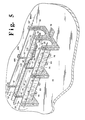
- the sides of metal furnace sections 10, 110 are cooled by the continuous spraying of liquid water droplets 75 from spray nozzles 76 on to the sides of the metal furnace sections 10, 110 in an amount and at a rate so that the water droplets provide a turbulent covering layer of liquid water on the sides and bottom portions of the metal furnace sections 10, 110 opposite pack material 50 as shown in Figure 5A.
- the spray cooling is provided by water from feed conduits 70, 70', 70" which extend adjacently parallel to the outer side walls of the metal furnace sections 10, 110.
- Nozzles 76 on the water feed conduits direct liquid water droplets 75 to the outer side surfaces 79 of metal furnace sections 10, 110 at a location opposite pack material 50 to provide a covering layer of turbulent water flow shown at 63 in Figure 5A on the side surfaces 79 and bottom surfaces 89 of metal furnace sections 10, 110 to cool the metal furnace sections 10, 110 and the pack material 50 in contact therewith to thereby increase the temperature gradient between the graphitized electrodes 52, 152 and the metal furnace sections 10, 110. This increases the rate of cooling of the electrodes 52, 152. Water passes by gravity to furnace room floor platform 18 and is removed for re-cycling via floor drain 78 as shown in Figure 5A. The apparatus of Figure 5 provides a significant lessening of the graphite electrode cooling period as shown at curve "C" in Figure 4.
- Water can be sprayed on the metal furnace sections during the graphitization period (-10 to 0 hours) while electric current is passing through the electrodes, but as a practical matter can be delayed until graphitization is complete (see “I” in Figure 4) since the heat wave from the graphitized electrodes would not reach the metal furnace sections for several hours (see “II” in Figure 4).
- the water spray can be discontinued when the electrode temperature reaches 900°C (see “III” in Figure 4).
- the temperatures for curves A, B, C were measured at the surface of electrodes; for curves D and E the temperatures were measured at the inside surface of the metal furnace sections.
- the water spray is adjusted to provide discrete droplets 75 which impact the metal furnace section outer surface and coalesce to provide a sheet or layer 63 of water flow on the surface of the sides and bottoms of the metal furnace section sections which wets and clings to the surface of the sides and bottoms of the metal furnace sections until draining off by gravity as shown at 68 in Figure 5A.
- Water as thus applied can reduce the temperature of the metal furnace sections to about 40-50°C, as shown in Figure 4, and the air below the metal furnace sections is still sufficiently heated to cause the air to rise through the vertical flues 30 and contribute to the cooling of the metal furnace sections and maintain uniformity of cooling.
- U-shaped open top metal furnace sections 10, 110 are nested in rib supports 416 with respective adjacent terminal portions 12, 12' for engaging U-shaped apertures 414, 514 of vertical refractory rib supports 416.
- a peripheral exterior open channel 450 is provided at the terminal portions 12, 12' of each of the U-shaped metal furnace sections 10, 110 between the terminal portions 12, 12' and rib support 416.
- Each channel 450 of a metal furnace section 10, 110 has a peripheral U-shaped channel metal closure member 460 extending transversely to the metal furnace section.
- a peripheral metal channel side wall or sleeve 470 is provided integral with and transverse to each channel closure member 460 extending adjacently parallel to and spaced from the terminal portion 12, 12' of metal furnace sections (10, 110) to define the open peripheral channel 450 surrounding the terminal portions 12, 12' of the metal furnace sections (10, 110) which is exposed to and receives water sprayed from nozzles 76 and receives coolant water in liquid form as is also shown schematically at 63 in Figure 6A.
- the coolant water spray droplets 75 coalesce form a layer 63 of turbulently flowing liquid on the outer surface of the terminal portions 12, 12' and also channel side walls 470 and closure member 460 to maintain the temperature of terminal portions 12, 12', channel closure elements 460 and channel side walls 470 below 100°C.
- a peripheral flange element 472 is provided integral with the channel side wall 470 to securely engage the rib support 16.
- Peripheral seals can be provided, as shown at 590, to provide firm seating of metal furnace sections (10, 110) in rib support 16.
- Spacing pins 595, suitably made of steel and welded to metal furnace sections (10, 110) and channel side walls 470 can be employed to ensure that channel 450 remains open even if subjected to accidental mechanical shock.
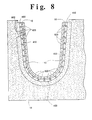
- An embodiment of the invention to achieve this result includes a U-shaped recessed groove 800 provided in the U-shaped aperture 14, 114 of each rib support 16 which is co-extensive with the U-shaped aperture (16, 116).
- Pre-formed refractory ceramic bricks 820 e.g. made of alumina, are set in the recessed groove 800 and extend from the groove 800, as indicated at 830, outwardly beyond the metal furnace sections 10, 10' (and 110, 110') to provide insulation to prevent electric current flow between metal furnace sections 10, 10' (and 110, 110').
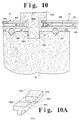
- the pre-formed refractory brick is generally T-shaped as shown in Figures 10, 10A at 1820 and have top cross portions 1822 which rest on the outer surface of metal furnace sections 10, 10' (110, 110') and base portions 1824 perpendicular to the cross portions 1822 which extend into and are fitted into the groove 800.
- the pre-formed bricks 1820 (820) are shaped to conform to the shape of the U-shaped aperture.
- a corrugated cardboard liner 900 similar to the material cardboard cartons, is placed in metal furnace sections 10, 110, contiguous thereto, and carbon granule pack material 50 is confined within the cardboard liner 900, and carbon electrode bodies 52 are covered by the carbon pack material 50. Since the voltage, i.e. electric potential, applied to the carbon electrode bodies 52 during graphitization is relatively low, e.g. 100 volts D.C., the cardboard provides adequate and essentially complete electrical isolation between the carbon electrode bodies 52 and metal furnace sections 10, 110 and the cardboard maintains its physical integrity since temperatures at the metal furnace sections 10, 110 remain at temperatures below 200°C during graphitization due to the intervening carbon pack material (see "T" in Figure 4).
- the heat generated by the Joule effect during graphitization i.e. the heat wave from the electrode bodies, does not reach the metal furnace sections, 10, 110 until several hours after graphitization is complete (see “II” in Figure 4) and the electric voltage applied to the bodies 52 has been turned off.
- the cardboard liner 900 is essentially burned and reduced to char. However, when this occurs there is no longer any need for electrical isolation between the bodies 52 and the metal furnace sections 10, 110.
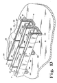
- a further embodiment for providing electrical isolation between carbon bodies 52 and metal furnace sections 10, 110 is shown in Figure 12 in the form of an adherent paint coating 950 on the interior of metal furnace sections 10, 110.
- the dried coating is 0.13mm to 1.3mm (0.005 inch to 0.050 inch) thick and is alumina and/or silica based, ie 50% by weight or more of silica and/or alumina, and is electrically insulating.
- the coating 950 while very thin, is, in view of the relatively low applied voltage, 100 V.D.C., sufficient to electrically isolate carbon bodies 52 from metal furnace sections 10, 110.
- the alumina and/or silica based coating is also thermally insulating, due to its relative thinness 0.13mm to 1.3mm (.005 to .050 inch), there is no significant effect on the cooling of the electrode bodies or pack material 50 in metal furnace sections 10, 110. Therefore, the coating is essentially thermally non-interfering but electrically insulating.
- metal side panels 160 are fixed to the outside posts 222 of the rib support members 16 to provide flues 300 defined by the outermost surfaces 305, 307 of metal furnace sections 10, 110 and outer posts 222 of rib support 16 which leave a lower opening 320 which is wider than flue 300 at its uppermost portion.
- a venturi effect is thus provided by which hot air at the bottom of metal furnace sections 10, 110 is drawn with increasing velocity upwardly through flue 300 to achieve an additional cooling effect.
Landscapes
- Engineering & Computer Science (AREA)
- Chemical & Material Sciences (AREA)
- Ceramic Engineering (AREA)
- Materials Engineering (AREA)
- Manufacturing & Machinery (AREA)
- General Engineering & Computer Science (AREA)
- Mechanical Engineering (AREA)
- Structural Engineering (AREA)
- Organic Chemistry (AREA)
- Carbon And Carbon Compounds (AREA)
- Furnace Details (AREA)
- Vertical, Hearth, Or Arc Furnaces (AREA)
- Ceramic Products (AREA)
- Electrodes For Compound Or Non-Metal Manufacture (AREA)
Applications Claiming Priority (2)
| Application Number | Priority Date | Filing Date | Title |
|---|---|---|---|
| US08/561,369 US5631919A (en) | 1995-11-21 | 1995-11-21 | Apparatus for lengthwise graphitization (LWG) of carbon electrode bodies |
| US561369 | 1995-11-21 |
Publications (3)
| Publication Number | Publication Date |
|---|---|
| EP0775679A2 EP0775679A2 (en) | 1997-05-28 |
| EP0775679A3 EP0775679A3 (en) | 1997-10-29 |
| EP0775679B1 true EP0775679B1 (en) | 2001-03-07 |
Family
ID=24241658
Family Applications (1)
| Application Number | Title | Priority Date | Filing Date |
|---|---|---|---|
| EP96308309A Expired - Lifetime EP0775679B1 (en) | 1995-11-21 | 1996-11-18 | Apparatus and method for the lenghtwise graphitization of carbon electrode bodies |
Country Status (16)
| Country | Link |
|---|---|
| US (1) | US5631919A (pl) |
| EP (1) | EP0775679B1 (pl) |
| JP (1) | JPH09184686A (pl) |
| KR (1) | KR100286958B1 (pl) |
| CN (1) | CN1164636A (pl) |
| BR (1) | BR9605639A (pl) |
| CA (1) | CA2190680C (pl) |
| DE (1) | DE69611971T2 (pl) |
| EG (1) | EG20932A (pl) |
| ES (1) | ES2156984T3 (pl) |
| MY (1) | MY113683A (pl) |
| PL (1) | PL186570B1 (pl) |
| RO (1) | RO118145B1 (pl) |
| RU (1) | RU2129340C1 (pl) |
| TW (1) | TW346538B (pl) |
| ZA (1) | ZA969732B (pl) |
Families Citing this family (16)
| Publication number | Priority date | Publication date | Assignee | Title |
|---|---|---|---|---|
| US6058133A (en) * | 1998-08-19 | 2000-05-02 | Ucar Carbon Company Inc. | Graphite electrodes incorporating stress-relieving slots |
| DE19852090C2 (de) * | 1998-11-12 | 2001-08-02 | Flohe Gmbh & Co | Anlage zur Graphitisierung von Graphitelektroden-Rohlingen |
| EP1279319A1 (en) * | 2000-04-10 | 2003-01-29 | Graphtech Inc. | System for reduction in temperature variation during lengthwise graphitization of carbon bodies |
| KR100738698B1 (ko) | 2004-09-03 | 2007-07-12 | 모딘코리아 유한회사 | 면상 발열체를 구비하는 난방장치 |
| RU2343112C1 (ru) * | 2007-05-17 | 2009-01-10 | Закрытое акционерное общество "УНИХИМТЕК" (ЗАО "УНИХИМТЕК") | Способ получения электроконтактной прокладки (варианты) |
| DE102008025533B3 (de) * | 2008-05-28 | 2009-09-24 | Siemens Aktiengesellschaft | Vorrichtung zur Herstellung von Graphitgegenständen, insbesondere Graphitelektroden |
| WO2010132785A2 (en) | 2009-05-15 | 2010-11-18 | Cummins Filtration Ip, Inc. | Surface coalescer |
| US10058808B2 (en) | 2012-10-22 | 2018-08-28 | Cummins Filtration Ip, Inc. | Composite filter media utilizing bicomponent fibers |
| CN103528369B (zh) * | 2013-09-29 | 2015-06-10 | 成都易态科技有限公司 | 材料烧结器 |
| US10053365B2 (en) * | 2015-04-15 | 2018-08-21 | Showa Denko Carbon Inc. | Graphitization furnace, system, and graphitization method |
| CN105036125B (zh) * | 2015-09-08 | 2017-08-29 | 耿巨泉 | 锂电池负极材料石墨化炉以及石墨化工艺 |
| CN121222126A (zh) | 2016-07-19 | 2025-12-30 | 安美世滤清系统知识产权公司 | 穿孔层聚结器 |
| PL3521740T3 (pl) | 2018-02-02 | 2021-09-06 | Showa Denko Carbon Austria Gmbh | Piec |
| CN111964352B (zh) * | 2020-08-14 | 2021-10-01 | 宁夏永威炭业有限责任公司 | 炭电极两级连续不间断过渡式冷却系统 |
| JP2025512141A (ja) * | 2022-04-13 | 2025-04-17 | イプシロン アドバンスト マテリアルズ プライベート リミテッド | 負極材料の準備のための装置および方法 |
| CN120313353B (zh) * | 2025-06-13 | 2025-08-15 | 山西聚贤石墨新材料有限公司 | 一种石墨电极焙烧装置 |
Family Cites Families (28)
| Publication number | Priority date | Publication date | Assignee | Title |
|---|---|---|---|---|
| CA332950A (en) * | 1933-05-30 | Harris Derby Ira | Carbon graphitizing process | |
| US800515A (en) * | 1904-12-07 | 1905-09-26 | Frank J Tone | Incandescent electrical furnace. |
| US1029121A (en) * | 1909-10-18 | 1912-06-11 | Electrode Company Of America | Apparatus for graphitizing large electrodes. |
| US1198616A (en) * | 1912-06-06 | 1916-09-19 | Nat Carbon Co | Method of heating carbon articles in independent units. |
| US1107478A (en) * | 1913-05-27 | 1914-08-18 | Robert A Bayard | Electric furnace and method of operating the same. |
| CA172848A (en) * | 1916-04-17 | 1916-10-31 | Francis William Pierpont | Fastener |
| US1684611A (en) * | 1925-09-04 | 1928-09-18 | Fed Abrasives Company | Electric furnace for producing silicon carbide |
| US1975259A (en) * | 1929-04-27 | 1934-10-02 | Peter C Reilly | Method of producing graphitic carbon |
| US1884600A (en) * | 1931-04-23 | 1932-10-25 | Peter C Reilly | Induction process of graphitizing carbon |
| US2621218A (en) * | 1951-06-06 | 1952-12-09 | Dow Chemical Co | Electric graphitizing furnace |
| US3284372A (en) * | 1965-09-14 | 1966-11-08 | Great Lakes Carbon Corp | Apparatus and process for continuously making baked and graphitized carbon bodies |
| USRE27018E (en) * | 1969-11-20 | 1971-01-05 | Silicon carbide furnaces and plants | |
| DE2316494B2 (de) * | 1973-04-03 | 1978-05-03 | Sigri Elektrographit Gmbh, 8901 Meitingen | Hochstromwiderstandsofen |
| DE2457923C3 (de) * | 1974-12-07 | 1981-11-05 | Sigri Elektrographit Gmbh, 8901 Meitingen | Graphitierungsofen |
| US4017673A (en) * | 1974-12-17 | 1977-04-12 | Sigri Elektrographit Gmbh | Method and apparatus for graphitization of carbon materials |
| IT1044132B (it) * | 1975-05-26 | 1980-03-20 | Elettrocarbonium Spa | Forno di grafitazione continuo a spostamento della carica in senso verticale |
| GB1517228A (en) * | 1977-03-10 | 1978-07-12 | Post Office | Furnaces |
| US4475207A (en) * | 1981-08-03 | 1984-10-02 | Great Lakes Carbon Corporation | Graphitization furnace loading apparatus |
| US4394766A (en) * | 1981-08-03 | 1983-07-19 | Great Lakes Carbon Corporation | Graphitization system method and apparatus |
| DE3404322C2 (de) * | 1984-02-08 | 1992-08-06 | Sigri GmbH, 8901 Meitingen | Ofenkopf für Graphitierungsofen |
| SU1632939A1 (ru) * | 1986-03-04 | 1991-03-07 | Челябинский Политехнический Институт Им.Ленинского Комсомола | Однофазна установка дл графитации углеродистых изделий |
| IT1191877B (it) * | 1986-04-30 | 1988-03-23 | Elettrocarbonium Spa | Perfezionamento nei forni di grafitazione mobili |
| US4813055A (en) * | 1986-08-08 | 1989-03-14 | Union Carbide Corporation | Furnace cooling system and method |
| GB8908997D0 (en) * | 1989-04-20 | 1989-06-07 | Davy Mckee Stockton | Vessels for containing molten metal |
| AT393499B (de) * | 1990-08-01 | 1991-10-25 | Voest Alpine Mach Const | Verfahren und vorrichtung zum graphitieren von kohlenstoffkoerpern |
| US5117439A (en) * | 1991-03-29 | 1992-05-26 | Ucar Carbon Technology Corporation | Method for operating an electrode graphitization furnace |
| US5299225A (en) * | 1992-05-20 | 1994-03-29 | Sigri Great Lakes Carbon Corp. | Graphitization furnace |
| US5330161A (en) * | 1993-07-08 | 1994-07-19 | Ucar Carbon Technology Corporation | Spray cooled hood system for handling hot gases from a metallurgical vessel utilizing pneumatic processing of molten metal |
-
1995
- 1995-11-21 US US08/561,369 patent/US5631919A/en not_active Expired - Lifetime
-
1996
- 1996-11-18 ES ES96308309T patent/ES2156984T3/es not_active Expired - Lifetime
- 1996-11-18 EP EP96308309A patent/EP0775679B1/en not_active Expired - Lifetime
- 1996-11-18 DE DE69611971T patent/DE69611971T2/de not_active Expired - Lifetime
- 1996-11-19 CA CA002190680A patent/CA2190680C/en not_active Expired - Fee Related
- 1996-11-19 MY MYPI96004796A patent/MY113683A/en unknown
- 1996-11-19 RO RO96-02174A patent/RO118145B1/ro unknown
- 1996-11-19 RU RU96122394A patent/RU2129340C1/ru not_active IP Right Cessation
- 1996-11-20 ZA ZA969732A patent/ZA969732B/xx unknown
- 1996-11-20 PL PL96317091A patent/PL186570B1/pl not_active IP Right Cessation
- 1996-11-20 EG EG102996A patent/EG20932A/xx active
- 1996-11-20 JP JP8309763A patent/JPH09184686A/ja active Pending
- 1996-11-20 KR KR1019960055535A patent/KR100286958B1/ko not_active Expired - Fee Related
- 1996-11-20 BR BR9605639A patent/BR9605639A/pt not_active IP Right Cessation
- 1996-11-20 CN CN96123339A patent/CN1164636A/zh active Pending
-
1997
- 1997-01-07 TW TW086100105A patent/TW346538B/zh not_active IP Right Cessation
Also Published As
| Publication number | Publication date |
|---|---|
| PL186570B1 (pl) | 2004-01-30 |
| TW346538B (en) | 1998-12-01 |
| ZA969732B (en) | 1997-06-12 |
| KR970028409A (ko) | 1997-06-24 |
| RU2129340C1 (ru) | 1999-04-20 |
| MY113683A (en) | 2002-04-30 |
| CA2190680A1 (en) | 1997-05-22 |
| RO118145B1 (ro) | 2003-02-28 |
| US5631919A (en) | 1997-05-20 |
| BR9605639A (pt) | 1998-08-18 |
| EP0775679A2 (en) | 1997-05-28 |
| DE69611971T2 (de) | 2001-07-19 |
| EG20932A (en) | 2000-06-28 |
| ES2156984T3 (es) | 2001-08-01 |
| EP0775679A3 (en) | 1997-10-29 |
| PL317091A1 (en) | 1997-05-26 |
| MX9605697A (es) | 1997-09-30 |
| JPH09184686A (ja) | 1997-07-15 |
| KR100286958B1 (ko) | 2002-06-24 |
| CN1164636A (zh) | 1997-11-12 |
| CA2190680C (en) | 2000-05-02 |
| DE69611971D1 (de) | 2001-04-12 |
Similar Documents
| Publication | Publication Date | Title |
|---|---|---|
| EP0775679B1 (en) | Apparatus and method for the lenghtwise graphitization of carbon electrode bodies | |
| CA1169244A (en) | High temperature box annealing furnace | |
| JP2002221391A (ja) | 耐熱つり下げレンガ | |
| RU96122394A (ru) | Способ продольной графитизации тел угольных электродов (варинты) и устройство для его осуществления (варианты) | |
| JPH059379B2 (pl) | ||
| US4340412A (en) | Float glass forming chamber with externally supported roof | |
| US5117439A (en) | Method for operating an electrode graphitization furnace | |
| CN109477685B (zh) | 熔化炉 | |
| US4704155A (en) | Heating vessel lid construction for a glass melting furnace | |
| FI82309C (fi) | Bakugn foer elektroder. | |
| JP2500206B2 (ja) | セラミックス製品の焼成方法 | |
| JPH027860Y2 (pl) | ||
| JP4921963B2 (ja) | 炉天井及び炉天井の支持部材 | |
| MXPA96005697A (en) | Longitudinal recording equipment (lwg) car electrode deposits | |
| CN110345771A (zh) | 一种正极材料的烧结匣钵、烧结装置及烧结方法 | |
| US4322236A (en) | Float glass forming chamber having low profile roof | |
| US4630280A (en) | Electrode arrangement | |
| US3578300A (en) | Baking furnace | |
| US4340410A (en) | Float glass forming chamber with isolated heating means | |
| US4311508A (en) | Float glass forming chamber with cast roof | |
| JPS6021384Y2 (ja) | 輻射管式熱処理炉 | |
| GB2174985A (en) | Furnace sill cooling | |
| RU2051323C1 (ru) | Высокотемпературная вакуумная печь | |
| JPH0324587Y2 (pl) | ||
| EP0035865A2 (en) | Vertical-shaft type kiln provided with means for transporting goods therethrough |
Legal Events
| Date | Code | Title | Description |
|---|---|---|---|
| PUAI | Public reference made under article 153(3) epc to a published international application that has entered the european phase |
Free format text: ORIGINAL CODE: 0009012 |
|
| AK | Designated contracting states |
Kind code of ref document: A2 Designated state(s): BE DE ES FR GB IT |
|
| PUAL | Search report despatched |
Free format text: ORIGINAL CODE: 0009013 |
|
| AK | Designated contracting states |
Kind code of ref document: A3 Designated state(s): BE DE ES FR GB IT |
|
| 17P | Request for examination filed |
Effective date: 19980404 |
|
| 17Q | First examination report despatched |
Effective date: 19990201 |
|
| GRAG | Despatch of communication of intention to grant |
Free format text: ORIGINAL CODE: EPIDOS AGRA |
|
| 17Q | First examination report despatched |
Effective date: 19990201 |
|
| GRAG | Despatch of communication of intention to grant |
Free format text: ORIGINAL CODE: EPIDOS AGRA |
|
| GRAH | Despatch of communication of intention to grant a patent |
Free format text: ORIGINAL CODE: EPIDOS IGRA |
|
| GRAH | Despatch of communication of intention to grant a patent |
Free format text: ORIGINAL CODE: EPIDOS IGRA |
|
| GRAA | (expected) grant |
Free format text: ORIGINAL CODE: 0009210 |
|
| AK | Designated contracting states |
Kind code of ref document: B1 Designated state(s): BE DE ES FR GB IT |
|
| ITF | It: translation for a ep patent filed | ||
| REF | Corresponds to: |
Ref document number: 69611971 Country of ref document: DE Date of ref document: 20010412 |
|
| ET | Fr: translation filed | ||
| REG | Reference to a national code |
Ref country code: ES Ref legal event code: FG2A Ref document number: 2156984 Country of ref document: ES Kind code of ref document: T3 |
|
| REG | Reference to a national code |
Ref country code: GB Ref legal event code: IF02 |
|
| PLBE | No opposition filed within time limit |
Free format text: ORIGINAL CODE: 0009261 |
|
| STAA | Information on the status of an ep patent application or granted ep patent |
Free format text: STATUS: NO OPPOSITION FILED WITHIN TIME LIMIT |
|
| 26N | No opposition filed | ||
| PGFP | Annual fee paid to national office [announced via postgrant information from national office to epo] |
Ref country code: IT Payment date: 20071128 Year of fee payment: 12 |
|
| PGFP | Annual fee paid to national office [announced via postgrant information from national office to epo] |
Ref country code: BE Payment date: 20071213 Year of fee payment: 12 |
|
| PGFP | Annual fee paid to national office [announced via postgrant information from national office to epo] |
Ref country code: GB Payment date: 20071128 Year of fee payment: 12 |
|
| BERE | Be: lapsed |
Owner name: *UCAR CARBON TECHNOLOGY CORP. Effective date: 20081130 |
|
| GBPC | Gb: european patent ceased through non-payment of renewal fee |
Effective date: 20081118 |
|
| PG25 | Lapsed in a contracting state [announced via postgrant information from national office to epo] |
Ref country code: IT Free format text: LAPSE BECAUSE OF NON-PAYMENT OF DUE FEES Effective date: 20081118 |
|
| PG25 | Lapsed in a contracting state [announced via postgrant information from national office to epo] |
Ref country code: BE Free format text: LAPSE BECAUSE OF NON-PAYMENT OF DUE FEES Effective date: 20081130 |
|
| PG25 | Lapsed in a contracting state [announced via postgrant information from national office to epo] |
Ref country code: GB Free format text: LAPSE BECAUSE OF NON-PAYMENT OF DUE FEES Effective date: 20081118 |
|
| PGFP | Annual fee paid to national office [announced via postgrant information from national office to epo] |
Ref country code: DE Payment date: 20101126 Year of fee payment: 15 |
|
| PGFP | Annual fee paid to national office [announced via postgrant information from national office to epo] |
Ref country code: ES Payment date: 20111124 Year of fee payment: 16 Ref country code: FR Payment date: 20111128 Year of fee payment: 16 |
|
| REG | Reference to a national code |
Ref country code: FR Ref legal event code: ST Effective date: 20130731 |
|
| REG | Reference to a national code |
Ref country code: DE Ref legal event code: R119 Ref document number: 69611971 Country of ref document: DE Effective date: 20130601 |
|
| PG25 | Lapsed in a contracting state [announced via postgrant information from national office to epo] |
Ref country code: DE Free format text: LAPSE BECAUSE OF NON-PAYMENT OF DUE FEES Effective date: 20130601 |
|
| PG25 | Lapsed in a contracting state [announced via postgrant information from national office to epo] |
Ref country code: FR Free format text: LAPSE BECAUSE OF NON-PAYMENT OF DUE FEES Effective date: 20121130 |
|
| REG | Reference to a national code |
Ref country code: ES Ref legal event code: FD2A Effective date: 20140305 |
|
| PG25 | Lapsed in a contracting state [announced via postgrant information from national office to epo] |
Ref country code: ES Free format text: LAPSE BECAUSE OF NON-PAYMENT OF DUE FEES Effective date: 20121119 |