EP0775524B1 - Trennungssystem für Ionenaustauscherpartikel - Google Patents
Trennungssystem für Ionenaustauscherpartikel Download PDFInfo
- Publication number
- EP0775524B1 EP0775524B1 EP96402453A EP96402453A EP0775524B1 EP 0775524 B1 EP0775524 B1 EP 0775524B1 EP 96402453 A EP96402453 A EP 96402453A EP 96402453 A EP96402453 A EP 96402453A EP 0775524 B1 EP0775524 B1 EP 0775524B1
- Authority
- EP
- European Patent Office
- Prior art keywords
- fraction
- resin particles
- separation vessel
- vessel
- separation
- Prior art date
- Legal status (The legal status is an assumption and is not a legal conclusion. Google has not performed a legal analysis and makes no representation as to the accuracy of the status listed.)
- Expired - Lifetime
Links
Images
Classifications
-
- B—PERFORMING OPERATIONS; TRANSPORTING
- B01—PHYSICAL OR CHEMICAL PROCESSES OR APPARATUS IN GENERAL
- B01D—SEPARATION
- B01D15/00—Separating processes involving the treatment of liquids with solid sorbents; Apparatus therefor
- B01D15/08—Selective adsorption, e.g. chromatography
- B01D15/26—Selective adsorption, e.g. chromatography characterised by the separation mechanism
- B01D15/36—Selective adsorption, e.g. chromatography characterised by the separation mechanism involving ionic interaction
- B01D15/361—Ion-exchange
-
- B—PERFORMING OPERATIONS; TRANSPORTING
- B01—PHYSICAL OR CHEMICAL PROCESSES OR APPARATUS IN GENERAL
- B01J—CHEMICAL OR PHYSICAL PROCESSES, e.g. CATALYSIS OR COLLOID CHEMISTRY; THEIR RELEVANT APPARATUS
- B01J47/00—Ion-exchange processes in general; Apparatus therefor
- B01J47/02—Column or bed processes
- B01J47/04—Mixed-bed processes
-
- B—PERFORMING OPERATIONS; TRANSPORTING
- B01—PHYSICAL OR CHEMICAL PROCESSES OR APPARATUS IN GENERAL
- B01J—CHEMICAL OR PHYSICAL PROCESSES, e.g. CATALYSIS OR COLLOID CHEMISTRY; THEIR RELEVANT APPARATUS
- B01J49/00—Regeneration or reactivation of ion-exchangers; Apparatus therefor
- B01J49/10—Regeneration or reactivation of ion-exchangers; Apparatus therefor of moving beds
- B01J49/18—Regeneration or reactivation of ion-exchangers; Apparatus therefor of moving beds of mixed beds
Definitions
- the present invention relates generally to particles of ion exchange resin used in water purification systems and, more particularly, to a dual-stage system and method for separating a mixture of anionic and cationic resin particles.
- Ion exchange resin particles have been used for many years to remove contaminants from water that is used in the steam generating systems of electric power plants. Additionally, ion exchange resins are frequently employed in other areas of the plants to produce purified make-up water, to purify primary coolant by side-stream purification, to purify liquid waste effluents and, in the case of nuclear plants, to purify water in reactor fuel storage pools. High purity water is often required in other industries as well, such as in the electronics industry for washing electronic components that must be absolutely free from impurities during manufacture.
- water is typically passed through a bed of intermixed cationic and anionic resin particles. These resin particles remove ionic impurities from water by a mechanism of selective ion exchange on active sites in the matrix of the resin. This process continues until the active sites become saturated with ionic impurities.
- the resin particles When the ion exchange resins become saturated, they must either be replaced or rejuvenated. Because disposal of spent resin and replacement with new resin is expensive, the resin particles are typically cleaned, such as by ultrasonic cleaning, to remove surface contaminants and are then chemically rejuvenated to restore their ion exchange capabilities.
- Optimal ionic rejuvenation of the resin particles requires that the intermixed cationic and anionic particles first be separated as completely as possible. This is because cationic resin particles are rejuvenated with a very strong acid solution, such as a sulfuric or hydrochloric acid solution, whereas anionic resin particles are rejuvenated with a very strong caustic solution, such as a sodium hydroxide solution. Although some rejuvenation can take place with incomplete separation, when the resins are placed back in service, any cross-contamination of anionic and cationic resins during rejuvenation will have deleterious effects on performance of the resins.
- the principle method of separating a mixture of cationic and anionic exchange resin particles is via controlled hydraulic upflow in a vertical separation vessel. This technique requires that the cationic and anionic resin particles be manufactured with two different sizes and/or densities, thereby imparting different terminal settling velocities to the respective particles.
- the hydraulic upflow in the separation vessel is then calculated so that the cationic resin particles settle to the bottom, while the anionic resin particles are lifted to the top.
- Laminar flow is defined for purposes of this specification as fluid flow having a Reynolds number of less than 2000.
- fluid flow having a Reynolds number of greater than 4000 is considered to be turbulent.
- fluid flow having a Reynolds number of less than 500 is desirable, and fluid flow having a Reynolds number of less than 200 is most preferable.
- the first stage involves introducing the resins into a classifier tank.
- the resins are fluidized with upwardly flowing water, then allowed to settle into segments, the cationic particles generally settling at the bottom of the tank and the anionic particles generally settling at the top of the tank. Selected segments are then removed at various elevations from the classifier tank so that the remaining resin mixture can be more easily separated in the second stage.
- the second stage involves transferring the fluidized resin mixture into the center of a separator column.
- upward laminar hydraulic flow carries the smaller, less dense anionic resin particles to an anion outlet in the upper region of the separator column, while the larger, more dense cationic resin particles settle and are removed at a cation outlet in the lower region of the separator column.
- the resin particles are then sluiced along separate streams to an anion regeneration tank and a cation regeneration tank, respectively.
- the Stengel, III patents both disclose a dual-stage system for effectively separating resin particles, the system is not without disadvantages.
- the classifier tank requires that the resin particles be allowed to settle before segments are removed at various elevations. Settling and removing certain segments slows the separation process and requires a significant amount of action on the part of a person operating the system.
- the Stengel, III patents state that the classifier may be bypassed if desired and the fluidized resin particles may be introduced directly into the separator, this would result in less effective separation. By operating the system without the classifier, the process becomes simpler and faster but does so to the detriment of the completeness of resin particle separation.
- Emmett is also directed to the regeneration of ion exchange materials.
- Emmett provides an intermediate layer of inert resin particles. The interface between the different ionic resin particles is thereby more clearly defined.
- resin particles are subjected to upward hydraulic flow in a first vessel and then allowed to settle so that the cationic particles are separated from the anionic particles by the intermediate layer of inert particles.
- the cationic resin particles are drained from the bottom of the first vessel into a second vessel. Transfer is terminated when the inert particles reach the bottom of the first vessel.
- the anionic and cation particles, respectively are cleaned and rejuvenated separately.
- Emmett discloses two vessels, only the first is used for separation of the resin particles. The second serves only to contain the cationic particles for cleaning and rejuvenation after separation, not for separation itself.
- the Emmett process is not fast and continuous but is slow, requiring the resin particles to be separated one batch at a time. Further, the process requires that each batch of particles be allowed to settle for optimum separation, which also takes a significant amount of time.
- U.S. Patent No. 4,913,803 to Earls et al. and U.S. Patent No. 4,120,786 to Petersen et al. also disclose methods and apparatuses for separating ion exchange resin particles.
- a single vessel is used to separate the different particles in a continuous manner using an upward laminar flow carrier fluid.
- Earls et al. also discloses the use of a sieve to better separate the particles. While these processes are continuous, and therefore expeditious, only one vessel is used. Accordingly, these relatively simple processes are limited in their ability to optimize resin particle separation.
- Pike discloses an ore washer and concentrator, wherein upflow from a supply pipe transports waste or "gangue" from the ore through perforations in a grating element in the bottom of the washer. The ore then falls to the bottom of the washer and is drawn out through a valve, while the waste is raised or lifted through a pipe by a pump. If needed, a second washer or concentrator is provided. If so, the pump for the first washer discharges matter into a second grating, and the pump for the second washer or concentrator is at run at a speed less than that of the pump for the first washer.
- WO-A-95/26231 and US-A-4,913,803 are described devices for separating resin particles in a carrier fluid comprising a vertical separation vessel with an inlet for a mixture of resin particles and outlets for a first and a second fractions of resin particles and a recycle line of the carrier fluid in the separation vessel.
- the first fraction of the resin particles is collected in a collection vessel arranged around the separation vessel.
- an apparatus for continuously separating in an ion exchange resin particles mixture, fractions of resin particles, by carrying upwardly the ion exchange resin particles, in at least one separation vessel in a carrier fluid comprising a first separation stage comprised of
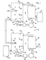
- Figure 1 is a schematic diagram of the two-stage system of the present invention for separating different ion exchange resin particles.
- the present invention is directed to a dual-stage system, generally designated 10, for separating ion exchange resin particles, which are used to purify water in, for example, nuclear power plants.
- the resin particles may be continuously fed into the system 10 for separation; there is no need to separate the particles one batch at a time.
- the system 10 is designed taking into consideration that usually available anionic resin particles ordinarily have a lower terminal settling velocity than cationic resin particles. If inert resin particles are used to provide an intermediate boundary layer, they should have a terminal settling velocity between those of the anionic and cationic particles.
- the anionic resin particles may have a diameter of approximately 500 microns, a specific gravity of approximately 1.07, and a resulting terminal settling velocity of approximately 1,06 cm/s (0.035 ft/sec).
- the cationic particles may have, for example, a diameter of approximately 600 microns, a specific gravity of approximately 1.25, and a resulting terminal settling velocity of approximately 2,74 cm/s (0.09 ft/sec).
- the cationic and anionic resin particles are preferably homogeneously mixed; however, any ratio of cationic particles to anionic particles may be separated using the system 10 of the present invention.
- the dual-stage system 10 of the present invention includes first and second stages, generally indicated by the numerals 12 and 14, respectively, for continuously separating anionic resin particles and cationic resin particles from the mixture thereof.
- the first stage12 separates out a first fraction of anionic resin particles from the mixture.
- the remaining second fraction is then channeled into the second stage14, which separates out a sub-fraction of cationic particles from the second fraction.
- the remaining sub-fraction which includes unseparated anionic and cationic particles, and which may also include inert resin particles, may then be discarded.
- the first stage12 can be seen as including three general sub-components : a first separation vessel 20, a first collection vessel 30, and a carrier fluid recycle line 34 with its associated components.
- the first separation vessel 20 is a vertically oriented tank that is designed to allow larninar or near-laminar upward hydraulic flow through its interior. As discussed earlier, laminar flow is essential for optimal resin particle separation.
- the first collection vessel 20 receives a mixture of ion exchange resin particles in a generally middle elevation of its interior through resin inlet 22. Upwardly flowing hydraulic carrier fluid, such as water, enters the collection vessel 20 through inlet 42 at the bottom of the vessel 20.
- the carrier fluid flows upwardly at, for example, 1,22 cm/s (0.04 ft/sec) through the interior of the vessel 20, as indicated by laminar flow lines 28.
- This causes the anionic particles to separate into a substantially pure first fraction in an upper zone 24 and the cationic particles to separate into a less pure second fraction in a lower zone 44.
- a range of fluid velocities can be used, it is desirable for separation to occur that the carrier fluid flow rate be greater than the terminal settling velocity of the anionic resin particles, yet less than the terminal settling velocity of the cationic resin particles.
- the purity of the resin fractions can be controlled. Increased purity results in more resin being ultimately discarded, whereas less purity results in less resin being discarded. Therefore, the desired economics of resin purity versus discarded resin define the operation of the system 10.
- the first fraction which preferably includes substantially pure anionic resin particles is then directed from the upper zone 24 of the vessel 20 through an upper outlet 26 into the collection vessel 30.
- the collection vessel 30 is optional, the preferred embodiment of the invention 10 includes the collection vessel 30 to allow temporary storage of some volume of the first fraction.
- the collection vessel 30 includes an outlet 32 for draining anionic particles from the collection vessel to a conventional anionic rejuvenation tank 80 containing a caustic solution such as sodium hydroxide.
- the carrier fluid is drained from the collection vessel through a recycle outlet 33, which preferably includes a screen or the like to prevent entry of anionic resin particles, into the fluid recycle line 34.
- the fluid recycle line 34 directs carrier fluid back to the fluid inlet 42 at the bottom of the separation vessel 20 through the action of a first stage recycle pump 36.
- a flow meter 38 is provided in the recycle line 34.
- a throttle valve 40 is provided in the recycle line 34 to adjust the carrier fluid flow rate.
- the pump 36 and throttle valve 40 are adjusted to optimize laminar flow 28 of the carrier fluid upwardly through the separation vessel 20.
- the separation vessel 20 includes an angled flow distributor plate 48 positioned in the bottom of the separation vessel 20 above the fluid inlet 42.
- the flow distributor plate 48 is designed to ensure uniform, evenly distributed laminar flow throughout the entire volume of the separation vessel 20.
- the second fraction of ion exchange resin particles contains mostly cationic resin particles, but may also include inert resin particles (if used) as well as some anionic resin particles that were not completely separated from the mixture in the first stage 12.
- This second fraction may be continuously removed from the lower zone 44 of the separation vessel 20 through a bottom outlet 46 and directed into the second stage 14 of the system 10.
- the flow distributor plate 48 helps direct resin particles into the bottom outlet 46.
- the second stage 14 of the system 10 is preferably configured similarly to the first stage 12, including a second separation vessel 50, a second collection vessel 60, and a second fluid recycle line 64.
- the second separation vessel 50 is also a vertically oriented tank that includes a resin inlet 52 for directing the second fraction of resin particles into a generally middle elevation of the interior of the vessel 50.
- Upwardly flowing hydraulic carrier fluid enters the collection vessel 50 through inlet 72 at the bottom of the vessel 50.
- the carrier fluid flows upwardly at, for example, 2,13 cm/s (0.07 ft/sec) through the interior of the vessel 50, as indicated by laminar flow lines 58. This causes the inert resin particles and unseparated ionic resin particles to separate into a first sub-fraction in an upper zone 54 and the cationic particles to separate into a second, substantially pure sub-fraction in a lower zone 74.
- the carrier fluid flow rate be greater than the terminal settling velocity of any remaining inseparable anionic resin particles, yet less than the terminal settling velocity of the cationic resin particles. It is also preferable, but not necessary, that the carrier fluid flow rate be greater than the terminal settling velocity of any inert resin particles. It is important to note that the fluid velocity in the first separation vessel 20 is preferably different than the fluid velocity in the second separation vessel 50, because the separation vessels are not used in the same manner. The first vessel 20 is used to separate out a substantially pure fraction of anionic resin particles ; whereas, the second separation vessel 50 is used to separate out a substantially pure fraction of cationic resin particles.
- the upper, first sub-fraction is directed from the upper zone 54 of the second separation vessel 50 through an upper outlet 56 into the second collection vessel 60.
- the second collection vessel 60 is optional but preferably included in the second stage 14 to serve as temporary storage of some volume of the first sub-fraction.
- the collection vessel 60 includes a discard outlet 62 for draining the resin particles in the first, relatively impure sub-fraction from the collection vessel 60. This sub-fraction may be discarded, or may undergo further resin particle separation in a later process (not shown).
- the carrier fluid is drained from the second collection vessel 60 through a recycle outlet 63 into the second fluid recycle line 64.
- the fluid recycle line 64 directs carrier fluid back to the fluid inlet 72 at the bottom of the separation vessel 50 through the action of a second stage recycle pump 66 in the recycle line 64.
- a flow meter 68 and a throttle valve 70 are also provided, in the second recycle line 64, which are adjusted to optimize laminar flow 58 of the carrier fluid upwardly through the second separation vessel 50.
- the second separation vessel 50 also includes an angled flow distributor plate 78 positioned in the bottom of the separation vessel 50 above the fluid inlet 72. As in the first separation vessel 20, the flow distributor plate 78 in the second separation vessel 50 is designed to ensure uniform, evenly distributed laminar flow throughout the entire volume of the second separation vessel 50.
- the second sub-fraction which consists of substantially pure cationic resin, may be continuously removed from the lower zone 74 of the second separation vessel 50 through a bottom outlet 76.
- the angled flow distributor plate 78 helps direct resin particles into the bottom outlet 78.
- the cationic resin particles are then directed into a conventional cationic rejuvenation tank 90 containing a strongly acidic solution such as hydrochloric or sulfuric acid.
- the system and method of the invention more completely separates anionic and cationic resin particles than previously designed separation systems.
- One reason for the completeness of separation is through the use of two separation stages that, although preferably similar structurally, operate with different fluid flow parameters. Another reason is because instead of attempting to rejuvenate the sub-fraction of particles that is not entirely separated, this sub-fraction is simply discarded. While this wastes some ion exchange particles, the loss is minimal compared to the problems resulting from incorrect rejuvenation of the particles, caused by incomplete resin particle separation.
Landscapes
- Chemical & Material Sciences (AREA)
- Chemical Kinetics & Catalysis (AREA)
- Organic Chemistry (AREA)
- Analytical Chemistry (AREA)
- Treatment Of Water By Ion Exchange (AREA)
- Separation Of Solids By Using Liquids Or Pneumatic Power (AREA)
Claims (15)
- Vorrichtung zum kontinuierlichen Trennen von Harzpartikel-Anteilen in einer Mischung von Ionenaustauschharzpartikeln durch Beförderung der Ionenaustausch-harzpartikel in mindestens einem Trenngefäß (20) in einem Trägerfluid nach oben, wobei die Vorrichtung eine erste Trennstufe aufweist, die besteht ausdadurch gekennzeichnet, daß sie weiter eine zweite Trennstufe (14) aufweist, die enthält:(a) einem ersten, senkrecht ausgerichteten Trenngefäß (20) mit oberen und unteren Zonen (24, 44), wobei das Gefäß (20) umfaßt: (i) einen Harzeinlaß (22) für die Zufuhr der Mischung von Ionenaustauschharzpartikeln mit unterschiedlichen End-Absetzgeschwindigkeiten ins Innere des ersten Trenngefäßes (20); (ii) einen oberen Auslaß (26) zum Entfernen des ersten Anteils von Harzpartikeln, die eine relativ niedrige End-Absetzgeschwindigkeit aufweisen, aus der oberen Zone (24) des ersten Trenngefäßes (20); und (iii) einen unteren Auslaß (46) zum Entfernen des zweiten Anteils von Harzpartikeln, die eine relativ hohe End-Absetzgeschwindigkeit aufweisen, aus der unteren Zone (44) des Trenngefäßes (20);(b) einem ersten Sammelgefäß (30) zum Auffangen des ersten Anteils von Harzpartikeln von der oberen Zone (24) des ersten Trenngefäßes (20);(c) einer ersten Rückführleitung (34) für den Abfluß von Trägerfluid aus dem ersten Sammelgefäß (30) und zum Leiten des Trägerfluids in das erste Trenngefäß (20) durch einen Fluideinlaß (42) an einem Boden des ersten Trenngefäßes (20); und(d) einer erste Pumpe (36), die in der ersten Rückführleitung (34) angeordnet ist, zum Pumpen des Trägerfluids durch das erste Trenngefäß (20) mit einer Geschwindigkeit nach oben, die größer ist als die End-Absetzgeschwindigkeit des ersten Anteils von Harzpartikeln und geringer als die End-Absetzgeschwindigkeit des zweiten Anteils von Harzpartikeln,ein zweites, senkrecht ausgerichtetes Trenngefäß (30) mit einem Harzeinlaß (52) für die Zufuhr des zweiten Anteils von Harzpartikeln, der mit dem unteren Auslaß (46) des ersten Trenngefäßes (20) verbunden ist, und mit unteren und oberen Innenzonen (54, 74) zum weiteren Trennen des zweiten Anteils von Harzpartikeln,ein zweites Sammelgefäß (60) zum Auffangen eines ersten Unter-Anteils des zweiten Anteils von Harzpartikeln von der oberen Zone (54) des zweiten Trenngefäßes (50) über einen oberen Auslaß (56) des Trenngefäßes (50), undeinen unteren Auslaß (76) für den Abfluß eines zweiten Unter-Anteils des zweiten Anteils von Harzpartikeln aus der unteren Zone (74) des zweiten Trenngefäßes (50).
- Vorrichtung nach Anspruch 1, dadurch gekennzeichnet, daß die zweite Trennstufe (14) weiter eine zweite Rückführleitung (64) zum Rückföhren von Trägerfluid vom oberen Auslaß (56) des zweiten Sammelgefäßes (50) zu einem Fluideinlaß (72) an einem Boden des :zweiten Trenngefäßes (50) aufweist.
- Vorrichtung nach Anspruch 2, dadurch gekennzeichnet, daß sie eine zweite Pumpe (66) aufweist, die in der zweiten Rückführleitung (64) angeordnet ist, um Trägerfluid durch das zweite Trenngefäß (50) mit einer Geschwindigkeit nach oben zu pumpen, die größer ist als die End-Absetzgeschwindigkeit des ersten Unter-Anteils des zweiten Anteils von Harzpartikeln und geringer als die End-Absetzgeschwindigkeit des zweiten Unter-Anteils des zweiten Anteils von Harzpartikeln.
- Vorrichtung nach Anspruch 3, dadurch gekennzeichnet, daß die zweite Pumpe (66) Trägerfluid durch das zweite Trenngefäß (50) mit einer anderen Geschwindigkeit pumpt als die erste Pumpe (36) Trägerfluid durch das erste Trenngefäß (20) pumpt.
- Vorrichtung nach einem der Ansprüche 2 bis 4, dadurch gekennzeichnet, daß das zweite Sammelgefäß (60) einen Rückführfluidauslaß (63) für den Abfluß von Trägerfluid aus dem zweiten Sammelgefäß (60) in die zweite Rückführleitung (64) aufweist.
- Vorrichtung nach Anspruch 5, in der die zweite Rückführleitung (64) einen Durchflußmesser (68) und eine Drosselklappe (70) aufweist.
- Vorrichtung nach einem der Ansprüche 1 bis 6, dadurch gekennzeichnet, daß der untere Auslaß (76) des zweiten Trenngefäßes den zweiten Unter-Anteil des zweiten Anteils von Harzpartikeln vom zweiten Trenngefäß (50) zu einem Regeneriertank (90) leitet.
- Vorrichtung nach Anspruch 7, dadurch gekennzeichnet, daß der zweite Unter-Anteil des zweiten Anteils von Harzpartikeln im wesentlichen kationische Harzpartikel enthält, und der Regeneriertank (90) ein kationischer Regeneriertank ist.
- Vorrichtung nach einem der Ansprüche 1 bis 8, dadurch gekennzeichnet, daß der mit dem zweiten Trenngefäß (50) verbundene Harzeinlaß (52) zwischen dem oberen und dem unteren Auslaß (56, 76) des zweiten Trenngefäßes (50) angeordnet ist.
- Vorrichtung nach einem der Ansprüche 1 bis 9, dadurch gekennzeichnet, daß das zweite Sammelgefäß (60) einen Ausleerauslaß (62) für den Abfluß des ersten Unter-Anteils des zweiten Anteils von Harzpartikeln aus dem zweiten Sammelgefäß (60) aufweist.
- Vorrichtung nach einem der Ansprüche 1 bis 10, dadurch gekennzeichnet, daß das erste Trenngefäß (20) weiter eine erste Strömungsverteilerplatte (48) aufweist, die am Boden des ersten Trenngefäßes (20) angeordnet ist, um eine einheitliche, gleichmäßig verteilte laminare Strömung des Trägerfluids durch das ganze erste Trenngefäß (20) zu gewährleisten.
- Vorrichtung nach einem der Ansprüche 1 bis 11, dadurch gekennzeichnet; daß das zweite Trenngefäß (50) weiter eine Strömungsverteilerplatte (78) aufweist, die am Boden des zweiten Trenngefäßes (50) angeordnet ist, um eine einheitliche, gleichmäßig verteilte laminare Strömung des Trägerfluids durch das ganze zweite Trenngefäß (50) zu gewährleisten.
- Vorrichtung nach einem der Ansprüche 1 bis 12, dadurch gekennzeichnet, daß ein Regeneriertank (80) mit dein Sammelgefäß (30) verbunden ist, um den ersten Anteil von Harzpartikeln vom Sammelgefäß (30) zu empfangen.
- Vorrichtung nach Anspruch 13, dadurch gekennzeichnet, daß der erste Anteil von Harzpartikeln im wesentlichen anionische Harzpartikel enthält und daß der Regeneriertank (80) ein anionischer Regeneriertank ist.
- Verfahren zum kontinuierlichen Trennen von Ionenaustauschharzpartikeln in einer Vorrichtung nach Anspruch 14, die(a) die Partikel im ersten Trenngefäß (20) durch Entfernen eines ersten Anteils von Harzpartikeln aus der oberen Zone (24) und durch Entfernen eines zweiten Anteils von Harzpartikeln aus der unteren Zone (44) des Trenngefäßes (20) trennt;(b) den ersten Harz-Anteil in einem ersten Sammelgefäß (30) auffängt;(c) den ersten Anteil von Harzpartikeln im ersten, mit dem ersten Sammelgefäß (30) verbundenen Regeneriertank (80) auffängt;(d) Trägerfluid vom ersten Sammelgefäß (20) in die erste Rückfhrleitung (34) entleert und das Trägerfluid in das erste Trenngefäß (20) leitet;(e) das Trägerfluid durch das erste Trenngefäß (20) mit einer Geschwindigkeit nach oben pumpt, die größer ist als die End-Absetzgeschwindigkeit des ersten Anteils von Harzpartikeln und geringer als die End-Absetzgeschwindigkeit des zweiten Anteils von Harzpartikeln;(f) die Partikel im zweiten Trenngefäß (50) durch Zufuhr des zweiten Anteils von Harzpartikeln in das Innere des zweiten Trenngefäßes (50) trennt; einen ersten Unter-Anteil des zweiten Anteils von Harzpartikeln, die eine relativ geringe End-Absetzgeschwindigkeit haben, aus der oberen Zone (54) des zweiten Trenngefäßes (50) entfernt und einen zweiten Unter-Anteil des zweiten Anteils von Harzpartikeln, die eine relativ hohe End-Absetzgeschwindigkeit haben, aus der unteren Zone (74) des zweiten Trenngefäßes (50) entfernt;(g) den ersten Unter-Anteil des zweiten Anteils von Harzpartikeln aus der oberen Zone (54) des zweiten Trenngefäßes (50) im zweiten Sammelgefäß (60) auffängt;(h) Trägerfluid aus dem zweiten Sammelgefäß (50) in eine zweite Rückführleitung (64) abfließen läßt und das Trägerfluid in das zweite Trenngefäß (30) leitet;(i) das Trägerfluid durch das zweite Trenngefäß (50) mit einer Geschwindigkeit nach oben pumpt, die größer ist als die End-Absetzgeschwindigkeit des ersten Unter-Anteils des zweiten Anteils von Harzpartikeln und geringer als die End-Absetzgeschwindigkeit des zweiten Unter-Anteils des zweiten Anteils von Harzpartikeln; und(j) den zweiten Unter-Anteil des zweiten Anteils von Harzpartikeln im zweiten Regeneriertank (90) auffängt
Applications Claiming Priority (2)
| Application Number | Priority Date | Filing Date | Title |
|---|---|---|---|
| US08/563,181 US5736052A (en) | 1995-11-27 | 1995-11-27 | Ion exchange resin particle separation system |
| US563181 | 2000-05-02 |
Publications (3)
| Publication Number | Publication Date |
|---|---|
| EP0775524A2 EP0775524A2 (de) | 1997-05-28 |
| EP0775524A3 EP0775524A3 (de) | 1997-08-13 |
| EP0775524B1 true EP0775524B1 (de) | 2001-09-05 |
Family
ID=24249441
Family Applications (1)
| Application Number | Title | Priority Date | Filing Date |
|---|---|---|---|
| EP96402453A Expired - Lifetime EP0775524B1 (de) | 1995-11-27 | 1996-11-15 | Trennungssystem für Ionenaustauscherpartikel |
Country Status (7)
| Country | Link |
|---|---|
| US (1) | US5736052A (de) |
| EP (1) | EP0775524B1 (de) |
| JP (1) | JPH09215942A (de) |
| KR (1) | KR970025712A (de) |
| CA (1) | CA2191358A1 (de) |
| DE (1) | DE69614973D1 (de) |
| TW (1) | TW342355B (de) |
Families Citing this family (9)
| Publication number | Priority date | Publication date | Assignee | Title |
|---|---|---|---|---|
| US6348153B1 (en) | 1998-03-25 | 2002-02-19 | James A. Patterson | Method for separating heavy isotopes of hydrogen oxide from water |
| US7862715B2 (en) | 2004-02-09 | 2011-01-04 | Drake Engineering Incorporated | Apparatus for removing undesirable components from a contaminated solution containing both desirable and undesirable components |
| US7368059B2 (en) * | 2004-02-09 | 2008-05-06 | Drake Engineering Incorporated | Method for preferentially removing monovalent cations from contaminated water |
| US8721894B2 (en) * | 2005-02-07 | 2014-05-13 | Drake Water Technologies, Inc. | Methods for hydrodynamic control of a continuous water purification system |
| US20050173314A1 (en) * | 2004-02-09 | 2005-08-11 | Drake Ronald N. | Controlled liquid purification system |
| US6984327B1 (en) | 2004-11-23 | 2006-01-10 | Patterson James A | System and method for separating heavy isotopes of hydrogen oxide from water |
| AU2013204708B2 (en) * | 2012-05-25 | 2016-11-03 | Ixom Operations Pty Ltd | Water Treatment Process |
| US9931584B2 (en) | 2015-02-10 | 2018-04-03 | Drake Water Technologies, Inc. | Methods and apparatus for counter-current leaching of finely divided solids |
| US9833790B2 (en) * | 2015-07-09 | 2017-12-05 | Jesse W. Rhodes, JR. | Assembly and method for gravitationally separating gold from small particles |
Family Cites Families (46)
| Publication number | Priority date | Publication date | Assignee | Title |
|---|---|---|---|---|
| US11377A (en) * | 1854-07-25 | Improved steam-boiler | ||
| US458837A (en) * | 1891-09-01 | Ore washer and concentrator | ||
| GB189900350A (en) * | 1899-01-06 | 1899-12-02 | George Fischer | A New or Improved Method of and Means for the Concentration or Separation and Amalgamation of Crushed Ores or Mineral Slimes. |
| US2744840A (en) * | 1950-06-16 | 1956-05-08 | Holly Sugar Corp | Sugar purification ion exchange method and apparatus |
| US2767140A (en) * | 1954-10-07 | 1956-10-16 | Dorr Oliver Inc | Continuous ion exchange treatment |
| US3261559A (en) * | 1961-08-07 | 1966-07-19 | Consolidation Coal Co | Gravity separation of coal ore |
| FR1379797A (fr) * | 1963-10-17 | 1964-11-27 | Commissariat Energie Atomique | Procédé pour le traitement d'un liquide |
| US3298950A (en) * | 1964-04-13 | 1967-01-17 | Ritter Pfaudler Corp | Liquid treating apparatus and method |
| US3429807A (en) * | 1966-12-08 | 1969-02-25 | William R Burgess | Method of regenerating ion exchange material from service demineralizers |
| US3414508A (en) * | 1967-03-21 | 1968-12-03 | Crane Co | Condensate purification process |
| US3385787A (en) * | 1967-04-03 | 1968-05-28 | Crane Co | Condensate purification process |
| US3583908A (en) * | 1968-09-25 | 1971-06-08 | Crane Co | Condensate purification process |
| US3595385A (en) * | 1969-06-02 | 1971-07-27 | Union Tank Car Co | Method and apparatus for controlling levels in an ion exchange resin separator |
| US3660282A (en) * | 1969-06-17 | 1972-05-02 | Ecodyne Corp | Method and apparatus for regenerating mixed beds of ion exchange resins |
| US3582504A (en) * | 1970-04-20 | 1971-06-01 | Ecodyne Corp | Method for separating and isolating ion exchange resins |
| US4088563A (en) * | 1970-06-16 | 1978-05-09 | Hager & Elsaesser | Process for the treatment of water solution by ion exchange |
| US3700592A (en) * | 1970-12-04 | 1972-10-24 | Aerojet General Co | Process for the removal and recovery of mineral pollutants from water |
| US3775310A (en) * | 1971-03-12 | 1973-11-27 | Continuous ion exchange | |
| BE786184A (fr) * | 1971-08-09 | 1973-01-12 | Degremont | Perfectionnements apportes aux appareils pour la separation en continu de resines echangeuses d'ions de densites differentes |
| US3826761A (en) * | 1972-03-01 | 1974-07-30 | Ecodyne Corp | Method of separating cation and anion exchange resins |
| US3797660A (en) * | 1972-06-23 | 1974-03-19 | Ecodyne Corp | Ion exchange resin separation apparatus and method employing sonic means to sense resin level |
| US4111798A (en) * | 1976-11-30 | 1978-09-05 | Battelle Development Corporation | Separation of solids by varying the bulk density of a fluid separating medium |
| DE2702987B1 (de) * | 1977-01-26 | 1978-05-18 | Steinmueller Gmbh L & C | Verfahren zur Trennung von koernigen Schuettguetern unterschiedlicher Dichten in einem gasfoermigen oder fluessigen Medium |
| US4120786A (en) * | 1977-03-29 | 1978-10-17 | General Electric Company | Separation of mixed ion exchange resins |
| NL185708C (nl) * | 1977-05-27 | 1990-07-02 | Northern Eng Ind | Werkwijze voor de regeneratie van ionenwisselaars. |
| US4191644A (en) * | 1978-05-11 | 1980-03-04 | Belco Pollution Control Corporation | Regeneration of mixed resin bed used for condensate polishing |
| CH629119A5 (de) * | 1978-07-14 | 1982-04-15 | Foerderung Forschung Gmbh | Vorrichtung zum trennen von gemengen aus feststoffteilchen verschiedener dichte. |
| JPS55134690A (en) * | 1979-04-07 | 1980-10-20 | Ebara Infilco Co Ltd | Mixed resin separation device in water treatment |
| US4301001A (en) * | 1979-05-21 | 1981-11-17 | English Clays Lovering Pochin & Company, Limited | Process for concentrating mica in a mixture of sand and mica |
| US4287088A (en) * | 1979-08-21 | 1981-09-01 | Hydrocarbon Research, Inc. | Multi-stage fluidization and segregation of used catalyst fractions |
| US4264439A (en) * | 1979-10-09 | 1981-04-28 | The Dow Chemical Company | Separation of anion and cation exchange resins in a mixed resin bed |
| US4263145A (en) * | 1980-06-10 | 1981-04-21 | The Dow Chemical Company | Recovery of ammonia or amine from a cation exchange resin |
| AU548884B2 (en) * | 1981-03-05 | 1986-01-09 | Northern Engineering Industries Plc | Regenerating ion-exchange materials |
| US4388417A (en) * | 1981-10-26 | 1983-06-14 | Ecodyne Corporation | Regeneration of deep bed condensate polishers |
| US4472282A (en) * | 1981-12-07 | 1984-09-18 | Crane Co. | Mixed bed polishing process |
| IE53992B1 (en) * | 1982-03-30 | 1989-05-10 | Northern Eng Ind | Regeneration of ion exchange materials |
| US4427550A (en) * | 1982-03-31 | 1984-01-24 | Commonwealth Scientific And Industrial Research Organization | Regeneration of adsorbents |
| US4746422A (en) * | 1985-07-26 | 1988-05-24 | Rutgers University | Method for the separation of a mixture of plastic and contaminant |
| US4663051A (en) * | 1985-10-11 | 1987-05-05 | The Graver Company | Regeneration of mixed bed demineralizers |
| JPH0659412B2 (ja) * | 1986-12-25 | 1994-08-10 | 株式会社荏原製作所 | イオン交換樹脂の分離移送方法 |
| US4913803A (en) * | 1988-04-07 | 1990-04-03 | Radiological & Chemical Technology, Inc. | Particle separation system |
| US4961843A (en) * | 1989-04-10 | 1990-10-09 | Lewis Robert M | Lewis econosizer for hydraulically classifying particles |
| US5212205A (en) * | 1992-02-04 | 1993-05-18 | The Graver Company | Regeneration of deep bed condensate polishers |
| US5392921A (en) * | 1992-04-07 | 1995-02-28 | Aks, Incorporated | Process and apparatus for processing resins |
| US5297683A (en) * | 1992-04-07 | 1994-03-29 | Aks, Inc. | Process and apparatus for processing resins |
| US5196122A (en) * | 1992-08-10 | 1993-03-23 | The Graver Company | External regeneration system for mixed bed ion exchangers |
-
1995
- 1995-11-27 US US08/563,181 patent/US5736052A/en not_active Expired - Lifetime
-
1996
- 1996-11-15 DE DE69614973T patent/DE69614973D1/de not_active Expired - Lifetime
- 1996-11-15 EP EP96402453A patent/EP0775524B1/de not_active Expired - Lifetime
- 1996-11-26 CA CA002191358A patent/CA2191358A1/en not_active Abandoned
- 1996-11-27 KR KR1019960057877A patent/KR970025712A/ko not_active Application Discontinuation
- 1996-11-27 JP JP8316459A patent/JPH09215942A/ja not_active Ceased
-
1997
- 1997-02-17 TW TW086101850A patent/TW342355B/zh active
Also Published As
| Publication number | Publication date |
|---|---|
| US5736052A (en) | 1998-04-07 |
| TW342355B (en) | 1998-10-11 |
| KR970025712A (ko) | 1997-06-24 |
| EP0775524A2 (de) | 1997-05-28 |
| CA2191358A1 (en) | 1997-05-28 |
| JPH09215942A (ja) | 1997-08-19 |
| DE69614973D1 (de) | 2001-10-11 |
| EP0775524A3 (de) | 1997-08-13 |
Similar Documents
| Publication | Publication Date | Title |
|---|---|---|
| CA2319566C (en) | Jet pump treatment of heavy oil production sand | |
| US6716344B1 (en) | Liquid-solids circulating fluidized bed | |
| EP0986428A1 (de) | Verfahren und vorrichtung zur rückgewinnung der für chemische und mechanische planarisierung verwendeten wassers und schmirgelpulveremulsion | |
| EP0775524B1 (de) | Trennungssystem für Ionenaustauscherpartikel | |
| EP1089801A1 (de) | Verfahren und vorrichtung für die rückgewinnung von wasser und polierschlamm beim chemischen und mechanischen polieren | |
| US4374028A (en) | Process for waste water purification | |
| JPS59500047A (ja) | 懸濁液、とくに、木材処理産業の処理工程で生じた懸濁液を浄化する方法 | |
| US4636367A (en) | Removal of radium from aqueous liquids | |
| SE431943B (sv) | Cyklisk drift av en bedd av blandade jonbytarhartser | |
| DK162022B (da) | Fremgangsmaade til koncentrering af en suspension af mikroskopiske partikler, apparat til udoevelse af denne fremgangsmaade samt anvendelser af fremgangsmaaden | |
| JPS595015B2 (ja) | イオン交換樹脂の洗浄方法 | |
| US3650948A (en) | Method and apparatus for the continuous regeneration of ion exchange resins | |
| JPS5943150B2 (ja) | 柑橘果汁の減酸装置 | |
| US5297683A (en) | Process and apparatus for processing resins | |
| CA2150591C (en) | Caustic sludge treatment process | |
| US5855691A (en) | Mercury recovery process | |
| US4053397A (en) | Method of recovering backwash liquid with exhausted resin | |
| US5392921A (en) | Process and apparatus for processing resins | |
| CA2322348C (en) | Continuous ion exchange using a liquid-solid circulating fluidized bed | |
| CN104200860B (zh) | 硼回收系统除硼工段冷却剂旋流净化方法与装置 | |
| CN210613098U (zh) | 一种晶体硅机械加工设备的污水循环处理系统 | |
| JPH0767533B2 (ja) | イオン交換樹脂洗浄装置 | |
| AU673688B2 (en) | Recovery of precious metals | |
| WO2003065381A1 (en) | Process and apparatus for volume reduction of oil scale waste | |
| JPH08103795A (ja) | 嫌気性処理装置 |
Legal Events
| Date | Code | Title | Description |
|---|---|---|---|
| PUAI | Public reference made under article 153(3) epc to a published international application that has entered the european phase |
Free format text: ORIGINAL CODE: 0009012 |
|
| AK | Designated contracting states |
Kind code of ref document: A2 Designated state(s): DE FR |
|
| PUAL | Search report despatched |
Free format text: ORIGINAL CODE: 0009013 |
|
| AK | Designated contracting states |
Kind code of ref document: A3 Designated state(s): DE FR |
|
| 17P | Request for examination filed |
Effective date: 19971119 |
|
| 17Q | First examination report despatched |
Effective date: 19990713 |
|
| GRAG | Despatch of communication of intention to grant |
Free format text: ORIGINAL CODE: EPIDOS AGRA |
|
| GRAG | Despatch of communication of intention to grant |
Free format text: ORIGINAL CODE: EPIDOS AGRA |
|
| GRAH | Despatch of communication of intention to grant a patent |
Free format text: ORIGINAL CODE: EPIDOS IGRA |
|
| GRAH | Despatch of communication of intention to grant a patent |
Free format text: ORIGINAL CODE: EPIDOS IGRA |
|
| RAP1 | Party data changed (applicant data changed or rights of an application transferred) |
Owner name: FRAMATOME ANP |
|
| GRAA | (expected) grant |
Free format text: ORIGINAL CODE: 0009210 |
|
| AK | Designated contracting states |
Kind code of ref document: B1 Designated state(s): DE FR |
|
| REF | Corresponds to: |
Ref document number: 69614973 Country of ref document: DE Date of ref document: 20011011 |
|
| PG25 | Lapsed in a contracting state [announced via postgrant information from national office to epo] |
Ref country code: DE Free format text: LAPSE BECAUSE OF FAILURE TO SUBMIT A TRANSLATION OF THE DESCRIPTION OR TO PAY THE FEE WITHIN THE PRESCRIBED TIME-LIMIT Effective date: 20011206 |
|
| ET | Fr: translation filed | ||
| PLBE | No opposition filed within time limit |
Free format text: ORIGINAL CODE: 0009261 |
|
| STAA | Information on the status of an ep patent application or granted ep patent |
Free format text: STATUS: NO OPPOSITION FILED WITHIN TIME LIMIT |
|
| PG25 | Lapsed in a contracting state [announced via postgrant information from national office to epo] |
Ref country code: FR Free format text: LAPSE BECAUSE OF NON-PAYMENT OF DUE FEES Effective date: 20020730 |
|
| 26N | No opposition filed | ||
| REG | Reference to a national code |
Ref country code: FR Ref legal event code: ST |
|
| REG | Reference to a national code |
Ref country code: FR Ref legal event code: ST |