EP0775288B1 - Gaskartousche - Google Patents
Gaskartousche Download PDFInfo
- Publication number
- EP0775288B1 EP0775288B1 EP94923783A EP94923783A EP0775288B1 EP 0775288 B1 EP0775288 B1 EP 0775288B1 EP 94923783 A EP94923783 A EP 94923783A EP 94923783 A EP94923783 A EP 94923783A EP 0775288 B1 EP0775288 B1 EP 0775288B1
- Authority
- EP
- European Patent Office
- Prior art keywords
- sleeve
- cartridge
- gas
- chamber
- expansion chamber
- Prior art date
- Legal status (The legal status is an assumption and is not a legal conclusion. Google has not performed a legal analysis and makes no representation as to the accuracy of the status listed.)
- Expired - Lifetime
Links
- 238000010304 firing Methods 0.000 claims description 8
- 230000002093 peripheral effect Effects 0.000 claims description 7
- 238000000034 method Methods 0.000 claims description 5
- 238000013022 venting Methods 0.000 abstract 1
- 238000004891 communication Methods 0.000 description 1
- 230000000295 complement effect Effects 0.000 description 1
- 230000006835 compression Effects 0.000 description 1
- 238000007906 compression Methods 0.000 description 1
- 238000006073 displacement reaction Methods 0.000 description 1
- 238000004064 recycling Methods 0.000 description 1
- 238000007789 sealing Methods 0.000 description 1
Images


Classifications
-
- F—MECHANICAL ENGINEERING; LIGHTING; HEATING; WEAPONS; BLASTING
- F42—AMMUNITION; BLASTING
- F42B—EXPLOSIVE CHARGES, e.g. FOR BLASTING, FIREWORKS, AMMUNITION
- F42B8/00—Practice or training ammunition
- F42B8/02—Cartridges
-
- F—MECHANICAL ENGINEERING; LIGHTING; HEATING; WEAPONS; BLASTING
- F41—WEAPONS
- F41B—WEAPONS FOR PROJECTING MISSILES WITHOUT USE OF EXPLOSIVE OR COMBUSTIBLE PROPELLANT CHARGE; WEAPONS NOT OTHERWISE PROVIDED FOR
- F41B11/00—Compressed-gas guns, e.g. air guns; Steam guns
- F41B11/60—Compressed-gas guns, e.g. air guns; Steam guns characterised by the supply of compressed gas
- F41B11/62—Compressed-gas guns, e.g. air guns; Steam guns characterised by the supply of compressed gas with pressure supplied by a gas cartridge
-
- F—MECHANICAL ENGINEERING; LIGHTING; HEATING; WEAPONS; BLASTING
- F41—WEAPONS
- F41B—WEAPONS FOR PROJECTING MISSILES WITHOUT USE OF EXPLOSIVE OR COMBUSTIBLE PROPELLANT CHARGE; WEAPONS NOT OTHERWISE PROVIDED FOR
- F41B11/00—Compressed-gas guns, e.g. air guns; Steam guns
- F41B11/70—Details not provided for in F41B11/50 or F41B11/60
- F41B11/72—Valves; Arrangement of valves
- F41B11/721—Valves; Arrangement of valves for controlling gas pressure for both firing the projectile and for loading or feeding
-
- F—MECHANICAL ENGINEERING; LIGHTING; HEATING; WEAPONS; BLASTING
- F42—AMMUNITION; BLASTING
- F42B—EXPLOSIVE CHARGES, e.g. FOR BLASTING, FIREWORKS, AMMUNITION
- F42B6/00—Projectiles or missiles specially adapted for projection without use of explosive or combustible propellant charge, e.g. for blow guns, bows or crossbows, hand-held spring or air guns
- F42B6/10—Air gun pellets ; Ammunition for air guns, e.g. propellant-gas containers
Definitions
- the present invention relates to a method in which a cartridge is used to initiate the recycling of an automatic or semi-automatic firearm and to a cartridge for use in the method.
- Pressurised gas cartridges are also known from, for example, FR-A-2 403 536 and EP-A-499 332, but are incapable of generating sufficient rearward force to actuate recoil-operated automatic and semi-automatic firearms.
- a cartridge in which a cartridge is used to recycle an automatic or semi-automatic firearm, gas under pressure used to expel a projectile passes from a main chamber in a body of the cartridge through a passage, and a rearwardly directed force generated by the cartridge is applied to the breech block;
- the method is characterised in that compressed gas contained in the main chamber is released when the cartridge is fired and passes from the passage into an expansion chamber defined by a sleeve telescopically surrounding the body, to cause the sleeve and body to move relative to each other, whereby the cartridge applies force to the breech block, a valve member extending from the body being progressively withdrawn from an aperture in a forward radial wall of the sleeve as such movement takes place, the valve member preventing discharge of gas from the expansion chamber until a predetermined amount of relative movement has taken place between the body and sleeve, whereupon the aperture is opened and gas is discharged therethrough.
- FR-A-2 403 536 discloses a cartridge comprising a body and a sleeve which telescopically surrounds the body; the body having a peripheral wall and also a forward radial wall enclosing a main chamber in which compressed gas is contained when the cartridge is in use, the forward radial wall having a passage extending therethrough to define a path for gas to leave the chamber, the sleeve having a peripheral wall surrounding the peripheral wall of the body and also a forward radial wall disposed forwardly of the forward radial wall of the body, the forward radial wall of the sleeve having therein an aperture, a first valve being provided to release gas from the main chamber when the cartridge is filed.
- a cartridge in accordance with another aspect of the invention is characterised in comparison with FR-A-2 403 536 in that an expansion chamber is defined between the forward radial walls of the sleeve and body respectively, and a valve member is arranged normally to close the aperture in the forward radial wall of the sleeve and to open the aperture in response to a predetermined amount of relative movement between the body and sleeve which takes place as gas enters the expansion chamber from the main chamber, thereby to discharge gas forwardly from the expansion chamber.
- gas to be used to eject a projectile is admitted to the expansion chamber.
- the pressure of gas in the expansion chamber acts on the end wall of the body and drives the body rearwardly in the manner of a piston to apply force to the breech block.
- the sleeve is held in place by engagement with the wall of the chamber of the weapon.
- the gas is subsequently discharged from the expansion chamber and used to eject the bullet or other projectile. The moment at which the gas is discharged from the expansion chamber is determined by the sleeve and body entering predetermined relative positions.
- the valve may take the form of a spigot which extends axially from the body and normally projects into and obturates the aperture in the radial wall of the sleeve.
- the relative movement between the sleeve and body leads to the spigot being progressively withdrawn from the aperture until, in said predetermined relative positions of the body and sleeve, the spigot is withdrawn from the aperture and the gas from the expansion chamber exhausts through it.
- the bullet or other projectile may be held in place by a rim of the sleeve in a conventional way, it may alternatively be fitted to the spigot from which it is released at the instant the pressurised gas is applied to the projectile.
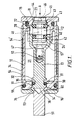
- a cartridge has a two-part case formed from a body 10 and a sleeve 14 mounted telescopically on the body.
- the sleeve has a radially inwardly extending wall 16 at its forward end which bounds an aperture 53.
- the body 10 defines a primary chamber 21 for containing gas under pressure. Because the cylindrical portion of the sleeve is not under any gas pressure it may have a relatively thin wall.
- the body is provided at its forward end with an external annular shoulder 54 arranged to cooperate with an internal shoulder 54' at the rearward end of the sleeve in order to limit relative movement of the two parts.
- An 0-ring 55 seals the body to the sleeve at their forward ends.
- the body has a radially inwardly extending wall 33 at its forward end which in the charged state is in close contact with the end wall of the sleeve.
- An axial spigot 51 projects from the wall 33 and is a sliding fit in the aperture 53.
- a cavity in the inner side of the wall 33 has a cylindrical portion which serves as a seat for the head 36 of a piston valve having a stem 13.
- the end wall of the cavity is conical in shape and formed with ports 34 opening into an annular V-sectioned groove in the outer surface of the end wall 33.
- the groove 60 forms a part of an expansion chamber to be described later.
- the valve head 36 is formed with a pair of collars 31, 32 defining a groove which receives an 0-ring sealing the valve head against the cavity.
- An insert 11 is screwed into the rearward end of the body and is sealed relative to the body by an 0-ring 15.
- the insert has a cylindrical extension which defines a bore 20 which guides a skirt portion 57 at the rearward end of the stem 13.
- the primary gas chamber 21 surrounding the piston valve contains a gas, conveniently air, under a pressure which is preferably at least 50 bar (5x10 7 Pa) and more preferably substantially 200 bar (2x10 7 Pa).
- the piston valve Upon the cartridge being fired, the piston valve is moved rearwardly, initially into the position shown in Figure 2.
- the valve head 36 is therefore withdrawn from the cavity 35 and frees the ports 34.
- Gas from the primary chamber escapes into the groove 60 and causes the body to begin its rearward movement relative to the sleeve.
- This movement begins the enlargement of an expansion chamber 61 which continues to enlarge as rearward movement of the body continues.
- Gas is prevented from escaping between the body and sleeve by the 0-ring 55.
- the spigot slides back through the aperture 53 until eventually it is withdrawn completely therefrom into the position shown in Figure 3.
- the air from the expansion chamber now escapes through the aperture 53 and ejects any projectile carried by the cartridge.
- the projectile may be held in place by a lip on the rim of the wall 16, or may be provided with a socket which receives the spigot 51.
- the body and sleeve are in their closed positions with the two end walls juxtaposed.
- a relief valve which comprises a spool member supported within the skirt 57 of the piston valve.
- the spool member has a central body portion 12 and forward and rearward shoulders 42, 43 defining grooves for receiving 0-rings 40, 41.
- a stem portion extends rearwardly from the shoulder 43 and is located within a relief passage 23.
- Frusto-conical valve seats 44 in the relief passage 23 are contacted by a complementary portion of the rearward shoulder and by the rearward 0-ring.
- the forward 0-ring 40 is sealed against the bore within the skirt 57.
- a compression spring 50 applies a relatively weak pressure to the spool member.
- Two chambers are thereby formed, namely a secondary chamber 22 located between the end of the skirt 57 and the seal ring 41 and third chamber 47 located within the skirt 57 forwardly of the shoulder 42.
- the chamber 22 is in communication with the primary chamber 21 through a bleed passage existing between the skirt and the bore 20, so that in the charged state the pressures within the chambers 21 and 22 are equalised.
- a duct 46 extends through the spool member to connect the chamber 47 to a vent in the peripheral surface of the stem portion, whereby the chamber 47 is at atmospheric pressure.
- Gas in the chamber 22 vents to atmosphere through the relief passage. Although some gas flows through the bleed passage 24 from chamber 21, this flow is negligible and does not prevent the pressure in the chamber 22 falling sharply.
- the gas in chamber 21 applies pressure to the forward surface of the skirt 57 which greatly overcomes that applied by gas in chamber 22 to the rearward rim of the skirt, and the piston valve tends to move rearwards, as discussed above.
- the time at which gas is released and the projectile discharged may be adjusted relative to the rearward motion of the body.
- the cartridge according to the invention is reusable, it is very suitable for use as training ammunition, particularly for semi-automatic pistols and other recoil-operated weapons.
- the cartridge may also be particularly suitable for use in paint-ball guns, because the ball may be adapted easily to fit on the spigot 51.
- the cartridge has been described as being used to eject a projectile, it will be appreciated that it may be used as a "blank" without a projectile but will still be capable of applying force to the breech block.
- Valve arrangements other than those shown may be used to admit gas to the expansion chamber in response to the cartridge being struck by the firing pin, and to discharge gas from the expansion chamber at the desired instant.
Landscapes
- Engineering & Computer Science (AREA)
- General Engineering & Computer Science (AREA)
- Solid-Sorbent Or Filter-Aiding Compositions (AREA)
- Sampling And Sample Adjustment (AREA)
- Feeding And Controlling Fuel (AREA)
- Filling Or Discharging Of Gas Storage Vessels (AREA)
- Toys (AREA)
- Safety Valves (AREA)
- Portable Nailing Machines And Staplers (AREA)
Claims (5)
- Verfahren, wobei eine Kartusche dazu verwendet wird, einen automatischen oder halbautomatischen Feuerhebel hin- und hergehen zu lassen, wobei Gas, das unter Druck steht, um ein Projetil auszustoßen, beim Zünden der Kartusche von einer Hauptkammer (21) in einem Gehäuse (10) der Kartusche durch einen Kanal (34) strömt, und eine nach rückwärts gerichtete Kraft, die von der Kartusche erzeugt wird, auf den Verschluß aufgebracht wird, dadurch gekennzeichnet, daß in der Hauptkammer enthaltenes komprimiertes Gas dann freigegeben wird, wenn die Kartusche gezündet wird, und durch den Kanal in eine Expansionskammer (61) eintritt, gebildet aus einer Buchse (14), die teleskopisch das Gehäuse (10) umgibt, um die Buchse (14) und das Gehäuse (10) relativ zueinander sich bewegen zu lassen, wobei die Kartusche eine Kraft auf den Verschluß aufbringt, wobei ein Ventil (51), das sich vom Gehäuse aus erstreckt, progressiv von einer Öffnung (53) in einer vorderen radialen Wand (16) der Buchse dann zurückgezogen wird, wenn eine solche Bewegung stattfindet, wobei das Ventil eine Abgabe von Gas aus der Expansionskammer (61) so lange unterbindet, bis ein bestimmtes Maß der Relativbewegung zwischen dem Gehäuse und der Buchse stattgefunden hat, worauf die Öffnung geöffnet und Gas durchgelassen wird.
- Kartusche mit einem Gehäuse (10) und einer Buchse (14), die teleskopisch das Gehäuse umgibt, wobei das Gehäuse eine Umfangswand und eine vordere Radialwand (33) aufweist, die eine Hauptkammer (21) umschließt, in welcher komprimiertes Gas dann enthalten ist, wenn sich die Kartusche im Gebrauch befindet, wobei die vordere radiale Wand (33) einen Kanal (34) aufweist, der sich hindurch erstreckt, um einen Weg für unter Druck stehendem Gas zu schaffen, damit dieses die Kammer (21) verläßt, wobei die Buchse (14) eine Umfangswand aufweist, die die Umfangswand des Gehäuses (10) umgibt, wobei eine vordere radiale Wand (16) der Buchse vor der vorderen radialen Wand (33) des Gehäuses angeordnet ist, wobei die vordere radiale Wand (16) der Buchse eine Öffnung (33) aufweist, wobei ein erstes Ventil (36) vorgesehen ist, um Gas aus der Hauptkammer dann zu entlassen, wenn die Buchse gezündet wird, dadurch gekennzeichnet, daß eine Expansionskammer (61) zwischen den vorderen radialen Wänden (16, 33) der Buchse beziehungsweise des Gehäuses gebildet ist, wobei die Öffnung (53) normalerweise durch ein Ventil (51) abgesperrt ist, wobei das Ventil (51) dazu dient, die Öffnung in Abhängigkeit von einem bestimmten Maß der relativen Bewegung zwischen Gehäuse und Buchse zu öffnen, was dann stattfindet, wenn Gas in die Expansionskammer (61) aus der Hauptkammer (21) eintritt, um damit Gas aus der Expansionskammer nach vorn abzugeben.
- Kartusche nach Anspruch 2, dadurch gekennzeichnet, daß sich das Ventilelement (51) von der vorderen radialen Kammer (33) des Gehäuses (10) aus in die Öffnung (53) in der vorderen radialen Wand der Buchse (14) erstreckt, wobei die Relativbewegung zwischen Buchse und Gehäuse beim Eintritt von Gas in die Expansionskammer dazu führt, daß das Ventil (51) in Bezug auf die Öffnung (53) zurückgezogen wird.
- Kartusche nach Anspruch 3, dadurch gekennzeichnet, daß das Ventil (51) die Gestalt eines Zapfens aufweist, und das ein Projektil eine Fassung aufweist, die den Zapfen aufnimmt.
- Kartusche nach einem der Ansprüche 2 bis 4, dadurch gekennzeichnet, daß in der Wand (33) ein Durchbruch (35) vorgesehen ist, der in die Hauptkammer (21) einmündet und eine konische radiale Wand aufweist, aus welcher mehrere Öffnungen (34) durch die Wand (33) in die Expansionskammer (61) einmünden, wobei ein Ventilkopf (36) im Durchbruch (35) angeordnet ist und vom Durchbruch (35) zurückziehbar ist mittels eines Betätigungsmechanismus in Abhängigkeit von der Bewegung eines Stößels (45), der derart angeordnet ist, daß er von einem Zündstift beaufschlagbar ist, um es komprimiertem Gas zu ermöglichen, aus der Hauptkammer (21) in die Expansionskammer (61) zu entweichen.
Applications Claiming Priority (3)
| Application Number | Priority Date | Filing Date | Title |
|---|---|---|---|
| GB9317040A GB2281118B (en) | 1993-08-16 | 1993-08-16 | Gas cartridge |
| GB9317040 | 1993-08-16 | ||
| PCT/GB1994/001779 WO1995005573A1 (en) | 1993-08-16 | 1994-08-15 | Gas cartridge |
Publications (2)
| Publication Number | Publication Date |
|---|---|
| EP0775288A1 EP0775288A1 (de) | 1997-05-28 |
| EP0775288B1 true EP0775288B1 (de) | 1999-10-20 |
Family
ID=10740586
Family Applications (1)
| Application Number | Title | Priority Date | Filing Date |
|---|---|---|---|
| EP94923783A Expired - Lifetime EP0775288B1 (de) | 1993-08-16 | 1994-08-15 | Gaskartousche |
Country Status (14)
| Country | Link |
|---|---|
| US (2) | US5700972A (de) |
| EP (1) | EP0775288B1 (de) |
| JP (1) | JPH10503275A (de) |
| CN (1) | CN1043925C (de) |
| AT (1) | ATE185898T1 (de) |
| AU (1) | AU682708B2 (de) |
| CA (1) | CA2169565C (de) |
| DE (1) | DE69421295T2 (de) |
| ES (1) | ES2137374T3 (de) |
| GB (1) | GB2281118B (de) |
| GR (1) | GR3031576T3 (de) |
| RU (1) | RU2134399C1 (de) |
| WO (1) | WO1995005573A1 (de) |
| ZA (1) | ZA946159B (de) |
Families Citing this family (45)
| Publication number | Priority date | Publication date | Assignee | Title |
|---|---|---|---|---|
| GB2281118B (en) * | 1993-08-16 | 1997-06-18 | Stylobate Proprietaries Limite | Gas cartridge |
| GB9705363D0 (en) | 1997-03-14 | 1997-04-30 | Pyrotech Munitions Limited | Improvements relating to pyrotechnic ammunition |
| GB9817515D0 (en) * | 1998-08-13 | 1998-10-07 | Saxby Michael E | Self loading gun cartridge |
| GB2341440A (en) | 1998-09-14 | 2000-03-15 | Michael Ernest Saxby | Blank cartridge for self loading guns |
| GB2343240A (en) | 1998-10-26 | 2000-05-03 | Michael Ernest Saxby | Projectiles |
| GB2346201A (en) | 1999-02-01 | 2000-08-02 | Michael Ernest Saxby | Marker projectile |
| US6564719B2 (en) | 1999-08-27 | 2003-05-20 | Lambeth Properties Limited | Training cartridge for a self loading gun |
| GB9920205D0 (en) | 1999-08-27 | 1999-10-27 | Lambeth Pty Ltd | Training cartridge of a self loading gun |
| GB2353584A (en) * | 1999-08-27 | 2001-02-28 | Lambeth Properties Ltd | Blank training cartridge for a self loading gun |
| US6470872B1 (en) * | 2000-04-03 | 2002-10-29 | Benjamin T. Tiberius | Semi-automatic firing compressed-gas gun |
| SE0001588D0 (sv) * | 2000-04-27 | 2000-04-27 | Comtri Ab | Granatpatron |
| RU2185592C2 (ru) * | 2000-09-07 | 2002-07-20 | Ладягин Юрий Олегович | Пневматический патрон многоразового использования |
| US6644295B2 (en) * | 2001-07-03 | 2003-11-11 | Smart Parts, Inc. | Pneumatic assembly for a paintball gun |
| FR2838074B1 (fr) * | 2002-04-08 | 2004-09-17 | Prospection & Inventions | Raccord monobloc pour appareil de fixation a gaz comprime et cartouche de gaz comprime |
| DE20208287U1 (de) * | 2002-05-28 | 2002-09-05 | Hans Eichner Gmbh & Co Kg | Druckgas-Schussvorrichtung |
| KR100448003B1 (ko) * | 2002-08-14 | 2004-09-13 | 국방과학연구소 | 기체포 발사 시스템 |
| US6857423B2 (en) * | 2003-02-11 | 2005-02-22 | Paul Garfield Jong | Paintball marker and kit of parts therefor |
| US6860207B1 (en) | 2003-08-22 | 2005-03-01 | Thomas W. Robertson | Compressible shot shell |
| US7147466B1 (en) | 2003-10-24 | 2006-12-12 | Dentsply International, Inc. | Pressure indicator gel system and method therefore |
| US20050257783A1 (en) * | 2004-05-19 | 2005-11-24 | Tippmann Dennis J Jr | Valve arrangement |
| US20060011184A1 (en) * | 2004-06-18 | 2006-01-19 | Npf Limited | Air balanced exhaust poppet valve with bias closure |
| RU2293279C2 (ru) * | 2004-12-27 | 2007-02-10 | Алексей Иванович Аленин | Пневматический патрон многоразового использования (варианты) |
| US7059316B1 (en) * | 2005-03-08 | 2006-06-13 | Jui-Fu Tseng | Paintball shooting structure for a paintball gun |
| FR2884896B1 (fr) * | 2005-04-26 | 2007-06-29 | Prospection Et D Inv S Techniq | Raccord d'etancheite et ensemble d'un organe de transmission, d'une cartouche de gaz et d'un adaptateur comprenant le raccord |
| US20070181114A1 (en) * | 2006-02-07 | 2007-08-09 | Tippmann Dennis J Jr | Combination non-lethal projectile launcher and flash light |
| CA2669183A1 (en) * | 2006-11-09 | 2008-05-22 | Stanley Fastening Systems, L.P. | Cordless fastener driving device |
| US7654256B2 (en) * | 2008-01-16 | 2010-02-02 | Mu-Sung Huang | Apparatus for rapid loading and firing paintballs |
| US20090194087A1 (en) * | 2008-02-04 | 2009-08-06 | Hsin-Hung Lin | High-pressure pneumatic apparatus |
| US7712464B2 (en) * | 2008-06-04 | 2010-05-11 | Yao-Gwo Gan | Valve for paint ball guns |
| US8430086B2 (en) * | 2009-10-22 | 2013-04-30 | Tippmann Sports, Llc | Non-lethal pistol |
| RU2463541C2 (ru) * | 2010-11-30 | 2012-10-10 | Алексей Валентинович Тимошенко | Автоматический пневматический маркер для игры "пейнтбол" с клапаном бесконтактного запирания подачи газа |
| HK1160582A2 (en) * | 2011-05-30 | 2012-07-20 | Alex Brands Buzz Bee Toys (Hk) Limited | Toy gun compressed air firing shell |
| US8256406B1 (en) * | 2011-06-01 | 2012-09-04 | Kevin Kirkpatrick | Systems and methods for regulating pneumatic gas propulsion |
| DE102011104815B4 (de) * | 2011-06-18 | 2014-01-16 | Diehl Bgt Defence Gmbh & Co. Kg | Manöverpatrone |
| US8365669B1 (en) * | 2011-08-24 | 2013-02-05 | Utm Ip Limited | Training cartridge |
| HK1161810A2 (en) * | 2012-03-01 | 2012-08-03 | APS Limited | Compressed gas pellets |
| CN103499235B (zh) * | 2013-09-17 | 2015-06-10 | 中国船舶重工集团公司第七一〇研究所 | 气动式发射装置 |
| US9420778B1 (en) | 2013-09-30 | 2016-08-23 | Tiberius Technology, Llc | Noise-making apparatus and method |
| US20150241165A1 (en) * | 2014-02-21 | 2015-08-27 | Air Ordnance Llc | Fluid cartridge powered pellet gun |
| US9700779B1 (en) * | 2016-08-15 | 2017-07-11 | Jose Leal | Football throwing apparatus |
| US11262156B2 (en) * | 2019-06-17 | 2022-03-01 | Carl E Caudle | Air gun for conventional metal-jacket bullets |
| US11656063B2 (en) * | 2020-11-12 | 2023-05-23 | General Dynamics OTS—Canada, Inc. | Reduced-energy cartridge with exterior sealing member for fluted chamber |
| FR3128283B1 (fr) * | 2021-10-14 | 2023-09-29 | Cybergun | Munition |
| CN116164591B (zh) * | 2022-09-07 | 2024-12-10 | 福建富兴工业彩弹枪有限公司 | 气动抛掷训练器 |
| CN116447929B (zh) * | 2023-05-25 | 2025-11-11 | 王新明 | 一种空气爆炸装置 |
Family Cites Families (19)
| Publication number | Priority date | Publication date | Assignee | Title |
|---|---|---|---|---|
| US387256A (en) * | 1888-08-07 | pratt | ||
| US2327653A (en) * | 1941-04-23 | 1943-08-24 | Lisle Elmer | Pneumatic cartridge and gun |
| US3830214A (en) * | 1972-01-14 | 1974-08-20 | Mb Ass | Gas weapon including cartridge case with plurality of gas containers therein |
| GB1601917A (en) * | 1976-10-28 | 1981-11-04 | Hilvenna Ltd | Ammunition for small arms |
| FR2394779A1 (fr) * | 1977-06-14 | 1979-01-12 | France Etat | Cartouche de tir a blanc pour arme automatique a culasse inertielle |
| GB1601918A (en) | 1977-09-19 | 1981-11-04 | Hilvenna Ltd | Ammunition for small arms |
| GB2116681B (en) * | 1982-02-27 | 1986-12-10 | Hilvenna Ltd | Air guns and ammunition for air guns |
| GB2153983B (en) * | 1982-02-27 | 1986-12-03 | Hilvenna Ltd | Ammunition for air guns |
| EP0100612A3 (de) * | 1982-07-29 | 1985-01-23 | Hilvenna Limited | Patrone für Handfeuerwaffen mit einer Treibladung, die aus Druckgas besteht |
| EP0158408A3 (de) * | 1984-02-14 | 1987-01-14 | Hilvenna Limited | Patronierte Munition für Handwaffen |
| US4697523A (en) * | 1985-01-11 | 1987-10-06 | Hilvenna Limited | Compressed gas powered ammunition for guns |
| US4686905A (en) * | 1985-07-26 | 1987-08-18 | Attila Szabo | Cartridge for frangible projectile |
| GB2211588B (en) * | 1987-10-23 | 1991-12-11 | Bubb Anthony John Allen | Improvements in air guns |
| US5492063A (en) * | 1990-03-22 | 1996-02-20 | Snc Industrial Technologies Inc. | Reduced energy cartridge |
| SU1774153A1 (ru) * | 1990-07-09 | 1992-11-07 | Ts K I B Sportivno Okhotnicheg | Клапанное устройство отсечки сжатого газа для газобаллонного оружия |
| NL9100257A (nl) * | 1991-02-14 | 1992-09-01 | Michael Ernest Saxby | Met een gasdrukvulling werkende patroonmunitie. |
| DE4131285C2 (de) * | 1991-09-20 | 1997-05-28 | Rheinmetall Ind Ag | Anzünderbuchse für eine Treibladung |
| DE4240273A1 (de) * | 1992-12-01 | 1994-06-09 | Dynamit Nobel Ag | Treibladungsanzünder |
| GB2281118B (en) * | 1993-08-16 | 1997-06-18 | Stylobate Proprietaries Limite | Gas cartridge |
-
1993
- 1993-08-16 GB GB9317040A patent/GB2281118B/en not_active Expired - Fee Related
-
1994
- 1994-08-15 AU AU73882/94A patent/AU682708B2/en not_active Ceased
- 1994-08-15 DE DE69421295T patent/DE69421295T2/de not_active Expired - Fee Related
- 1994-08-15 CA CA002169565A patent/CA2169565C/en not_active Expired - Fee Related
- 1994-08-15 JP JP7506824A patent/JPH10503275A/ja active Pending
- 1994-08-15 EP EP94923783A patent/EP0775288B1/de not_active Expired - Lifetime
- 1994-08-15 US US08/596,303 patent/US5700972A/en not_active Expired - Fee Related
- 1994-08-15 RU RU96105417A patent/RU2134399C1/ru not_active IP Right Cessation
- 1994-08-15 AT AT94923783T patent/ATE185898T1/de not_active IP Right Cessation
- 1994-08-15 ES ES94923783T patent/ES2137374T3/es not_active Expired - Lifetime
- 1994-08-15 WO PCT/GB1994/001779 patent/WO1995005573A1/en not_active Ceased
- 1994-08-15 CN CN94193663A patent/CN1043925C/zh not_active Expired - Fee Related
- 1994-08-16 ZA ZA946159A patent/ZA946159B/xx unknown
-
1997
- 1997-10-02 US US08/942,983 patent/US5962805A/en not_active Expired - Fee Related
-
1999
- 1999-10-21 GR GR990402452T patent/GR3031576T3/el unknown
Also Published As
| Publication number | Publication date |
|---|---|
| AU682708B2 (en) | 1997-10-16 |
| GB2281118B (en) | 1997-06-18 |
| JPH10503275A (ja) | 1998-03-24 |
| ATE185898T1 (de) | 1999-11-15 |
| GB2281118A (en) | 1995-02-22 |
| GR3031576T3 (en) | 2000-01-31 |
| CA2169565C (en) | 1998-09-01 |
| WO1995005573A1 (en) | 1995-02-23 |
| GB9317040D0 (en) | 1993-09-29 |
| US5700972A (en) | 1997-12-23 |
| DE69421295D1 (de) | 1999-11-25 |
| DE69421295T2 (de) | 2000-04-13 |
| EP0775288A1 (de) | 1997-05-28 |
| HK1012701A1 (en) | 1999-08-06 |
| CN1132553A (zh) | 1996-10-02 |
| ES2137374T3 (es) | 1999-12-16 |
| CA2169565A1 (en) | 1995-02-23 |
| CN1043925C (zh) | 1999-06-30 |
| ZA946159B (en) | 1995-03-29 |
| AU7388294A (en) | 1995-03-14 |
| RU2134399C1 (ru) | 1999-08-10 |
| US5962805A (en) | 1999-10-05 |
Similar Documents
| Publication | Publication Date | Title |
|---|---|---|
| EP0775288B1 (de) | Gaskartousche | |
| US4227330A (en) | Breech-loading to muzzle-loading firearm converting device | |
| CA2056389C (en) | Blank cartridge for automatic gun | |
| EP1104541B1 (de) | Patrone für selbstladewaffe | |
| US6415718B1 (en) | Training cartridge for a self loading gun | |
| US9097475B2 (en) | Gas-operated firearm with pressure compensating gas piston | |
| HK1005469B (en) | Cartridge for automatic gun | |
| US6422149B1 (en) | Blank training cartridge for a self loading gun | |
| US4819610A (en) | Device for feeding weapons with compressed gas | |
| EP1114293B1 (de) | Übungspatrone für selbstladewaffen | |
| US5438907A (en) | Blank firing adaptor | |
| US4601278A (en) | Ammunition cartridge | |
| HK1012701B (en) | Gas cartridge | |
| GB2319076A (en) | Improvements in firearms | |
| GB2319074A (en) | Gas cartridge | |
| GB2211588A (en) | Air guns | |
| GB2424941A (en) | Airgun and exchangeable gas reservoir arrangement |
Legal Events
| Date | Code | Title | Description |
|---|---|---|---|
| PUAI | Public reference made under article 153(3) epc to a published international application that has entered the european phase |
Free format text: ORIGINAL CODE: 0009012 |
|
| 17P | Request for examination filed |
Effective date: 19960208 |
|
| AK | Designated contracting states |
Kind code of ref document: A1 Designated state(s): AT BE CH DE DK ES FR GB GR IE IT LI LU MC NL PT SE |
|
| 17Q | First examination report despatched |
Effective date: 19970918 |
|
| GRAG | Despatch of communication of intention to grant |
Free format text: ORIGINAL CODE: EPIDOS AGRA |
|
| GRAG | Despatch of communication of intention to grant |
Free format text: ORIGINAL CODE: EPIDOS AGRA |
|
| GRAG | Despatch of communication of intention to grant |
Free format text: ORIGINAL CODE: EPIDOS AGRA |
|
| GRAH | Despatch of communication of intention to grant a patent |
Free format text: ORIGINAL CODE: EPIDOS IGRA |
|
| GRAH | Despatch of communication of intention to grant a patent |
Free format text: ORIGINAL CODE: EPIDOS IGRA |
|
| GRAA | (expected) grant |
Free format text: ORIGINAL CODE: 0009210 |
|
| 111L | Licence recorded |
Free format text: 19990329 0100 HOLLAND ENTREPRENEURIAL RESOURCING B.V. * 19990329 0101 CROWN AIRCARTRIDGE LTD. C/O MCPHERSON & PARTNERS |
|
| AK | Designated contracting states |
Kind code of ref document: B1 Designated state(s): AT BE CH DE DK ES FR GB GR IE IT LI LU MC NL PT SE |
|
| PG25 | Lapsed in a contracting state [announced via postgrant information from national office to epo] |
Ref country code: SE Free format text: THE PATENT HAS BEEN ANNULLED BY A DECISION OF A NATIONAL AUTHORITY Effective date: 19991020 |
|
| REF | Corresponds to: |
Ref document number: 185898 Country of ref document: AT Date of ref document: 19991115 Kind code of ref document: T |
|
| REG | Reference to a national code |
Ref country code: CH Ref legal event code: EP |
|
| REF | Corresponds to: |
Ref document number: 69421295 Country of ref document: DE Date of ref document: 19991125 |
|
| ET | Fr: translation filed | ||
| REG | Reference to a national code |
Ref country code: ES Ref legal event code: FG2A Ref document number: 2137374 Country of ref document: ES Kind code of ref document: T3 |
|
| ITF | It: translation for a ep patent filed | ||
| PG25 | Lapsed in a contracting state [announced via postgrant information from national office to epo] |
Ref country code: PT Free format text: LAPSE BECAUSE OF FAILURE TO SUBMIT A TRANSLATION OF THE DESCRIPTION OR TO PAY THE FEE WITHIN THE PRESCRIBED TIME-LIMIT Effective date: 20000120 Ref country code: DK Free format text: LAPSE BECAUSE OF FAILURE TO SUBMIT A TRANSLATION OF THE DESCRIPTION OR TO PAY THE FEE WITHIN THE PRESCRIBED TIME-LIMIT Effective date: 20000120 |
|
| REG | Reference to a national code |
Ref country code: IE Ref legal event code: FG4D |
|
| REG | Reference to a national code |
Ref country code: CH Ref legal event code: NV Representative=s name: PATENTANWALTSBUREAU R. A. MASPOLI |
|
| PG25 | Lapsed in a contracting state [announced via postgrant information from national office to epo] |
Ref country code: LU Free format text: LAPSE BECAUSE OF NON-PAYMENT OF DUE FEES Effective date: 20000815 |
|
| PLBE | No opposition filed within time limit |
Free format text: ORIGINAL CODE: 0009261 |
|
| STAA | Information on the status of an ep patent application or granted ep patent |
Free format text: STATUS: NO OPPOSITION FILED WITHIN TIME LIMIT |
|
| PG25 | Lapsed in a contracting state [announced via postgrant information from national office to epo] |
Ref country code: MC Free format text: THE PATENT HAS BEEN ANNULLED BY A DECISION OF A NATIONAL AUTHORITY Effective date: 20000831 |
|
| 26N | No opposition filed | ||
| REG | Reference to a national code |
Ref country code: IE Ref legal event code: MM4A |
|
| REG | Reference to a national code |
Ref country code: IE Ref legal event code: NE4A |
|
| REG | Reference to a national code |
Ref country code: GB Ref legal event code: IF02 |
|
| PGFP | Annual fee paid to national office [announced via postgrant information from national office to epo] |
Ref country code: GR Payment date: 20020802 Year of fee payment: 9 Ref country code: ES Payment date: 20020802 Year of fee payment: 9 |
|
| PGFP | Annual fee paid to national office [announced via postgrant information from national office to epo] |
Ref country code: GB Payment date: 20020806 Year of fee payment: 9 |
|
| PGFP | Annual fee paid to national office [announced via postgrant information from national office to epo] |
Ref country code: IE Payment date: 20020814 Year of fee payment: 9 |
|
| PGFP | Annual fee paid to national office [announced via postgrant information from national office to epo] |
Ref country code: BE Payment date: 20020819 Year of fee payment: 9 |
|
| PGFP | Annual fee paid to national office [announced via postgrant information from national office to epo] |
Ref country code: AT Payment date: 20020822 Year of fee payment: 9 |
|
| PGFP | Annual fee paid to national office [announced via postgrant information from national office to epo] |
Ref country code: CH Payment date: 20020827 Year of fee payment: 9 |
|
| PGFP | Annual fee paid to national office [announced via postgrant information from national office to epo] |
Ref country code: FR Payment date: 20020828 Year of fee payment: 9 |
|
| PGFP | Annual fee paid to national office [announced via postgrant information from national office to epo] |
Ref country code: NL Payment date: 20020830 Year of fee payment: 9 |
|
| PGFP | Annual fee paid to national office [announced via postgrant information from national office to epo] |
Ref country code: DE Payment date: 20020927 Year of fee payment: 9 |
|
| PG25 | Lapsed in a contracting state [announced via postgrant information from national office to epo] |
Ref country code: IE Free format text: LAPSE BECAUSE OF NON-PAYMENT OF DUE FEES Effective date: 20030815 Ref country code: GB Free format text: LAPSE BECAUSE OF NON-PAYMENT OF DUE FEES Effective date: 20030815 Ref country code: AT Free format text: LAPSE BECAUSE OF NON-PAYMENT OF DUE FEES Effective date: 20030815 |
|
| PG25 | Lapsed in a contracting state [announced via postgrant information from national office to epo] |
Ref country code: ES Free format text: LAPSE BECAUSE OF NON-PAYMENT OF DUE FEES Effective date: 20030816 |
|
| PG25 | Lapsed in a contracting state [announced via postgrant information from national office to epo] |
Ref country code: LI Free format text: LAPSE BECAUSE OF NON-PAYMENT OF DUE FEES Effective date: 20030831 Ref country code: CH Free format text: LAPSE BECAUSE OF NON-PAYMENT OF DUE FEES Effective date: 20030831 Ref country code: BE Free format text: LAPSE BECAUSE OF NON-PAYMENT OF DUE FEES Effective date: 20030831 |
|
| BERE | Be: lapsed |
Owner name: *CONSTANTIA (INTERNATIONAL) LTD Effective date: 20030831 |
|
| PG25 | Lapsed in a contracting state [announced via postgrant information from national office to epo] |
Ref country code: NL Free format text: LAPSE BECAUSE OF NON-PAYMENT OF DUE FEES Effective date: 20040301 |
|
| PG25 | Lapsed in a contracting state [announced via postgrant information from national office to epo] |
Ref country code: DE Free format text: LAPSE BECAUSE OF NON-PAYMENT OF DUE FEES Effective date: 20040302 |
|
| PG25 | Lapsed in a contracting state [announced via postgrant information from national office to epo] |
Ref country code: GR Free format text: LAPSE BECAUSE OF NON-PAYMENT OF DUE FEES Effective date: 20040303 |
|
| GBPC | Gb: european patent ceased through non-payment of renewal fee |
Effective date: 20030815 |
|
| REG | Reference to a national code |
Ref country code: CH Ref legal event code: PL |
|
| PG25 | Lapsed in a contracting state [announced via postgrant information from national office to epo] |
Ref country code: FR Free format text: LAPSE BECAUSE OF NON-PAYMENT OF DUE FEES Effective date: 20040430 |
|
| NLV4 | Nl: lapsed or anulled due to non-payment of the annual fee |
Effective date: 20040301 |
|
| REG | Reference to a national code |
Ref country code: IE Ref legal event code: MM4A |
|
| REG | Reference to a national code |
Ref country code: FR Ref legal event code: ST |
|
| REG | Reference to a national code |
Ref country code: ES Ref legal event code: FD2A Effective date: 20030816 |
|
| PG25 | Lapsed in a contracting state [announced via postgrant information from national office to epo] |
Ref country code: IT Free format text: LAPSE BECAUSE OF NON-PAYMENT OF DUE FEES;WARNING: LAPSES OF ITALIAN PATENTS WITH EFFECTIVE DATE BEFORE 2007 MAY HAVE OCCURRED AT ANY TIME BEFORE 2007. THE CORRECT EFFECTIVE DATE MAY BE DIFFERENT FROM THE ONE RECORDED. Effective date: 20050815 |