EP0774440A2 - Einteilige Lastaufnahme - Google Patents
Einteilige Lastaufnahme Download PDFInfo
- Publication number
- EP0774440A2 EP0774440A2 EP96308094A EP96308094A EP0774440A2 EP 0774440 A2 EP0774440 A2 EP 0774440A2 EP 96308094 A EP96308094 A EP 96308094A EP 96308094 A EP96308094 A EP 96308094A EP 0774440 A2 EP0774440 A2 EP 0774440A2
- Authority
- EP
- European Patent Office
- Prior art keywords
- legs
- trough
- section
- plate
- bent
- Prior art date
- Legal status (The legal status is an assumption and is not a legal conclusion. Google has not performed a legal analysis and makes no representation as to the accuracy of the status listed.)
- Granted
Links
- 238000006073 displacement reaction Methods 0.000 claims description 3
- 238000004519 manufacturing process Methods 0.000 description 5
- 238000010276 construction Methods 0.000 description 4
- 229910000831 Steel Inorganic materials 0.000 description 2
- 230000006872 improvement Effects 0.000 description 2
- 239000000463 material Substances 0.000 description 2
- 239000010959 steel Substances 0.000 description 2
- 238000005452 bending Methods 0.000 description 1
- 230000008901 benefit Effects 0.000 description 1
- 230000008859 change Effects 0.000 description 1
- 238000005520 cutting process Methods 0.000 description 1
- 230000000694 effects Effects 0.000 description 1
- 230000003028 elevating effect Effects 0.000 description 1
- 238000000034 method Methods 0.000 description 1
- 230000008569 process Effects 0.000 description 1
- 230000008439 repair process Effects 0.000 description 1
- 238000005096 rolling process Methods 0.000 description 1
- 238000006467 substitution reaction Methods 0.000 description 1
Images


Classifications
-
- B—PERFORMING OPERATIONS; TRANSPORTING
- B66—HOISTING; LIFTING; HAULING
- B66F—HOISTING, LIFTING, HAULING OR PUSHING, NOT OTHERWISE PROVIDED FOR, e.g. DEVICES WHICH APPLY A LIFTING OR PUSHING FORCE DIRECTLY TO THE SURFACE OF A LOAD
- B66F3/00—Devices, e.g. jacks, adapted for uninterrupted lifting of loads
- B66F3/08—Devices, e.g. jacks, adapted for uninterrupted lifting of loads screw operated
- B66F3/12—Devices, e.g. jacks, adapted for uninterrupted lifting of loads screw operated comprising toggle levers
Definitions
- This invention relates to a lifting jack for automobiles and other vehicles. More particularly, it relates to an improvement in the construction of a load rest of a jack.
- a portable jack is usually stored in a vehicle, such as an automobile or truck, to enable a driver to lift the vehicle to effect emergency repairs, for example, to change a tire.
- a vehicle such as an automobile or truck
- One popular type of jack for automobiles is the pantograph jack.
- Known pantograph jacks typically have four arms hinged in a parallelogram at four joints. One joint is located on a base of the jack. Another joint is positioned at a load rest vertically above the base. Two other free floating joints are located on a horizontal diagonal at opposite corners of the parallelogram formed by the arms. When the free floating joints are drawn together in a horizontal plane the arms extend vertically to lift the load support with respect to the base and vice versa .
- the relative position of the free floating joints is controlled by a drive screw or threaded shaft which links them together.
- a jack must have stability under longitudinal or lateral loading conditions which might occur when elevating an automobile on surfaces that may be inclined in any direction. While stability is ultimately determined by the overall construction of a jack, an important contribution to stability is made by the design of a load rest for it is the point at which the vehicle interfaces with the jack.
- the shape and dimensions of a load rest determine how the load rest will engage with a vehicle to secure it against slippage under various conditions. The shape must also accommodate quick and easy attachment to a vehicle by an unskilled operator with minimal instruction.
- a load rest should also interface with a vehicle to resist pitching, rolling or yawing movements of the vehicle that might upset the jack.
- a load rest having a top surface which incudes a flat, a trough and a ridge in succession. This feature enables a user to locate a load rest under a vehicle by sliding it forward so that the flat slips under a depending flange and the ridge abuts against it. This aligns the trough under the edge of the flange so that it is located securely in the trough during lifting, holding and lowering.
- Embodiments of the present invention seek to provide a one piece load rest having the flat, trough and ridge construction with an improved design that provides the advantage of one piece fabrication. This and other improvements in the design from the point of view of manufacturing costs and strength of the part will be apparent to the person skilled in the art having read this disclosure.
- the one piece load rest of this invention may be fabricated from a plate.
- the load rest has a top surface with a flat, a trough and a ridge; right and left legs with attachment means to connect to a jack has a locking means to secure its integrity after assembly.
- Embodiments of this invention are particularly suited for use in a pantograph jack.
- a pantograph jack typically comprises a base to support the jack on a lifting surface, a pantograph of four arms to provide lifting and lowering capability and a load rest to interface with a vehicle.
- the two lower pantograph arms are pivotally connected in the base and geared to one another to turn synchronously in opposite radial directions.
- the two upper pantograph arms are pivotally connected in a load rest and geared to one another to turn synchronously in opposite radial directions.
- Free floating joints connect the lower pantograph arms to the upper pantograph arms.
- a drive screw extending through and having a threaded connection with one such joint and bearing upon the other joint may be driven to control the distance between said joints which controls the shape and particularly the height of the pantograph.
- the right and left legs of the load rest of this invention may straddle the upper arms at the top of the pantograph.
- Each leg may have connection means to connect to the upper pantograph arms to permit rotation of the arms in relation to each other and in relation to the load rest while maintaining the load rest in a horizontal orientation.
- connection means may be provided to receive pins that penetrate the arms and the load rest legs and act as axes of rotation for the arms. Other means will not be discussed as this connection is within the skill of the art.
- the load rest of this invention may be manufactured by first cutting a two dimensional outline of the load rest in a plate of steel, or other suitable material.
- the outline, beginning from one end of the plate, generally comprises: the right and left legs separated by a section between them; the flat, the trough and ridge (although flattened) and, at the second end of the plate, the locking means.
- the locking means may be at the first or the second end of the plate or both.
- the purpose of the Iccking means is to join the ends after assembly.
- the locking means is a tab which folds over the other end of the plate.
- the plate may be bent in (or with) a tool to form the trough and the ridge of the top surface.
- the legs may be folded up.
- the section of the plate between the legs and the legs may be bent under the top surface to project the legs outwardly from the doubled over plate.
- the locking means may join the then adjacent first and second plate ends to complete the load rest.
- a locking tab may be bent from one plate end to the other.
- a tab from one plate end would locate in a slot in the other plate end to impede lateral displacement of the ends under loading.
- the section of the plate between the legs may be cut internally to provide an opening into which the trough can be located as the plate is doubled over which adds strength and further secures the integrity of the load rest. Further a slot may be cut into this section at the end of the plate to provide a slot to receive the locking tab.
- outward protruding dimples may be formed in the legs to underlie the trough for additional support. This feature permits the top surface of the load rest to extend laterally outward beyond the lateral position of the legs to provide a wider interface with the vehicle which contributes to a more stable relationship between the load rest and the load.
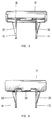
- FIG. 1 illustrates a typical pantograph jack.
- a base 2 supports the jack on a lifting surface.
- a pantograph of four arms provides the lifting and lowering capability.
- Two lower pantograph arms 3 and 4 are pivotally connected in the base 2 and geared to one another to turn synchronously in opposite radial directions.
- Two upper pantograph arms 5 and 6 are pivotally connected in a load rest 10 and geared to one another to turn synchronously in opposite radial directions.
- Joints 7 and 8 connect the lower pantograph arms 3 and 4 to the upper pantograph arms 5 and 6, respectively.
- a drive screw 9 between joints 7 and 8 controls the distance between said joints and thereby the shape and height of the pantograph.
- a load rest 10 supports a load, for example a portion of an automobile or truck, during lifting. The load rest 10 is raised and lowered with respect to the base 2 by controlled operation of the drive screw 9 to deform the pantograph.
- the load rest 10 generally comprises a right leg 13. a left leg 14, a top surface 15, a trough 16 and a ridge 17.
- Each leg has holes 34 to receive pins 11 and 12 to connect onto the upper pantograph arms 5 and 6.
- the top surface 15 is lower than the ridge 17. This feature facilitates location of the load rest 10 in relation to a depending flange of a vehicle (not shown) while the jack is slid under the vehicle in the lowered position.
- the top surface 15 slides under the flange and the ridge 17 abuts against the flange to align the trough 16 under the flange. Then as the jack is raised the flange is located securely in the trough 16.
- the load rest 10 is manufactured by bending a flat steel plate 20 that has been cut in the shape shown in Figure 2.
- Figure 2 shows a number of imaginary folding lines to indicate where the plate is bent during fabrication. Folding lines 21 and 22 delineate the legs 13 and 14 respectively and the section between them. The folding line 23 permits the leg assembly to be folded under the balance of the plate 20.
- the plate 20 is also bent at folding lines 24, 25 and 26 to form the trough 16 and then at folding lines 27 and 28 to form the ridge 17. It is also bent at folding line 29 to form a tab 30 which is folded into slot 31 and into slot 32 as a last step to lock the folded construction into an integral unit.
- the section between the legs 13 and 14 has a rectangular opening 33 to receive the depending trough 16 which tends to further secure the folded parts together.
- the process for manufacture of the load rest is as follows.
- the plate 20 is cut into a two dimensional shape generally shown in Figure 2 including the locking tab 30, the slot 31, the rectangular opening 33, the legs 13 and 14 the trough 16, the ridge 17 and the connecting holes 34 for attaching a load rest to the upper arms 5 and 6 of the pantograph jack.
- the plate 20 may folded differently than as next described depending upon the tocls employed.
- the ridge 17 be formed first by folding the plate downwardly at folding lines 27 and 28; next the trough 16 is formed by folding upwardly at successive right angled folds on lines 25 and 26 and then downwardly at right angles at line 24 to form the flat portion 15.
- the dimples 35 and 36 are formed downwardly at opposite lateral ends of rectangular opening 33 and legs 13 and 14 are bent upwardly at folding lines 21 and 22, respectively. (The dimples are best shown in Figures 4, 5, 6 and 7).
- the leg assembly is folded downwardly at folding line 23 under the trough 16 to fit rectangular opening 33 about the trough 16 and to permit the dimples 35 and 36 to abut it to provide additional support to the laterally projecting ends of the trough 16.
- the tab 30 is connected into slot 31 under flange 32 as illustrated in Figures 6 and 7.
Landscapes
- Life Sciences & Earth Sciences (AREA)
- Engineering & Computer Science (AREA)
- Geology (AREA)
- Mechanical Engineering (AREA)
- Structural Engineering (AREA)
- Vehicle Cleaning, Maintenance, Repair, Refitting, And Outriggers (AREA)
- Auxiliary Methods And Devices For Loading And Unloading (AREA)
Applications Claiming Priority (2)
| Application Number | Priority Date | Filing Date | Title |
|---|---|---|---|
| US551751 | 1995-11-07 | ||
| US08/551,751 US5697598A (en) | 1995-11-07 | 1995-11-07 | One piece load rest |
Publications (3)
| Publication Number | Publication Date |
|---|---|
| EP0774440A2 true EP0774440A2 (de) | 1997-05-21 |
| EP0774440A3 EP0774440A3 (de) | 1999-03-31 |
| EP0774440B1 EP0774440B1 (de) | 2006-02-01 |
Family
ID=24202535
Family Applications (1)
| Application Number | Title | Priority Date | Filing Date |
|---|---|---|---|
| EP96308094A Expired - Lifetime EP0774440B1 (de) | 1995-11-07 | 1996-11-07 | Einteilige Lastaufnahme |
Country Status (3)
| Country | Link |
|---|---|
| US (1) | US5697598A (de) |
| EP (1) | EP0774440B1 (de) |
| DE (1) | DE69635774D1 (de) |
Cited By (1)
| Publication number | Priority date | Publication date | Assignee | Title |
|---|---|---|---|---|
| WO2010056218A1 (en) * | 2008-11-11 | 2010-05-20 | Arikan Kriko Ve Makina Sanayi Ticaret Anonim Sirketi | Load support for a jack, having bended parts |
Families Citing this family (7)
| Publication number | Priority date | Publication date | Assignee | Title |
|---|---|---|---|---|
| US5975497A (en) * | 1998-01-06 | 1999-11-02 | Norco Industries, Inc. | Multipiece trunnion for a scissor type jack |
| TR201600960A2 (tr) * | 2016-01-23 | 2016-06-21 | Arikan Kriko Ve Makina Sanayi Ve Ticaret Anonim Sirketi | Kri̇kolar i̇çi̇n kaldirma başliği |
| US10513422B2 (en) * | 2017-03-24 | 2019-12-24 | Volkswagen Of America, Inc. | Vehicle jack and adapter therefor |
| CN110040648A (zh) * | 2018-01-15 | 2019-07-23 | 福特环球技术公司 | 剪式千斤顶 |
| USD906623S1 (en) * | 2019-07-24 | 2020-12-29 | WeiFeng Liang | Scissor jack |
| USD955084S1 (en) * | 2021-01-26 | 2022-06-14 | Ziwei LI | Cross base scissor jack |
| CN114407731B (zh) * | 2022-01-06 | 2023-06-09 | 杭州申昊科技股份有限公司 | 一种地铁装配式刚性接触网悬挂装置 |
Citations (9)
| Publication number | Priority date | Publication date | Assignee | Title |
|---|---|---|---|---|
| US1701314A (en) | 1927-10-01 | 1929-02-05 | Lawrence G Shook | Jack |
| US4194725A (en) | 1978-01-16 | 1980-03-25 | Firma August Bilstein | Vehicle jack |
| DE2936002A1 (de) | 1979-09-06 | 1981-03-26 | E.A. Storz Gmbh & Co Kg, 78532 Tuttlingen | Wagenheber |
| GB2070560A (en) | 1980-02-26 | 1981-09-09 | Bilstein August | Vehicle lifting jack |
| GB2145392A (en) | 1983-08-20 | 1985-03-27 | Metallifacture Ltd | Vehicle jack |
| US4836502A (en) | 1987-03-21 | 1989-06-06 | Aisin Seiki Kabushiki Kaisha | Pantograph jack |
| US4848733A (en) | 1986-11-04 | 1989-07-18 | Aisin Seiki Kabushiki Kaisha | Vehicle jack assembly |
| US5135201A (en) | 1991-07-01 | 1992-08-04 | Engel Darryl L | Lift cap for a jack |
| US5199688A (en) | 1992-09-14 | 1993-04-06 | Universal Tool & Stamping Company, Inc. | Failure modes for a jack |
Family Cites Families (8)
| Publication number | Priority date | Publication date | Assignee | Title |
|---|---|---|---|---|
| US1534992A (en) * | 1922-08-09 | 1925-04-21 | George Herbert Cuming Butler | Lifting jack |
| GB1551256A (en) * | 1976-12-31 | 1979-08-30 | Lake & Elliot Jacks & Equipmen | Scissors jack |
| FR2571708B1 (fr) * | 1984-10-16 | 1987-12-18 | Renault | Dispositif de levage de vehicule du type " cric " |
| FR2608579B1 (fr) * | 1986-12-23 | 1989-03-17 | Rousseau Jean | Cric de faible encombrement pour vehicules |
| GB8824049D0 (en) * | 1988-10-13 | 1988-11-23 | Metallifacture Ltd | Vehicle jacks |
| DE3921826C1 (de) * | 1989-07-03 | 1990-09-06 | August Bilstein Gmbh & Co Kg, 5828 Ennepetal, De | |
| FR2671065B1 (fr) * | 1990-12-28 | 1993-04-23 | Fabrication Accessoires Automo | Tete de cric ainsi que les crics comportant cette tete. |
| US5449149A (en) * | 1994-05-19 | 1995-09-12 | Ventra Group, Inc. | Pantograph jack |
-
1995
- 1995-11-07 US US08/551,751 patent/US5697598A/en not_active Expired - Lifetime
-
1996
- 1996-11-07 EP EP96308094A patent/EP0774440B1/de not_active Expired - Lifetime
- 1996-11-07 DE DE69635774T patent/DE69635774D1/de not_active Expired - Lifetime
Patent Citations (10)
| Publication number | Priority date | Publication date | Assignee | Title |
|---|---|---|---|---|
| US1701314A (en) | 1927-10-01 | 1929-02-05 | Lawrence G Shook | Jack |
| US4194725A (en) | 1978-01-16 | 1980-03-25 | Firma August Bilstein | Vehicle jack |
| DE3033956A1 (de) | 1978-01-16 | 1982-06-24 | August Bilstein GmbH & Co KG, 5828 Ennepetal | Wagenheber |
| DE2936002A1 (de) | 1979-09-06 | 1981-03-26 | E.A. Storz Gmbh & Co Kg, 78532 Tuttlingen | Wagenheber |
| GB2070560A (en) | 1980-02-26 | 1981-09-09 | Bilstein August | Vehicle lifting jack |
| GB2145392A (en) | 1983-08-20 | 1985-03-27 | Metallifacture Ltd | Vehicle jack |
| US4848733A (en) | 1986-11-04 | 1989-07-18 | Aisin Seiki Kabushiki Kaisha | Vehicle jack assembly |
| US4836502A (en) | 1987-03-21 | 1989-06-06 | Aisin Seiki Kabushiki Kaisha | Pantograph jack |
| US5135201A (en) | 1991-07-01 | 1992-08-04 | Engel Darryl L | Lift cap for a jack |
| US5199688A (en) | 1992-09-14 | 1993-04-06 | Universal Tool & Stamping Company, Inc. | Failure modes for a jack |
Cited By (1)
| Publication number | Priority date | Publication date | Assignee | Title |
|---|---|---|---|---|
| WO2010056218A1 (en) * | 2008-11-11 | 2010-05-20 | Arikan Kriko Ve Makina Sanayi Ticaret Anonim Sirketi | Load support for a jack, having bended parts |
Also Published As
| Publication number | Publication date |
|---|---|
| DE69635774D1 (de) | 2006-04-13 |
| US5697598A (en) | 1997-12-16 |
| EP0774440B1 (de) | 2006-02-01 |
| EP0774440A3 (de) | 1999-03-31 |
Similar Documents
| Publication | Publication Date | Title |
|---|---|---|
| EP0774440B1 (de) | Einteilige Lastaufnahme | |
| JPH0873194A (ja) | 車両用昇降台装置 | |
| US4653728A (en) | Apparatus for operating and transferring manhole cover | |
| EP0151154B1 (de) | Schleppersattel | |
| US5516066A (en) | Load rest for pantograph jack | |
| EP0232836B1 (de) | Spindelwagenheber | |
| US5011118A (en) | Jack | |
| JPH0768039B2 (ja) | ジャッキの改良型リフト・キャップ | |
| EP0773186B1 (de) | Lagerzapfen für den Gebrauch bei einem Scherenwagenheber | |
| WO2022047064A1 (en) | Safety link | |
| CN212954213U (zh) | 一种液压式升降平台 | |
| US5386969A (en) | Plastic load rest for a jack | |
| US2512228A (en) | Automobile frame straightening equipment | |
| US5031476A (en) | Lever locking mechanism | |
| US4203577A (en) | Car jacks | |
| CN2498132Y (zh) | 升降装置支撑台延长机构 | |
| JPS638714Y2 (de) | ||
| CA1072536A (en) | Jacking device | |
| CN1138660C (zh) | 具有插入式心轴的汽车千斤顶 | |
| JPS5854480Y2 (ja) | パンタグラフ型ジヤツキの操作ヘルプ棒 | |
| WO1986005167A1 (en) | Improvements to car jack | |
| JPH0520789Y2 (de) | ||
| CN222863290U (zh) | 一种可自动抵消间隙的负角度限位梯子及其起重机 | |
| JPS6141749Y2 (de) | ||
| CN216785599U (zh) | 顶升组件及升降平台 |
Legal Events
| Date | Code | Title | Description |
|---|---|---|---|
| PUAI | Public reference made under article 153(3) epc to a published international application that has entered the european phase |
Free format text: ORIGINAL CODE: 0009012 |
|
| AK | Designated contracting states |
Kind code of ref document: A2 Designated state(s): DE ES FR GB IT |
|
| PUAL | Search report despatched |
Free format text: ORIGINAL CODE: 0009013 |
|
| AK | Designated contracting states |
Kind code of ref document: A3 Designated state(s): DE ES FR GB IT |
|
| 17P | Request for examination filed |
Effective date: 19990922 |
|
| 17Q | First examination report despatched |
Effective date: 20041215 |
|
| GRAP | Despatch of communication of intention to grant a patent |
Free format text: ORIGINAL CODE: EPIDOSNIGR1 |
|
| GRAS | Grant fee paid |
Free format text: ORIGINAL CODE: EPIDOSNIGR3 |
|
| GRAA | (expected) grant |
Free format text: ORIGINAL CODE: 0009210 |
|
| AK | Designated contracting states |
Kind code of ref document: B1 Designated state(s): DE ES FR GB IT |
|
| PG25 | Lapsed in a contracting state [announced via postgrant information from national office to epo] |
Ref country code: IT Free format text: LAPSE BECAUSE OF FAILURE TO SUBMIT A TRANSLATION OF THE DESCRIPTION OR TO PAY THE FEE WITHIN THE PRE;WARNING: LAPSES OF ITALIAN PATENTS WITH EFFECTIVE DATE BEFORE 2007 MAY HAVE OCCURRED AT ANY TIME BEFORE 2007. THE CORRECT EFFECTIVE DATE MAY BE DIFFERENT FROM THE ONE RECORDED.SCRIBED TIME-LIMIT Effective date: 20060201 |
|
| REG | Reference to a national code |
Ref country code: GB Ref legal event code: FG4D |
|
| REF | Corresponds to: |
Ref document number: 69635774 Country of ref document: DE Date of ref document: 20060413 Kind code of ref document: P |
|
| PG25 | Lapsed in a contracting state [announced via postgrant information from national office to epo] |
Ref country code: DE Free format text: LAPSE BECAUSE OF FAILURE TO SUBMIT A TRANSLATION OF THE DESCRIPTION OR TO PAY THE FEE WITHIN THE PRESCRIBED TIME-LIMIT Effective date: 20060503 |
|
| PG25 | Lapsed in a contracting state [announced via postgrant information from national office to epo] |
Ref country code: ES Free format text: LAPSE BECAUSE OF FAILURE TO SUBMIT A TRANSLATION OF THE DESCRIPTION OR TO PAY THE FEE WITHIN THE PRESCRIBED TIME-LIMIT Effective date: 20060512 |
|
| ET | Fr: translation filed | ||
| PGFP | Annual fee paid to national office [announced via postgrant information from national office to epo] |
Ref country code: FR Payment date: 20061127 Year of fee payment: 11 |
|
| PLBE | No opposition filed within time limit |
Free format text: ORIGINAL CODE: 0009261 |
|
| STAA | Information on the status of an ep patent application or granted ep patent |
Free format text: STATUS: NO OPPOSITION FILED WITHIN TIME LIMIT |
|
| 26N | No opposition filed |
Effective date: 20061103 |
|
| PGFP | Annual fee paid to national office [announced via postgrant information from national office to epo] |
Ref country code: GB Payment date: 20070212 Year of fee payment: 11 |
|
| GBPC | Gb: european patent ceased through non-payment of renewal fee |
Effective date: 20071107 |
|
| REG | Reference to a national code |
Ref country code: FR Ref legal event code: ST Effective date: 20080930 |
|
| PG25 | Lapsed in a contracting state [announced via postgrant information from national office to epo] |
Ref country code: GB Free format text: LAPSE BECAUSE OF NON-PAYMENT OF DUE FEES Effective date: 20071107 |
|
| PG25 | Lapsed in a contracting state [announced via postgrant information from national office to epo] |
Ref country code: FR Free format text: LAPSE BECAUSE OF NON-PAYMENT OF DUE FEES Effective date: 20071130 |