EP0773613B1 - Artikelpositionierer - Google Patents
Artikelpositionierer Download PDFInfo
- Publication number
- EP0773613B1 EP0773613B1 EP96114451A EP96114451A EP0773613B1 EP 0773613 B1 EP0773613 B1 EP 0773613B1 EP 96114451 A EP96114451 A EP 96114451A EP 96114451 A EP96114451 A EP 96114451A EP 0773613 B1 EP0773613 B1 EP 0773613B1
- Authority
- EP
- European Patent Office
- Prior art keywords
- articles
- article
- disposed
- path
- pins
- Prior art date
- Legal status (The legal status is an assumption and is not a legal conclusion. Google has not performed a legal analysis and makes no representation as to the accuracy of the status listed.)
- Expired - Lifetime
Links
- 239000000969 carrier Substances 0.000 claims description 7
- 238000006073 displacement reaction Methods 0.000 claims description 3
- 229920003023 plastic Polymers 0.000 claims description 3
- 239000004033 plastic Substances 0.000 claims description 3
- 238000009413 insulation Methods 0.000 claims description 2
- 230000000630 rising effect Effects 0.000 claims 1
- 230000000712 assembly Effects 0.000 description 2
- 238000000429 assembly Methods 0.000 description 2
- 230000000694 effects Effects 0.000 description 1
- 210000003746 feather Anatomy 0.000 description 1
- 238000000034 method Methods 0.000 description 1
- 238000004806 packaging method and process Methods 0.000 description 1
- 238000012856 packing Methods 0.000 description 1
Images


Classifications
-
- H—ELECTRICITY
- H01—ELECTRIC ELEMENTS
- H01R—ELECTRICALLY-CONDUCTIVE CONNECTIONS; STRUCTURAL ASSOCIATIONS OF A PLURALITY OF MUTUALLY-INSULATED ELECTRICAL CONNECTING ELEMENTS; COUPLING DEVICES; CURRENT COLLECTORS
- H01R43/00—Apparatus or processes specially adapted for manufacturing, assembling, maintaining, or repairing of line connectors or current collectors or for joining electric conductors
- H01R43/01—Apparatus or processes specially adapted for manufacturing, assembling, maintaining, or repairing of line connectors or current collectors or for joining electric conductors for connecting unstripped conductors to contact members having insulation cutting edges
-
- H—ELECTRICITY
- H01—ELECTRIC ELEMENTS
- H01R—ELECTRICALLY-CONDUCTIVE CONNECTIONS; STRUCTURAL ASSOCIATIONS OF A PLURALITY OF MUTUALLY-INSULATED ELECTRICAL CONNECTING ELEMENTS; COUPLING DEVICES; CURRENT COLLECTORS
- H01R43/00—Apparatus or processes specially adapted for manufacturing, assembling, maintaining, or repairing of line connectors or current collectors or for joining electric conductors
- H01R43/28—Apparatus or processes specially adapted for manufacturing, assembling, maintaining, or repairing of line connectors or current collectors or for joining electric conductors for wire processing before connecting to contact members, not provided for in groups H01R43/02 - H01R43/26
Definitions
- the invention relates to a device for the positioned method of using Plugs, especially equipped with insulation displacement contact elements Housings, the so-called articles, to a two-lane article feed a cable assembly machine, especially for article carriers for a Row of articles arranged in a row.
- the invention has for its object to provide a transport device with which a precise positioning of the articles in two lanes of an article feed to a cable assembly machine or to associated article carriers is made possible in parallel with one another, so that a front-edge alignment of the articles on both lanes for the simultaneous contacting of both cable ends is ensured.
- the device according to the invention should also make it possible to move articles from article feeds, the web of which is equipped with a turning device, in such a way that the front edges of the articles are aligned identically on both sides when they are delivered to the contacting machine.
- the device of the invention is characterized by a movable on a rail by means of a drive Carriage with a carrier device, the article on both sides in both Paths of the article feed with laterally retractable and extendable pins, bolts or the like.
- Driver elements detected.
- the linear transport is now carried out with the slide the registered articles of both tracks simultaneously and in the same Position to the cable assembly machine or the article carriers made and the pulling effect is brought about by moving the driving pins together again and thus out of engagement with the article chambers be pulled out.
- the carriage can then be unloaded back to the starting position drive back.
- This is an extremely accurate position working moving device has been created that is short and compact, is technically very simple and a flush movement-identical Transport of articles on two lanes guaranteed.
- the driver elements are preferably adjustable in the transport direction arranged in the driver device in order to adapt to different articles Pole numbers or to be able to make different articles.
- a parcel pusher for parcels Moving a number of in the one path of the article feed Articles in a predetermined alignment position to the articles of the second web, preferably identical to the leading edges.
- the parcel slide is particularly useful where with a turning device in the second lane of article feeding is being worked on since it is now possible to shift the row of articles in the first article rail in such a way that a leading edge identical alignment to the turned Articles of the second track is given, so that those entering the article chambers Driver pins of the driver device only the fine centering for the subsequent moving.
- the pencils are advantageously conically stepped for this purpose.
- a support bar arranged the space to the cable assembly machine bridged, with the rail for the movable carriage is attached by a toothed belt drive is driven.
- this consists of a toothed pulley driven by a drive cylinder and deflection rollers, over which a toothed belt is guided, which by means of a clamping device Sled is attached.
- a tensioning device for the toothed belt be provided.
- the driver device preferably consists of one with the carriage firmly connected base plate, the two laterally displaceable, in Holds guide recesses arranged parallel to each other, the one on the side of the first track with a holding plate with pins and their second with a similar holding plate on the side of the second track Pins for engaging in chambers of articles of both tracks of the Article feeder is connected.
- the spreader is advantageous provided by an arranged on the driver device Rotary cylinder, on the axis of which a tab is attached, on both of them Each end carries a roller, each in a transverse groove of the associated Slider engages in such a way that when the rotary cylinder is turned, the two sliders with their holding plates and pins arranged thereon are spread outwards against each other or in the opposite direction be driven back again.
- the packet slide is made from a rotary actuator, on the axis of which stands high Tab with a fork recess is arranged at its free end in the a roller attached to a finger on one end for movement engages, the free end of the finger being provided with a latch is a number in the direction of transport in front of the driver device of articles in the associated article guide (first lane) to moved in packets.
- the pawl is preferably spring-loaded and provided with an inclined contact surface in order to avoid running over the To enable the jack through the articles conveyed in the article rail.
- the Path of movement of the tab is preferably by stops arranged on both sides in the form of plastic rolls, limited.
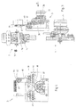
- the entire item positioner consists of the three main assemblies of the moving device 1, driver device 2 and packaging slide 3. Below are the three main assemblies in detail based on the associated Drawing described.
- the traversing device 1 is a continuation of a two-lane article feed between the end of the two article rails and one not shown Cable assembly machine, especially its article carriers arranged in the center and serves for the positioned movement of articles from the Article feed to the cable assembly machine. It consists of an under a support bar 4 with a rail 5 mounted drive cylinder 6 with toothed belt pulley 8 fastened on its drive shaft 7 and pulleys 9, 10, 11 at both ends of the support bar 4 to the one Toothed belt 12 is guided.
- a carriage 13 On the rail 5, a carriage 13 is arranged movable, which with the Drive via a clamping device 14 is firmly connected in that this holds the timing belt 12.
- a tensioning device 15 acts on the toothed belt 12, whose linear movement transmitted to the carriage 13 by Buffer is limited. The effective diameter of the toothed belt pulley is adjusted so that the angle of rotation of the drive cylinder Desired stroke for the reciprocation of the carriage 13 results.
- a base plate 16 is located on the carriage above the clamping device 14 attached, the two laterally displaceable, in guide recesses 17, 18th the base plate 16 holds sliders 19, 20 arranged parallel to one another, wherein the one slide 19 with a holding plate 21 with pins 22, 23 and other slide 20 with a holding plate 24 with pins 25, 26 on the opposite Side is connected.
- the slides 19, 20 are off-center arranged grooves 27, 28, engage in the rollers 29, 30 from above, the at the two ends of an obliquely arranged tab 31 of the rotary drive are arranged.
- the rotary drive for spreading and retracting the on the Holding plates 21 and 24 arranged pins 22, 23 and 25, 26 consists of a rotary cylinder 32, the drive shaft 33 is firmly connected to the tab 28 is.
- the package pusher 3 detects those fed to the article rail of the first web Article 34 and serves to make these leading edges flush with the articles 35 align the second path, in which a turning plate, not shown is arranged.
- the package slide 3 consists of a Swivel drive 36, on its drive shaft 37 a raised tab 38 is arranged with a fork recess 39 at its free end, in the a roller 41 attached to a finger 40 at one end, for example in the form of a ball bearing, engages to take movement.
- the other, free end of the finger 40 is provided with a pawl 42 which in Transport direction in front of the driver device a number of in the associated Article guidance (first lane) of article 34 to be packaged Moving detected.
- the pawl 42 is loaded by a spring 43 and with an inclined contact surface 44 in order to pass over the pawl 42 through the article 34 promoted in the article rail.
- the Path of movement of the tab 38 is by stops arranged in on both sides in Form of plastic rollers 45, 46 limited.
- article 34, 35 linearly fed to the traversing device 1 one behind the other Article 34 located on the first path in packets through the packet slide 3 in a front-flush alignment to those on the web 2 by means of a turning device Article 35 are moved.
- To this end 4 engages behind a series of articles and moves it by means of the drive 37 from that in Fig. 4 of the drawing right position to the left position, in which the flush alignment to the Article of the second lane is given.
- the movement is through the stops 45, 46 controlled.
- the holding plates 21 and 24 are now included their pins, 22, 23, 25, 26 spread and into the coaxial chambers of the Articles 34 and 35 or the covered packages of articles are introduced. It takes place then the movement of the entire carriage 13 with the two-sided Article packages according to the work of the drive cylinder 7 to article carriers the cable assembly machine instead. After positioning in the The pins 22, 23, 25, 26 with their holding plates 21, 24 become article carriers moved back and the article packages for further transport to the contacting station the cable contact machine released. The carriage 13 travels back to the starting position shown in Fig. 1 of the drawing to again Include packages from Articles 34, 35.
Landscapes
- Engineering & Computer Science (AREA)
- Manufacturing & Machinery (AREA)
- Manufacturing Of Electrical Connectors (AREA)
- Seal Device For Vehicle (AREA)
- Vehicle Body Suspensions (AREA)
- Attitude Control For Articles On Conveyors (AREA)
- Control Of Conveyors (AREA)
Description
- Fig. 1
- eine Draufsicht auf eine Verfahreinrichtung, teilweise mit Schnitt,
- Fig. 2
- die Verfahreinrichtung der Fig. 1 in einer Vorderansicht,
- Fig. 3
- die Verfahreinrichtung der Figuren 1 und 2 in einer Seitenansicht, teilweise im Schnitt, mit Paketierschieber und
- Fig. 4
- den Paketierschieber in der Ansicht A der Fig. 3.
- 1
- Verfahreinrichtung
- 2
- Mitnehmereinrichtung
- 3
- Paketierschieber
- 4
- Tragleiste
- 5
- Schiene
- 6
- Antriebszylinder
- 7
- Antriebsachse
- 8
- Zahnriemenscheibe
- 9
- Umlenkrolle
- 10
- Umlenkrolle
- 11
- Umlenkrolle
- 12
- Zahnriemen
- 13
- Schlitten
- 14
- Klemmeinrichtung
- 15
- Spanneinrichtung
- 16
- Grundplatte
- 17
- Führungsausnehmung
- 18
- Führungsausnehmung
- 19
- Schieber
- 20
- Schieber
- 21
- Halteplatte
- 22
- Stift
- 23
- Stift
- 24
- Halteplatte
- 25
- Stift
- 26
- Stift
- 27
- Nute
- 28
- Nute
- 29
- Rolle
- 30
- Rolle
- 31
- Lasche
- 32
- Drehzylinder
- 33
- Achse
- 34
- Artikel
- 35
- Artikel
- 36
- Schwenkantrieb
- 37
- Achse
- 38
- Lasche
- 39
- Gabelausnehmung
- 40
- Finger
- 41
- Rolle
- 42
- Klinke
- 43
- Feder
- 44
- Anlauffläche
- 45
- Anschlag
- 46
- Anschlag
Claims (11)
- Vorrichtung zum positionierten Verfahren von mit Steckern, insbesondere mit Schneidklemmkontaktelementen, ausgerüsteten Gehäusen, den sogenannten Artikeln, einer zweibahnigen Artikelzuführung zu einer Kabelkonfektioniermaschine, insbesondere zu Artikelträgern für eine Reihe linear hintereinander angeordneter Artikel,
gekennzeichnet durch
einen auf einer Schiene (5) mittels eines Antriebs (7) verfahrbaren Schlitten (13) mit einer Mitnehmereinrichtung (2), die beidseitig die Artikel (34, 35) in beiden Bahnen der Artikelzuführung mit seitlich ein- und ausfahrbaren Stiften (22, 23; 25, 26), Bolzen oder dgl. Mitnehmerelementen erfaßt. - Vorrichtung nach Anspruch 1, dadurch gekennzeichnet, daß die Mitnehmerelemente (Stifte 22, 23; 25, 26) in Transportrichtung verstellbar in der Mitnehmereinrichtung (2) angeordnet sind.
- Vorrichtung nach Anspruch 1 und 2, dadurch gekennzeichnet, daß in Transportrichtung vor der Mitnehmereinrichtung (2) ein Paketierschieber (3) zum paketweisen Verschieben einer Anzahl von in der einen Bahn der Artikelzuführung befindlichen Artikeln (34) in eine vorbestimmte Ausrichtposition zu den Artikeln (35) der zweiten Bahn, vorzugsweise vorderkantenidentisch, angeordnet ist.
- Vorrichtung nach einem der Ansprüche 1 bis 3, dadurch gekennzeichnet, daß die Verfahreinrichtung (1) eine zwischen den beiden Bahnen der Artikelzuführung angeordnete Tragleiste (4) aufweist, die den Raum zur Kabelkonfektioniermaschine überbrückt, wobei auf der Tragleiste (4) eine Schiene (5) für den verfahrbaren Schlitten (13) befestigt ist, der durch einen Zahnriemenantrieb (7) angetrieben ist.
- Vorrichtung nach Anspruch 4, dadurch gekennzeichnet, daß der Zahnriemenantrieb aus einer von einem Antriebszylinder (7) angetriebenen Zahnscheibe (8) sowie Umlenkrollen (9, 10, 11) und einem darüber geführten Zahnriemen (12) besteht, der mittels einer Klemmeinrichtung (14) am Schlitten (13) befestigt ist.
- Vorrichtung nach Anspruch 4 und 5, gekennzeichnet durch eine Spanneinrichtung (15) für den Zahnriemen (12).
- Vorrichtung nach einem der Ansprüche 1 bis 6, dadurch gekennzeichnet, daß die Mitnehmereinrichtung (2) aus einer mit dem Schlitten (13) fest verbundenen Grundplatte (16) besteht, die zwei seitlich verschiebbare, in Führungsausnehmungen (17, 18) parallel zueinander angeordnete Schieber (19, 20) hält, deren einer auf der Seite der ersten Bahn mit einer Halteplatte (21) mit Stiften (22, 23) und deren zweiter auf der Seite der zweiten Bahn mit einer gleichartigen Halteplatte (24) mit Stiften (25, 26) für den Eingriff in Kammern der Artikel (34, 35) beider Bahnen der Artikelzuführung verbunden ist.
- Vorrichtung nach Anspruch 7, gekennzeichnet durch eine aus einem auf der Mitnehmereinrichtung (2) angeordneten Drehzylinder (32) bestehenden Spreizeinrichtung, an dessen Achse (33) eine Lasche (31) befestigt ist, die an ihren beiden Enden je eine Rolle (29, 30) trägt, welche jeweils in eine Quernut (27, 28) des zugehörigen Schiebers (19, 20) derart eingreift, daß bei einem Verdrehen des Drehzylinders (32) die beiden Schieber (19, 20) mit ihren daran angeordneten Halteplatten (21, 24) und Stiften (22, 23, 25, 26) gegeneinander nach außen spreizbar oder in Umkehrichtung zurückfahrbar sind.
- Vorrichtung nach einem der Ansprüche 3 bis 8, dadurch gekennzeichnet, daß der Paketierschieber (3) aus einem Schwenkantrieb (36) besteht, auf dessen Achse (37) eine hochstehende Lasche (38) mit einer Gabelausnehmung (39) an ihrem freien Enden angeordnet ist, in die eine auf einem Finger (40) an dem einen Ende befestigte Rolle (41) zur Bewegungsmitnahme eingreift, wobei das freie Ende des Fingers (40) mit einer Klinke (42) versehen ist, die in Transportrichtung vor der Mitnehmereinrichtung (2) eine Anzahl von in der zugehörigen Artikelzuführung (erste Bahn) befindlichen Artikel (34) zum paketweisen Verschieben erfaßt.
- Vorrichtung nach Anspruch 9, dadurch gekennzeichnet, daß die Klinke (42) federbelastet ist und mit einer schrägen Anlauffläche (44) versehen ist.
- Vorrichtung nach Anspruch 9 und 10, dadurch gekennzeichnet, daß der Bewegungsweg der Lasche (38) durch beiderseitig angeordnete Anschläge (45, 46), vorzugsweise in Form von Kunststoffrollen begrenzt ist.
Applications Claiming Priority (2)
| Application Number | Priority Date | Filing Date | Title |
|---|---|---|---|
| DE29517601U DE29517601U1 (de) | 1995-11-07 | 1995-11-07 | Artikelpositionierer |
| DE29517601U | 1995-11-07 |
Publications (3)
| Publication Number | Publication Date |
|---|---|
| EP0773613A2 EP0773613A2 (de) | 1997-05-14 |
| EP0773613A3 EP0773613A3 (de) | 1998-09-30 |
| EP0773613B1 true EP0773613B1 (de) | 2001-11-07 |
Family
ID=8015090
Family Applications (1)
| Application Number | Title | Priority Date | Filing Date |
|---|---|---|---|
| EP96114451A Expired - Lifetime EP0773613B1 (de) | 1995-11-07 | 1996-09-10 | Artikelpositionierer |
Country Status (2)
| Country | Link |
|---|---|
| EP (1) | EP0773613B1 (de) |
| DE (2) | DE29517601U1 (de) |
Family Cites Families (7)
| Publication number | Priority date | Publication date | Assignee | Title |
|---|---|---|---|---|
| CA1167626A (en) * | 1980-06-09 | 1984-05-22 | Daniel B. Grubb | Apparatus for, and a method of, serially manufacturing electrical harness assemblies |
| US4411062A (en) * | 1981-01-21 | 1983-10-25 | Amp Incorporated | Apparatus and method for terminating ribbon cable |
| US4856187A (en) * | 1988-03-31 | 1989-08-15 | Artos Engineering Company | Apparatus and methods for making terminated wire segments |
| US4907324A (en) * | 1988-09-07 | 1990-03-13 | Molex Incorporated | Connector termination apparatus and method |
| US4903399A (en) * | 1989-02-28 | 1990-02-27 | American Telephone And Telegraph Company | Apparatus for attaching a connector |
| DE3939774C1 (de) * | 1989-12-01 | 1991-02-07 | Stocko Metallwarenfabriken Henkels Und Sohn Gmbh & Co, 5600 Wuppertal, De | |
| US5142771A (en) * | 1991-09-18 | 1992-09-01 | Amp Incorporated | Spring powered feeder for feeding electrical connector from a tube magazine |
-
1995
- 1995-11-07 DE DE29517601U patent/DE29517601U1/de not_active Expired - Lifetime
-
1996
- 1996-09-10 DE DE59608132T patent/DE59608132D1/de not_active Expired - Fee Related
- 1996-09-10 EP EP96114451A patent/EP0773613B1/de not_active Expired - Lifetime
Also Published As
| Publication number | Publication date |
|---|---|
| DE59608132D1 (de) | 2001-12-13 |
| EP0773613A3 (de) | 1998-09-30 |
| EP0773613A2 (de) | 1997-05-14 |
| DE29517601U1 (de) | 1996-01-04 |
Similar Documents
| Publication | Publication Date | Title |
|---|---|---|
| EP1992579B1 (de) | Vorrichtung zum Verschieben von Gebinden gegenüber einer Transportbahn | |
| EP1123884A1 (de) | Vorrichtung zum Ablenken von Gegenständen, insbesondere Behältern, von einer Bewegungsbahn | |
| DE4036214C2 (de) | ||
| EP0727370B1 (de) | Förderanlage | |
| DE3126808C2 (de) | ||
| WO1998049083A2 (de) | Vorrichtung zur übergabe von stückgut zwischen zwei förderern | |
| DE102012103557B4 (de) | Werkstückträger, Mitnehmersystem und Werkstücktransportvorrichtung | |
| AT400340B (de) | Einrichtung zum verlegen von schwellen | |
| EP0504442A1 (de) | Vorrichtung zum Zuführen von Werkstücken zu einer Bearbeitungsmaschine | |
| CH679563A5 (de) | ||
| DD236503A1 (de) | Foerdereinrichtung zur wahlweisen 180 hoch grad-drehung von buechern oder buchblocks | |
| DE2940014C2 (de) | Vorrichtung zum Quertransport | |
| EP0773613A2 (de) | Artikelpositionierer | |
| DE2516500C2 (de) | ||
| DE3717867C2 (de) | ||
| EP0691296A1 (de) | Beschickungseinrichtung für Plattenaufteilsägen | |
| DE4314600B4 (de) | Vorrichtung zur lageweisen Stapelung von gruppierten Gegenständen | |
| DE4205197C2 (de) | Vorrichtung zum Einfüllen von Füllgut in eine Hülle, insbesondere einen Briefumschlag | |
| EP1726552A1 (de) | Einrichtung zum Sammeln von Druckprodukten | |
| DE1932692A1 (de) | Vorrichtung zum lagenweisen UEbereinanderstapeln von Walzprofilen | |
| DE102021119844B3 (de) | Fördersystem und Verfahren zum Fördern von Werkstückträgern | |
| DE2247945C3 (de) | Vorrichtung zum Entladen von Paletten | |
| DE3203035C2 (de) | Vorrichtung zum seitlichen Übergeben von auf Trägern einer umlaufenden Fördereinrichtung liegenden folienartigen Gegenständen | |
| DE3539762A1 (de) | Verfahren und vorrichtung zur bildung von lagen vorbestimmter breite aus mehreren hoelzern, vorzugsweise schnitthoelzern | |
| DE2521465A1 (de) | Transportwalzenbahn |
Legal Events
| Date | Code | Title | Description |
|---|---|---|---|
| PUAI | Public reference made under article 153(3) epc to a published international application that has entered the european phase |
Free format text: ORIGINAL CODE: 0009012 |
|
| AK | Designated contracting states |
Kind code of ref document: A2 Designated state(s): BE DE FR GB IT NL |
|
| 17P | Request for examination filed |
Effective date: 19980528 |
|
| PUAL | Search report despatched |
Free format text: ORIGINAL CODE: 0009013 |
|
| AK | Designated contracting states |
Kind code of ref document: A3 Designated state(s): BE DE FR GB IT NL |
|
| GRAG | Despatch of communication of intention to grant |
Free format text: ORIGINAL CODE: EPIDOS AGRA |
|
| GRAG | Despatch of communication of intention to grant |
Free format text: ORIGINAL CODE: EPIDOS AGRA |
|
| GRAH | Despatch of communication of intention to grant a patent |
Free format text: ORIGINAL CODE: EPIDOS IGRA |
|
| 17Q | First examination report despatched |
Effective date: 20010330 |
|
| RAP1 | Party data changed (applicant data changed or rights of an application transferred) |
Owner name: STOCKO CONTACT GMBH & CO. KG |
|
| GRAH | Despatch of communication of intention to grant a patent |
Free format text: ORIGINAL CODE: EPIDOS IGRA |
|
| GRAA | (expected) grant |
Free format text: ORIGINAL CODE: 0009210 |
|
| AK | Designated contracting states |
Kind code of ref document: B1 Designated state(s): BE DE FR GB IT NL |
|
| REF | Corresponds to: |
Ref document number: 59608132 Country of ref document: DE Date of ref document: 20011213 |
|
| REG | Reference to a national code |
Ref country code: GB Ref legal event code: IF02 |
|
| GBT | Gb: translation of ep patent filed (gb section 77(6)(a)/1977) |
Effective date: 20020110 |
|
| ET | Fr: translation filed | ||
| PG25 | Lapsed in a contracting state [announced via postgrant information from national office to epo] |
Ref country code: GB Free format text: LAPSE BECAUSE OF NON-PAYMENT OF DUE FEES Effective date: 20020910 |
|
| PLBE | No opposition filed within time limit |
Free format text: ORIGINAL CODE: 0009261 |
|
| STAA | Information on the status of an ep patent application or granted ep patent |
Free format text: STATUS: NO OPPOSITION FILED WITHIN TIME LIMIT |
|
| PG25 | Lapsed in a contracting state [announced via postgrant information from national office to epo] |
Ref country code: BE Free format text: LAPSE BECAUSE OF NON-PAYMENT OF DUE FEES Effective date: 20020930 |
|
| 26N | No opposition filed | ||
| BERE | Be: lapsed |
Owner name: *STOCKO CONTACT G.M.B.H. & CO. K.G. Effective date: 20020930 |
|
| PG25 | Lapsed in a contracting state [announced via postgrant information from national office to epo] |
Ref country code: NL Free format text: LAPSE BECAUSE OF NON-PAYMENT OF DUE FEES Effective date: 20030401 Ref country code: DE Free format text: LAPSE BECAUSE OF NON-PAYMENT OF DUE FEES Effective date: 20030401 |
|
| GBPC | Gb: european patent ceased through non-payment of renewal fee |
Effective date: 20020910 |
|
| PG25 | Lapsed in a contracting state [announced via postgrant information from national office to epo] |
Ref country code: FR Free format text: LAPSE BECAUSE OF NON-PAYMENT OF DUE FEES Effective date: 20030603 |
|
| REG | Reference to a national code |
Ref country code: FR Ref legal event code: ST |
|
| PG25 | Lapsed in a contracting state [announced via postgrant information from national office to epo] |
Ref country code: IT Free format text: LAPSE BECAUSE OF NON-PAYMENT OF DUE FEES;WARNING: LAPSES OF ITALIAN PATENTS WITH EFFECTIVE DATE BEFORE 2007 MAY HAVE OCCURRED AT ANY TIME BEFORE 2007. THE CORRECT EFFECTIVE DATE MAY BE DIFFERENT FROM THE ONE RECORDED. Effective date: 20050910 |