EP0773125B1 - Spiegelbaueinheit - Google Patents
Spiegelbaueinheit Download PDFInfo
- Publication number
- EP0773125B1 EP0773125B1 EP96117309A EP96117309A EP0773125B1 EP 0773125 B1 EP0773125 B1 EP 0773125B1 EP 96117309 A EP96117309 A EP 96117309A EP 96117309 A EP96117309 A EP 96117309A EP 0773125 B1 EP0773125 B1 EP 0773125B1
- Authority
- EP
- European Patent Office
- Prior art keywords
- mirror
- housing
- cover
- unit according
- mirror unit
- Prior art date
- Legal status (The legal status is an assumption and is not a legal conclusion. Google has not performed a legal analysis and makes no representation as to the accuracy of the status listed.)
- Expired - Lifetime
Links
- 230000000087 stabilizing effect Effects 0.000 claims description 4
- 239000002991 molded plastic Substances 0.000 claims 1
- 238000003466 welding Methods 0.000 description 10
- 238000002347 injection Methods 0.000 description 2
- 239000007924 injection Substances 0.000 description 2
- 238000009434 installation Methods 0.000 description 2
- 238000000034 method Methods 0.000 description 2
- 238000010137 moulding (plastic) Methods 0.000 description 2
- 206010041662 Splinter Diseases 0.000 description 1
- 230000000712 assembly Effects 0.000 description 1
- 238000000429 assembly Methods 0.000 description 1
- 238000010276 construction Methods 0.000 description 1
- 238000011161 development Methods 0.000 description 1
- 230000018109 developmental process Effects 0.000 description 1
- 238000006073 displacement reaction Methods 0.000 description 1
- 239000011888 foil Substances 0.000 description 1
- 230000004313 glare Effects 0.000 description 1
- 239000011521 glass Substances 0.000 description 1
- 239000002184 metal Substances 0.000 description 1
- 239000011241 protective layer Substances 0.000 description 1
- 238000009877 rendering Methods 0.000 description 1
- 125000006850 spacer group Chemical group 0.000 description 1
Images

Classifications
-
- B—PERFORMING OPERATIONS; TRANSPORTING
- B60—VEHICLES IN GENERAL
- B60J—WINDOWS, WINDSCREENS, NON-FIXED ROOFS, DOORS, OR SIMILAR DEVICES FOR VEHICLES; REMOVABLE EXTERNAL PROTECTIVE COVERINGS SPECIALLY ADAPTED FOR VEHICLES
- B60J3/00—Antiglare equipment associated with windows or windscreens; Sun visors for vehicles
- B60J3/02—Antiglare equipment associated with windows or windscreens; Sun visors for vehicles adjustable in position
- B60J3/0204—Sun visors
- B60J3/0278—Sun visors structure of the body
- B60J3/0282—Sun visors structure of the body specially adapted for a courtesy mirror
Definitions
- the invention relates to a mirror assembly for vehicle sun visors.
- Vehicle sun visors are used to enhance and increase comfort increasingly equipped with mirrors.
- the so far Mirror assemblies in use are rectangular Mirror equipped, apparently in line with the rectangular shape the vehicle sun visors, but probably not for functional reasons.
- a conventional mirror assembly is e.g. B. shown in DE 41 02 517 A1.
- the present invention has for its object a mirror assembly for vehicle sun visors, with one of the human head-shaped mirror and a mirror cover that can perform its function in the smallest space.
- a cost-effective one that fully meets aesthetic requirements Desired design form.
- the invention therefore relates to a mirror assembly for vehicle sun visors with a flat oval or elliptical housing, one Casing base that runs all the way from a perpendicular to this Collar is surrounded and has a circular opening in one longitudinal end, a round mirror covering the opening from the inside of the housing, whose diameter is larger than that of the opening and a flat Lid that is pear-shaped or teardrop-shaped and inside the housing articulated so pivotably on an end region of the short housing axis is that it covers the mirror in a first end position and in is able to essentially expose the mirror in a second end position.
- the pivoted mirror cover is u. a. also derived and created due to the biodesign and has the advantage Fulfilling their function in the smallest space is therefore a sensible option and good alternative to the previously known systems.
- a mirror adapted to today's biodesign, is found with the design of a circular mirror and thus an optimal use of space as well as a new rotatable mirror cover. This interpretation or conception of the type of cover offers compared to one Sliding cover the advantage of being able to be designed to save space, what z. B. is quite advantageous with smaller apertures.
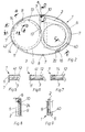
- the housing 1 is a plastic molding and due to the construction and Conception of oval or elliptical shape. Also for reasons of stability a circumferential collar 6 is attached with arranged, raised webs 7 each opposite the center of the oval or ellipse, which can later be used for mirror welding. The one on the narrow side of the housing attached opposite webs 7 are with a through slot 8 provided that for fixing a to be assembled at the end Stabilizing element 4 is used.
- a bearing journal 10 is located locally on the inner wall of the housing base 9 molded with appropriate undercut.
- the housing base 9 has local a round opening 12 with two semicircular bulges 13.
- On the outside of the housing base 9 are local Welding zones 5 attached, for an ultrasonic welding a Serve label clip 5.
- On the inside of the circumferential collar 6 is for a slight latching of the cover 2 in the open position increases 16 intended.
- An additional web 40 is located on the inside of the collar 6 attached, which additionally guide the cover 2 in the open end position should and keeps at a distance, so that no tilting or tipping is caused.
- the Tiketklammer 5 is a plastic molding and the round or elliptical Mask or housing contour adapted. Are provided on the Fastening bridge 17 welding zones 18, which conform and congruent are with the welding zones 15 on the housing 1.
- the cover 2 serving as a mirror cover is a plastic injection molded part about pear-like or teardrop-shaped shape.
- a circular recess 21 is provided in the cover 2. This is said to be one Avoid extensive contact with the mirror 3 and better sliding cause.
- a resilient latching tongue 22 is provided locally, which covers the cover 2 should fix in the open and closed position.
- a receiving hole 24 is provided in the tapered contour area 23 of the cover 2, and serves as Bearing point (fulcrum) for the lid 2. To operate the lid 2 is attached to this an operating handle 25.
- the mirror 3 has a round shape and is preferably made of glass commercial quality.
- the mirror 3 can also from z. B. plastic or metal.
- the back of the mirror 3 is for a possibly required Splinter binding provided with an elastic protective layer.
- the stabilizing element 4 is a U-shaped plastic injection molded part. On the ends of the U-profile are integrated in the U-channel webs 28, which for a Plug assembly serve. On the underside of the U-profile is an anti-shift device of the mirror 3 serving circular segment 30 molded.
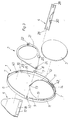
- the label clip 5 is first fed to the housing base 9 and by means of ultrasonic welding at the designated welding zones 15 and 18 permanently connected. Then the Cover 2, in such a way that the receiving hole 24 the bearing pin 10th is fed and clipped on. The undercut on the journal 10 prevents loosening.
- the lid 2 is now in accordance with FIG. 2 in the list pivoted in, the resilient locking tongue 22 on the elevation 16 snaps.
- the semicircular increase or actuation handle 25 is now in one of the semicircular bulges 13 and protrudes from the housing base 9 for the possibility of actuation.
- the mirror 3 can be mounted as the penultimate part. For this purpose, the mirror 3 inserted approximately in the middle of the housing, to the left as shown in FIG. 2 pushed, the mirror 3 brought by the webs 14 to height distance and is secured by the webs 11 against falling out.
- the stabilizing element 4 is mounted as the last part.
- the webs 28 attached in the U channel are in the Through slot 8 of the two webs 7 pressed into self-locking.
- the Circle segment 30 attached to the underside of the U-profile causes this secures the mirror 3 against displacement and the underside of the U-profile 4 serves as a mirror support as shown in Fig. 2.
- the lid 2 is z. B. from the "lineup" position by means of Actuating handle 25 via the mirror 3 corresponding to that shown
- the direction of the arrow is pivoted, the cover 2 is in the free channel 41 out until the actuating handle 25 into the intended semicircular bulge 13 is immersed.
- slight locking of the cover 2 is effected by a recess 42 with the Locking tongue 22 on one of the spacers 14.
- the mirror 3 is now covered.
- the opening procedure is the same as that of closing.
- the lid 2 In the position "Open” the lid 2 is also fixed by the locking tongue 22 in Connection with the elevation 16.
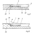
- Fig. 12 For vehicle sun visors that do not allow mirror welding, as shown in Fig. 12 provided that the housing circumferentially one trained flange 35. This is used for all-round HF welding 36 with the film 37, being welded in one operation and by means of the foil 37 is separated from a cutting edge located in the electrode. The inner film field 38 is then torn out, corresponding to the Representation in Fig. 12.
Landscapes
- Engineering & Computer Science (AREA)
- Mechanical Engineering (AREA)
- Rear-View Mirror Devices That Are Mounted On The Exterior Of The Vehicle (AREA)
- Mirrors, Picture Frames, Photograph Stands, And Related Fastening Devices (AREA)
- Optical Elements Other Than Lenses (AREA)
Description
- Fig. 1
- eine Draufsicht auf die Spiegelbaueinheit,
- Fig. 2
- eine Rückansicht der Spiegelbaueinheit,
- Fig. 3
- eine perspektivische Explosivdarstellung der Spiegelbaueinheit
- Fig. 4
- einen Schnitt F - F nach Fig. 1,
- Fig. 5
- einen Schnitt A - A nach Fig. 2,
- Fig. 6
- einen Schnitt B - B nach Fig. 2,
- Fig. 7
- einen Schnitt C - C nach Fig. 2,
- Fig. 8
- einen Schnitt D - D nach Fig. 2,
- Fig. 9
- einen Schnitt E - E nach Fig. 2,
- Fig. 10
- eine Fahrzeugsonnenblende mit Spiegelbaueinheit,
- Fig. 11
- ein erstes und
- Fig. 12
- ein zweites Einbaubeispiel der Spiegelbaueinheit etwa folgend G - G in Fig. 10.
Claims (7)
- Spiegelbaueinheit für Fahrzeugsonnenblenden miteinem flachen oval- oder ellipsenförmigen Gehäuse (1),einem Gehäuseboden (9), der umlaufend von einem zu diesem senkrecht ausgerichteten Kragen (6) umgeben ist und eine kreisrunde Öffnung (12) an einem Längsende aufweist,einem die Öffnung (12) vom Gehäuseinnern her abdeckenden runden Spiegel (3), dessen Durchmesser größer als der der Öffnung (12) ist undeinem flachen Deckel (2), der birnen- bzw. tropfenförmig gestaltet und innerhalb des Gehäuses (1) an einem Endbereich der kurzen Gehäuseachse derart schwenkbeweglich angelenkt ist, daß er in einer ersten Endstellung den Spiegel (3) abzudecken und in einer zweiten Endstellung den Spiegel (3) im wesentlichen freizulegen vermag.
- Spiegelbaueinheit nach Anspruch 1, dadurch gekennzeichnet, daß der Deckel (2) zwischen dem Gehäuseboden (9) und dem Spiegel (3) verschwenkbar gelagert ist und daß der Deckel (2) in seiner den Spiegel (3) freilegenden Position den Spiegel (3) noch geringfügig abdeckt.
- Spiegelbaueinheit nach Anspruch 1 oder 2, dadurch gekennzeichnet, daß der Kragen (6) am der kreisrunden Öffnung (12) benachbarten Endbereich des Gehäuses (1) obere und untere Stegsegmente (11, 14) aufweist, zwischen denen der Spiegel 3 aufgenommen ist und daß das Gehäuse (1) ein sich längs der kurzen Gehäuseachse erstreckendes Stabilisierungselement (4) mit einem Verschiebesicherungs-Element (30) für den Spiegel (3) trägt.
- Spiegelbaueinheit nach wenigstens einem der Ansprüche 1 - 3, dadurch gekennzeichnet, daß der Deckel (2) an einem Randbereich eine Federzunge (22) aufweist und daß am Kragen (6) des Gehäuses (1) Rastelemente (16, 42) zum Verrasten der Federzunge (22) angeordnet sind.
- Spiegelbaueinheit nach wenigstens einem der Ansprüche 1 - 4, dadurch gekennzeichnet, daß der Deckel (2) mit einer Betätigungshandhabe (25) versehen ist.
- Spiegelbaueinheit nach wenigstens einem der Ansprüche 1 - 5, dadurch gekennzeichnet, daß auf der Außenseite des Gehäusebodens (9) eine Tiketklammer (5) angeordnet ist.
- Spiegelbaueinheit nach wenigstens einem der Ansprüche 1 - 6, dadurch gekennzeichnet, daß dieselbe ggf. mit Ausnahme des Spiegels (3) aus Kunststoff-Spritzgußteilen besteht.
Applications Claiming Priority (2)
| Application Number | Priority Date | Filing Date | Title |
|---|---|---|---|
| DE19541391 | 1995-11-07 | ||
| DE19541391A DE19541391A1 (de) | 1995-11-07 | 1995-11-07 | Spiegelbaueinheit |
Publications (3)
| Publication Number | Publication Date |
|---|---|
| EP0773125A2 EP0773125A2 (de) | 1997-05-14 |
| EP0773125A3 EP0773125A3 (de) | 1998-04-15 |
| EP0773125B1 true EP0773125B1 (de) | 2000-08-09 |
Family
ID=7776787
Family Applications (1)
| Application Number | Title | Priority Date | Filing Date |
|---|---|---|---|
| EP96117309A Expired - Lifetime EP0773125B1 (de) | 1995-11-07 | 1996-10-29 | Spiegelbaueinheit |
Country Status (3)
| Country | Link |
|---|---|
| EP (1) | EP0773125B1 (de) |
| DE (2) | DE19541391A1 (de) |
| ES (1) | ES2150060T3 (de) |
Family Cites Families (4)
| Publication number | Priority date | Publication date | Assignee | Title |
|---|---|---|---|---|
| DE3814182A1 (de) * | 1988-04-27 | 1989-11-09 | Happich Gmbh Gebr | Sonnenblende fuer fahrzeuge |
| DE4023243C1 (de) * | 1990-07-21 | 1991-11-21 | Gebr. Happich Gmbh, 5600 Wuppertal, De | |
| DE4102517C1 (de) * | 1991-01-29 | 1992-03-05 | Gebr. Happich Gmbh, 5600 Wuppertal, De | |
| DE4302607C2 (de) | 1993-01-30 | 2002-12-05 | Johnson Contr Interiors Gmbh | Sonnenblende für Fahrzeuge |
-
1995
- 1995-11-07 DE DE19541391A patent/DE19541391A1/de not_active Withdrawn
-
1996
- 1996-10-29 EP EP96117309A patent/EP0773125B1/de not_active Expired - Lifetime
- 1996-10-29 ES ES96117309T patent/ES2150060T3/es not_active Expired - Lifetime
- 1996-10-29 DE DE59605710T patent/DE59605710D1/de not_active Expired - Fee Related
Also Published As
| Publication number | Publication date |
|---|---|
| ES2150060T3 (es) | 2000-11-16 |
| EP0773125A3 (de) | 1998-04-15 |
| DE19541391A1 (de) | 1997-05-15 |
| DE59605710D1 (de) | 2000-09-14 |
| EP0773125A2 (de) | 1997-05-14 |
Similar Documents
| Publication | Publication Date | Title |
|---|---|---|
| EP0096154B1 (de) | Sonnenblende, insbesondere für Fahrzeuge | |
| DE4443521C1 (de) | Abdeckbarer Behälter für Fahrzeuge | |
| DE68928982T2 (de) | Scheibenausbildung mit vier aufliegenden Rändern | |
| DE4331884B4 (de) | Abdeckeinrichtung für einen Kosmetikspiegel | |
| DE3427952A1 (de) | Sonnenblende fuer fahrzeuge | |
| EP0231440A2 (de) | Sonnenblende für Fahrzeuge | |
| EP0521294A1 (de) | Rasierapparatekopf, insbesondere Rasierklingeneinheit eines Nassrasierapparates | |
| DE3415361A1 (de) | Windabweiseranordnung fuer ein kraftfahrzeugdach | |
| EP0987394B1 (de) | Scharnier | |
| EP1452371B1 (de) | Windabweiser für ein Fahrzeugdach | |
| DE69416387T2 (de) | Kraftstofftank-Verschluss | |
| EP1844969B1 (de) | Windabweiser-Mechanismus für ein Fahrzeugschiebedachsystem | |
| EP0716957A1 (de) | Fahrzeugaussenspiegel | |
| DE19504248A1 (de) | Sonnenblende für Fahrzeuge | |
| DE7119716U (de) | Sonnenblende fuer kraftfahrzeuge | |
| DE69125135T2 (de) | Schalteraufbau | |
| CH625167A5 (de) | ||
| EP1235704B1 (de) | Wischerarm | |
| EP1572499A1 (de) | Abdeckvorrichtung für montageaussparungen in den abdeckleisten eines fahrzeugdaches | |
| EP0773125A2 (de) | Spiegelbaueinheit | |
| EP1681206A1 (de) | Vorrichtung mit einer Dichtungstülle für einen Leitungsübergang zwischen relativ zueinander bewegbaren Fahrzeugteilen | |
| DE69412478T2 (de) | Klemmechanismus | |
| DE4017619A1 (de) | Abblendbare innenrueckspiegelanordnung fuer fahrzeuge | |
| EP1008475A2 (de) | Sonnenblende für Fahrzeuge | |
| EP0496964B1 (de) | Sonnenblende für Fahrzeuge |
Legal Events
| Date | Code | Title | Description |
|---|---|---|---|
| PUAI | Public reference made under article 153(3) epc to a published international application that has entered the european phase |
Free format text: ORIGINAL CODE: 0009012 |
|
| AK | Designated contracting states |
Kind code of ref document: A2 Designated state(s): DE ES FR GB IT SE |
|
| PUAL | Search report despatched |
Free format text: ORIGINAL CODE: 0009013 |
|
| AK | Designated contracting states |
Kind code of ref document: A3 Designated state(s): DE ES FR GB IT SE |
|
| 17P | Request for examination filed |
Effective date: 19980310 |
|
| RAP1 | Party data changed (applicant data changed or rights of an application transferred) |
Owner name: JOHNSON CONTROLS INTERIORS GMBH |
|
| GRAG | Despatch of communication of intention to grant |
Free format text: ORIGINAL CODE: EPIDOS AGRA |
|
| 17Q | First examination report despatched |
Effective date: 19991213 |
|
| GRAG | Despatch of communication of intention to grant |
Free format text: ORIGINAL CODE: EPIDOS AGRA |
|
| GRAH | Despatch of communication of intention to grant a patent |
Free format text: ORIGINAL CODE: EPIDOS IGRA |
|
| GRAH | Despatch of communication of intention to grant a patent |
Free format text: ORIGINAL CODE: EPIDOS IGRA |
|
| RAP1 | Party data changed (applicant data changed or rights of an application transferred) |
Owner name: JOHNSON CONTROLS INTERIORS GMBH & CO. KG |
|
| GRAA | (expected) grant |
Free format text: ORIGINAL CODE: 0009210 |
|
| AK | Designated contracting states |
Kind code of ref document: B1 Designated state(s): DE ES FR GB IT SE |
|
| ITF | It: translation for a ep patent filed | ||
| ET | Fr: translation filed | ||
| REF | Corresponds to: |
Ref document number: 59605710 Country of ref document: DE Date of ref document: 20000914 |
|
| GBT | Gb: translation of ep patent filed (gb section 77(6)(a)/1977) |
Effective date: 20000906 |
|
| REG | Reference to a national code |
Ref country code: ES Ref legal event code: FG2A Ref document number: 2150060 Country of ref document: ES Kind code of ref document: T3 |
|
| PLBE | No opposition filed within time limit |
Free format text: ORIGINAL CODE: 0009261 |
|
| STAA | Information on the status of an ep patent application or granted ep patent |
Free format text: STATUS: NO OPPOSITION FILED WITHIN TIME LIMIT |
|
| 26N | No opposition filed | ||
| PGFP | Annual fee paid to national office [announced via postgrant information from national office to epo] |
Ref country code: FR Payment date: 20010910 Year of fee payment: 6 |
|
| PGFP | Annual fee paid to national office [announced via postgrant information from national office to epo] |
Ref country code: GB Payment date: 20010914 Year of fee payment: 6 |
|
| PGFP | Annual fee paid to national office [announced via postgrant information from national office to epo] |
Ref country code: SE Payment date: 20010920 Year of fee payment: 6 |
|
| PGFP | Annual fee paid to national office [announced via postgrant information from national office to epo] |
Ref country code: DE Payment date: 20011005 Year of fee payment: 6 |
|
| PGFP | Annual fee paid to national office [announced via postgrant information from national office to epo] |
Ref country code: ES Payment date: 20011010 Year of fee payment: 6 |
|
| REG | Reference to a national code |
Ref country code: GB Ref legal event code: IF02 |
|
| PG25 | Lapsed in a contracting state [announced via postgrant information from national office to epo] |
Ref country code: GB Free format text: LAPSE BECAUSE OF NON-PAYMENT OF DUE FEES Effective date: 20021029 |
|
| PG25 | Lapsed in a contracting state [announced via postgrant information from national office to epo] |
Ref country code: SE Free format text: LAPSE BECAUSE OF NON-PAYMENT OF DUE FEES Effective date: 20021030 Ref country code: ES Free format text: LAPSE BECAUSE OF NON-PAYMENT OF DUE FEES Effective date: 20021030 |
|
| PG25 | Lapsed in a contracting state [announced via postgrant information from national office to epo] |
Ref country code: DE Free format text: LAPSE BECAUSE OF NON-PAYMENT OF DUE FEES Effective date: 20030501 |
|
| EUG | Se: european patent has lapsed | ||
| GBPC | Gb: european patent ceased through non-payment of renewal fee | ||
| PG25 | Lapsed in a contracting state [announced via postgrant information from national office to epo] |
Ref country code: FR Free format text: LAPSE BECAUSE OF NON-PAYMENT OF DUE FEES Effective date: 20030630 |
|
| REG | Reference to a national code |
Ref country code: FR Ref legal event code: ST |
|
| REG | Reference to a national code |
Ref country code: ES Ref legal event code: FD2A Effective date: 20031112 |
|
| PG25 | Lapsed in a contracting state [announced via postgrant information from national office to epo] |
Ref country code: IT Free format text: LAPSE BECAUSE OF NON-PAYMENT OF DUE FEES;WARNING: LAPSES OF ITALIAN PATENTS WITH EFFECTIVE DATE BEFORE 2007 MAY HAVE OCCURRED AT ANY TIME BEFORE 2007. THE CORRECT EFFECTIVE DATE MAY BE DIFFERENT FROM THE ONE RECORDED. Effective date: 20051029 |