EP0773107A2 - Tête à jet d'encre, cartouche de tête à jet d'encre, et appareil à jet d'encre, comprenant un système d'alimentation en encre - Google Patents
Tête à jet d'encre, cartouche de tête à jet d'encre, et appareil à jet d'encre, comprenant un système d'alimentation en encre Download PDFInfo
- Publication number
- EP0773107A2 EP0773107A2 EP96308115A EP96308115A EP0773107A2 EP 0773107 A2 EP0773107 A2 EP 0773107A2 EP 96308115 A EP96308115 A EP 96308115A EP 96308115 A EP96308115 A EP 96308115A EP 0773107 A2 EP0773107 A2 EP 0773107A2
- Authority
- EP
- European Patent Office
- Prior art keywords
- ink
- element substrate
- recording
- ink jet
- driving element
- Prior art date
- Legal status (The legal status is an assumption and is not a legal conclusion. Google has not performed a legal analysis and makes no representation as to the accuracy of the status listed.)
- Granted
Links
Images


Classifications
-
- B—PERFORMING OPERATIONS; TRANSPORTING
- B41—PRINTING; LINING MACHINES; TYPEWRITERS; STAMPS
- B41J—TYPEWRITERS; SELECTIVE PRINTING MECHANISMS, i.e. MECHANISMS PRINTING OTHERWISE THAN FROM A FORME; CORRECTION OF TYPOGRAPHICAL ERRORS
- B41J2/00—Typewriters or selective printing mechanisms characterised by the printing or marking process for which they are designed
- B41J2/005—Typewriters or selective printing mechanisms characterised by the printing or marking process for which they are designed characterised by bringing liquid or particles selectively into contact with a printing material
- B41J2/01—Ink jet
- B41J2/135—Nozzles
- B41J2/14—Structure thereof only for on-demand ink jet heads
- B41J2/14016—Structure of bubble jet print heads
- B41J2/14024—Assembling head parts
-
- B—PERFORMING OPERATIONS; TRANSPORTING
- B41—PRINTING; LINING MACHINES; TYPEWRITERS; STAMPS
- B41J—TYPEWRITERS; SELECTIVE PRINTING MECHANISMS, i.e. MECHANISMS PRINTING OTHERWISE THAN FROM A FORME; CORRECTION OF TYPOGRAPHICAL ERRORS
- B41J2/00—Typewriters or selective printing mechanisms characterised by the printing or marking process for which they are designed
- B41J2/005—Typewriters or selective printing mechanisms characterised by the printing or marking process for which they are designed characterised by bringing liquid or particles selectively into contact with a printing material
- B41J2/01—Ink jet
- B41J2/135—Nozzles
- B41J2/14—Structure thereof only for on-demand ink jet heads
- B41J2/14016—Structure of bubble jet print heads
- B41J2/14088—Structure of heating means
- B41J2/14112—Resistive element
- B41J2/14129—Layer structure
-
- B—PERFORMING OPERATIONS; TRANSPORTING
- B41—PRINTING; LINING MACHINES; TYPEWRITERS; STAMPS
- B41J—TYPEWRITERS; SELECTIVE PRINTING MECHANISMS, i.e. MECHANISMS PRINTING OTHERWISE THAN FROM A FORME; CORRECTION OF TYPOGRAPHICAL ERRORS
- B41J2/00—Typewriters or selective printing mechanisms characterised by the printing or marking process for which they are designed
- B41J2/005—Typewriters or selective printing mechanisms characterised by the printing or marking process for which they are designed characterised by bringing liquid or particles selectively into contact with a printing material
- B41J2/01—Ink jet
- B41J2/17—Ink jet characterised by ink handling
- B41J2/175—Ink supply systems ; Circuit parts therefor
-
- B—PERFORMING OPERATIONS; TRANSPORTING
- B41—PRINTING; LINING MACHINES; TYPEWRITERS; STAMPS
- B41J—TYPEWRITERS; SELECTIVE PRINTING MECHANISMS, i.e. MECHANISMS PRINTING OTHERWISE THAN FROM A FORME; CORRECTION OF TYPOGRAPHICAL ERRORS
- B41J2202/00—Embodiments of or processes related to ink-jet or thermal heads
- B41J2202/01—Embodiments of or processes related to ink-jet heads
- B41J2202/21—Line printing
Definitions
- the present invention relates to an ink jet recording head comprising a recording element substrate and a driving element which are pressed together, wherein the recording element substrate comprises recording elements for ejecting ink, and the driving element substrate comprises driving elements for driving the recording elements in response to externally inputted image signals.
- a word “recording” means "attaching meaningful patterns such as letters or geometrical figures to a recording medium as well as “attaching meaningless patterns to a recording medium.”
- the present invention is applicable to an apparatus such as a printer which records patterns on a recording medium such as paper, thread, fiber, fabric, leather, metal, plastic, glass, wood, and ceramics. It is also applicable to an apparatus such as a copying machine, a facsimile machine comprising a communication system, or a word processor comprising a printing section. Further, it is applicable to an industrial recording apparatus integrally comprising a printing section and various processing apparatuses.
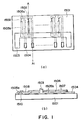
- Figure 1(a) is a plan view of the structure of a conventional recording element substrate of an ink jet recording head employed in an ink jet recording apparatus or the like
- Figure 1(b) is a section of the structure illustrated in Figure 1(a), at A-A1 line.
- a reference numeral 1501 designates a substrate on which recording elements are disposed; 1502, a heat generating element, that is, a layer of heat generating resistor, for example, HfB 2 ; 1503, a common electrode composed of aluminum; 1504, an individual electrode composed of aluminum; 1505a and 1505b, patterned A1 wiring; 1506, a photosensitive polyimide layer as an anti-oxidation layer as well as an insulative layer; and a reference numeral 1508 designates a Ta layer as an anti-cavitation layer.
- the recording element substrate illustrated in Figures 1(a) and 1(b) generates thermal energy from the HfB 2 layer as electric current is flowed through the HfB 2 layer 1510 as a heat generating resistor layer. More specifically, in order to generate thermal energy in the heat generating element 1502, driving current is externally flowed into the HfB 2 layer 1502 through the individual electrode 1504 and the patterned wiring 1505a, and is flowed out through the patterned wiring 1505b and the common electrode 1503.
- FIG. 2 illustrates the structure of a recording element unit employing the recording element substrate described above.
- This recording element unit is provided with ink paths 1520 which lead to corresponding ejection orifices 21.
- a heating element is disposed in each ink path 1520.
- Ink is supplied into a liquid chamber 1530 through an ink supply port (unillustrated) of a top plate 1540, and is delivered to the ink path 1520 from the liquid chamber 1530.
- a plurality of the heat generating elements 1502 which are constituted of a combination of the HfB 2 1510, the dedicated electrode 1504, the patterned wiring 1505a, and the patterned wiring 1505b, are disposed on a single recording substrate.
- Deposing a plurality of heat generating elements on a single recording element substrate makes it possible to realize an ink jet recording apparatus capable of printing a plurality of dots at the same time, increasing recording speed.
- a plurality of lines are recorded at the same time through a single scanning pass, and also, a recording element unit in which a large number of heat generating elements are disposed in high density is very common.
- each recording element In order to record a plurality of dots by disposing a plurality of recording elements in a single recording unit, each recording element must be independently controlled (turned on or off). Such control is possible by providing the recording element unit with a means for selectively driving each of the heat generating elements (hereinafter, driving element).
- driving element a means for selectively driving each of the heat generating elements
- the driving means is formed on a separate substrate (hereinafter, driving element substrate), and is connected to the recording unit.
- driving element substrate a separate substrate
- a structure substantially the same as the structure illustrated in Figures 1(a) and 1(b) is employed. More specifically, a bump-like portion is formed on each of the dedicated electrodes, and, a recording element substrate 5001 attached to the main base board 7005 is joined with the driving element substrate 7002 having a driving IC 7003, by the application of pressure.
- a reference numeral 1704 designates a recording element substrate; 1705, a driving element substrate; 1714 and 1715, electrode portions; and reference numerals 1719 and 1720 designate insulative film. Further, a reference numeral 1703 designates an electrically connective member; 1717, an electrically conductive member; and a reference numeral 1718 designates a supportive member for supporting the electrically conductive member 1717.
- the pitch of the electrically conductive member 1717 is narrower than those of the electrodes 1714 and 1715.
- the recording element substrate 1704, driving element substrate 1705, and electrically connective member 1703 are arranged as shown in Figure 4(a), and then, are pressed together as shown in Figure 4(b).
- Figure 4(c) gives the overall appearance of the joined three members. Since the pitch of the electrically connective member 1717 is smaller than those of the electrodes 1714 and 1715, it is unnecessary to precisely position them; the electrodes 1714 and 1715 can be electrically connected through the electrically connective member 1717, simply by pressing them together.
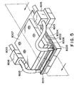
- Figures 5 and 6 illustrate an example of a recording head constituted of a recording element and a separate driving element substrate.
- Figure 5 is a perspective view of the recording head, and Figure 6 is a section thereof, as seen from the direction indicated by an arrow mark in Figure 5.
- a recording element substrate 8001 and a driving element substrate 8002 are fixed to a main base board 8005 and an auxiliary substrate 8004, respectively.
- a filter for removing the bubbles and foreign matter within the recording liquid is fixed to the main base board 8005.
- the connective electrode of the driving element substrate 8002 is accurately positioned relative to the connective electrode of the recording element substrate 8001, and then, the auxiliary base board 8004 is pressed toward the main base board by the pressing plate 8007, with an elastic member 8003 being interposed between the auxiliary base board and the pressing plate 8007.
- Recording liquid is delivered to the recording element unit by an ink delivery system in which the recording element unit is connected to a filtering apparatus 8016 with the use of an ink delivery tube 8013, and the filtering apparatus 8016 and an unillustrated ink container are connected with the use of an ink delivery tube 8013.
- the present invention was made in view of the above described problems which the conventional method has, and its primary object is to greatly simplify the procedure for replacing the recording element substrate, and also to reduce the component count, so that it becomes possible to provide an inexpensive ink jet recording apparatus which allows the recording element substrate to be quickly replaced.
- the structure of the ink recording head in accordance with the present invention made to accomplish the above objects is as follows.
- an ink jet recording apparatus comprises: an ink path leading to an ejection orifice for ejecting ink; a liquid chamber from which ink is delivered to the ink path; a recording element substrate having a plurality of recording elements for generating the ink ejecting energy; a driving element substrate having a plurality of driving elements for selectively driving the recording elements; and a pressing means for providing the pressure for keeping the recording element substrate and the driving element substrate physically in contact with each other, wherein the pressing means comprises an ink delivery system for delivering ink from the liquid chamber to the ink jet head.
- An ink jet head cartridge comprises the ink jet recording head described above, and an ink container which holds the ink to be delivered to the ink jet head.
- An ink jet recording apparatus comprises the ink jet recording apparatus described above, and a means for generating a signal which drives the ink jet recording head.
- component count, and assembly or disassembly steps can be greatly reduced by adopting the structure described above.
- Figure 1 is a schematic view of the recording element substrate in a conventional ink jet recording head.
- Figure 2 is a perspective view of a partially cutaway recording element unit in an ink jet recording head.
- Figure 3 is a schematic drawing depicting how a recording element substrate and a driving element substrate are connected.
- Figure 4 is a schematic drawing depicting the steps through which the recording element substrate and the driving element substrate are electrically connected with the use of an electrically connective member.
- Figure 5 a perspective drawing depicting how the recording element substrate is electrically connected to the driving element substrate using a pressing means.
- Figure 6 is a schematic section of the structure illustrated in Figure 5.
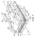
- Figure 7 is a schematic perspective drawing depicting the structure of the ink jet recording head in accordance with the present invention.
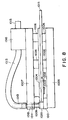
- Figure 8 is a schematic section of the structure illustrated in Figure 7.
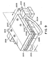
- Figure 9 is a perspective drawing depicting the structure of another ink jet recording apparatus in accordance with the present invention.
- Figure 10 is a schematic section of the structure in Figure 9.
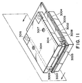
- Figure 11 is a perspective drawing depicting the structure of another ink jet recording head in accordance with the present invention.
- Figure 12 is a schematic section of the structure in Figure 11.
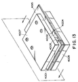
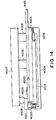
- Figure 13 is a perspective drawing depicting the structure of another ink jet recording apparatus in accordance with the present invention.
- Figure 14 is a schematic section of the structure in Figure 13.
- Figure 15 is a schematic perspective view of an ink jet cartridge.
- Figure 16 is a schematic perspective view of an ink jet recording apparatus employing the head in accordance with the present invention.
- Figures 7 and 8 are drawings which depict the first embodiment of the present invention, Figure 7 being a perspective external view of the ink jet recording head in this embodiment and Figure 8 being a sectional view of the ink jet recording head depicted in Figure 7, as seen from the direction indicated by an arrow mark in Figure 7.
- a reference numeral 1001 designates a recording element substrate; 1020, a liquid path formation member which forms a liquid path or a liquid chamber as it is joined with the recording element substrate as shown in Figure 2; 1002, a driving element substrate; 1003, a driving IC as the driving element; 1004, an auxiliary base board; 1005, a main base board as a member constituting a part of the pressing means; 1006, a spacer; 1007, a pressing plate as a pressing member constituting the pressing means; 1008, an elastic member; 1009, and ink reception port; 1011, an O-ring; 1012, a connective pipe; 1013, an ink delivery tube; 1014, an ink path; 1015, a circuit substrate; 1016, a filtering apparatus; and a reference numeral 1017 designates a screw.
- the recording head in this embodiment is provided with two ink reception ports, each being on the corresponding longitudinal end of the liquid path formation member joined with the recording element substrate 1001 fixed to the main base board 1005.
- the driving element substrate 1002 is fixed to the auxiliary base board along with the circuit substrate 1015, and the driving element substrate 1002 and the circuit substrate 1015 are electrically connected by wire bonding or the like.
- the connective pipe 1012 and the filtering apparatus 1016 which are connected, with the use of the connective tube 1013, to constitute a part of an ink delivery system connected to the ink reception port 1009 of the recording element substrate 1001, are fixed to the pressing plate 1007 which presses together the recording element substrate 1001 and the driving element substrate 1002.
- the connective electrode of the recording element substrate 1001 and-the connective electrode of the driving element substrate 1002- are precisely positioned relative to each other, and are placed between the pressing plate 1007 and the main base board 1005. Then, the pressing plate 1007 and the main base board 1005 are pressed toward each other by the screw 1017, whereby the auxiliary base board 1004 is squeezed toward the main base board 1005 by the elastic member 1008, applying pressure upon the recording element substrate 1001 and the driving element substrate 1002. This pressure places the recording element substrate 1001 and the driving element substrate 1002 firmly in contact with each other, electrically connecting them, and at the same time, connecting the ink delivery systems of both substrates.
- the aforementioned connective portions may be provided with a small bump, or an electrical connector, to improve the state of the connection.
- the ink reception port 1009 of the recording element substrate 1001 is connected to the connective pipe 1012 having been fixed to the pressing plate 1007, with the interposition of the O-ring between the two.
- fixation of the pressing plate 1007 electrically connects the recording element substrate 1001 and the driving element substrate 1002, and also connects the recording element substrate 1001 to the ink delivery system, at the same time.
- assembly efficiency is improved.
- ink delivery systems which are connected to the corresponding ink reception ports 1009 of the liquid path formation member, and both are used as the ink delivery path into the recording element unit.
- one of the system may be used as a system for receiving ink from the recording element unit so that two systems constitute an ink circulation path together with other members.
- Figures 9 and 10 are drawings depicting the second embodiment of the present invention.
- Figure 9 is an external perspective view of the ink jet recording head in this embodiment
- Figure 10 is a schematic section of the same, as seen from the direction indicated by an arrow mark in Figure 9.
- a reference numeral 2001 designates a recording element substrate; 2020, a liquid path formation member; 2002, a driving element substrate; 2003, a driving IC as the driving element; 2004, an auxiliary base board; 2005, a main base board; 2006, a spacer; 2007, a pressing plate; 2008, an elastic member; 2009, an ink reception port; 2011, an O-ring; 2012, a connective pipe; 2013, an ink delivery tube; 2014, an ink path; 2015, a circuit substrate; 2016, a filtering apparatus; and a reference numeral 2017 designates a fixing screw.
- the driving element substrate 2002 and the circuit substrate 2015 are fixed to the main base board 2005, and also are electrically connected to each other by wire bonding or the like.
- the connective pipe 2012 and filtering apparatus 2016, which constitute a part of the ink delivery system connected to the ink reception port 2009 of the liquid path formation member 2020, are connected to each other with the use of the ink delivery tube 2013, but unlike the preceding embodiment, the connective pipe 2012 and the filtering system 2016 are fixed to the main base board 2006.
- the connective electrode of the recording element substrate 2001 and the connective electrode of the driving element substrate 2002 are precisely positioned relative to each other, and pressure is applied from behind the recording element substrate 2001 by the pressing plate 2007, with interposition of the elastic member 2008 between the recording element substrate 2001 and the pressure plate 2007, in the same manner as the first embodiment. As a result, the recording element substrate 2001 and the driving element substrate 2002 are electrically connected.
- the ink reception port 2009 of the recording element substrate 2001 and the connective pipe 2012 fixed to the main base board are connected with the interposition of the O-ring between the two.
- fixation of the pressing plate 2007 makes it possible to electrically connect the recording element substrate 2001 and the driving element substrate 2002, and connect the recording element substrate 2001 to the ink delivery system, at the same time.
- the number of the components attached to the recording element 2001 in this embodiment is smaller. Therefore, the cost . involved when the recording element substrate 2001 is replaced can be minimized.
- Figures 11 and 12 depict the third embodiment of the present invention.
- Figure 11 is an external perspective view of the ink jet recording head in this embodiment
- Figure 12 is a section of the same as seen from the direction indicated by an arrow in Figure 11.
- a reference numeral 3001 designates a recording element substrate; 3020, a liquid path formation member; 3002, a driving element substrate; 3003, a driving IC; 3004, an auxiliary base board; 3005, a main base board; 3006, a spacer; 3007, a pressing plate; 3008, an elastic member; 3009, an ink reception port; 3011, an O-ring; 3012, a connective pipe; 3013, an ink delivery tube; 3014, an ink path; 3015, a circuit substrate; 3016, a filtering apparatus; and a reference numeral 3017 designates a fixing screw.
- the liquid path formation member 3020 is connected to the ink delivery system also by the pressing plate 3007.
- the connective portion to which the ink delivery port 3009 of the recording element substrate 3001 is connected, and the ink delivery path 3014 and filtering apparatus 30016 which constitute a part of the ink delivery system, are integrally formed in the pressing plate 3007.
- the component count can be further reduced compared to Embodiment 1, which makes it possible to reduce the number of assembly steps, the recording head cost, and the recording head size.
- Figures 13 and 14 depict the fourth embodiment of the present invention.
- Figure 13 is an external perspective view of the ink jet recording head in this embodiment
- Figure 14 is a section of the same as seen from the direction indicated by an arrow mark in Figure 13.
- a reference numeral 4001 designates a recording element substrate; 4020, a liquid path formation member; 4002, a driving element substrate; 4003, a driving IC; 4004, an auxiliary base board; 4005, a main base board; 4006, a spacer; 4007, a pressing plate; 4008, an elastic member; 4009, an ink reception port; 4011, an O-ring; 4012, a connective pipe; 4013, an ink delivery tube; 4014, an ink path; 4015, a circuit substrate; 4016, a filtering apparatus; and a reference numeral 4017 designates a fixing screw.
- the same structure as that in Embodiment 2 is employed.
- the liquid path formation member 4020 is connected to the ink delivery system also by the pressing plate 4007.
- the connective portion which is connected to the ink reception port 4009 of the recording element substrate 4001, the ink delivery path 4014, and the filtering apparatus 4016 are integrally formed within the main base board to which the driving element substrate 4001 is fixed. Therefore, the component count can be reduced relative to Embodiment 2, which makes it possible to reduce the number of the assembly steps, the recording head cost, and the recording head size.
- the present invention was described with reference to a heat generating element as the recording element which generates bubbles in ink as it receives a driving signal.
- the application of the present invention is not limited to these embodiments.
- the recording element may be constituted of a piezo-electric element which mechanically displaces itself as it receives a driving signal.
- the present invention was described with reference to an ink jet recording head of a substantial length, but it is needless to say that the present invention is also applicable to a smaller head by reducing the size of each head component.
- a small recording head produced in the aforementioned manner can be used to realize a head cartridge illustrated in Figure 15.
- a reference numeral 1 designates an ink jet recording head
- a reference numeral 2 designates an ink container which holds the ink to be delivered to the ink jet recording head.
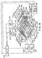
- Figure 16 is a perspective view of an ink jet apparatus comprising an embodiment of an ink jet apparatus which most clearly manifests the characteristic of the present invention.
- the ink jet apparatus in this embodiment comprises full-line heads 201a - 201d in which a plurality of ink ejection orifices are aligned to cover the recording width of the recording medium.
- These full-line heads are fixedly held in parallel to each other by a holder 202, with predetermined intervals, their longitudinal direction being perpendicular to the X direction in the drawing.
- 3,456 ejection orifices are aligned in the Y direction, at a density of 16 orifices per millimeter, which gives this ink jet apparatus a recording width of 218 mm.
- each of these head comprises a plurality of element substrates, and employs a system which uses thermal energy to eject recording liquid.
- the recording liquid ejection from these heads is controlled by a head driver 220.
- These heads inclusive of the holder 202 constitute the head unit of this embodiment, and this head unit is rendered vertically movable by a head moving mean 224.
- each head contains an ink absorbent member formed of sponge or the like.
- the cap is fixed by an unillustrated holder, and the cap and holder constitute a cap unit, which is movable in the X direction by a cap moving means 225.
- Cyan color ink, magenta color ink, yellow color ink, and black ink are delivered from ink containers 204a - 204d to the corresponding color heads through the ink delivery tubes, making it possible to record in color.
- Ink is delivered using capillarity in the ink ejection orifice, and therefore, the positional relationship between the ink container and the head is fixed in such a manner that the liquid surface level in the ink container remains below the ejection orifice by a predetermined distance.
- this apparatus comprises a chargeable seamless belt 206 as a conveying means for conveying a recording paper or fabric 227, that is, the recording medium.
- the belt 206 is routed through a predetermined path by various rollers, being fitted around a driving roller 207, and is drivable by a belt driving motor which is driven by a motor driver 221.
- the belt 206 is driven in the X direction to pass directly below the ejection orifices of the head 201a, 201b, 201c or 201d, and when the belt 206 is in this region, a fixed supporting member 226 prevents the belt 206 from flapping downward.
- head driver 220 head moving means 224, cap moving means 225, motor driver 221, and motor driver 222, are all controlled by a controller circuit 219.
Landscapes
- Particle Formation And Scattering Control In Inkjet Printers (AREA)
- Ink Jet (AREA)
Applications Claiming Priority (3)
| Application Number | Priority Date | Filing Date | Title |
|---|---|---|---|
| JP291133/95 | 1995-11-09 | ||
| JP29113395 | 1995-11-09 | ||
| JP29113395 | 1995-11-09 |
Publications (3)
| Publication Number | Publication Date |
|---|---|
| EP0773107A2 true EP0773107A2 (fr) | 1997-05-14 |
| EP0773107A3 EP0773107A3 (fr) | 1997-10-01 |
| EP0773107B1 EP0773107B1 (fr) | 2002-04-24 |
Family
ID=17764884
Family Applications (1)
| Application Number | Title | Priority Date | Filing Date |
|---|---|---|---|
| EP96308115A Expired - Lifetime EP0773107B1 (fr) | 1995-11-09 | 1996-11-08 | Tête à jet d'encre, cartouche de tête à jet d'encre, et appareil à jet d'encre, comprenant un système d'alimentation en encre |
Country Status (3)
| Country | Link |
|---|---|
| US (1) | US6371604B1 (fr) |
| EP (1) | EP0773107B1 (fr) |
| DE (1) | DE69620846T2 (fr) |
Cited By (1)
| Publication number | Priority date | Publication date | Assignee | Title |
|---|---|---|---|---|
| CN109070612A (zh) * | 2016-05-02 | 2018-12-21 | 马姆杰特科技有限公司 | 用于具有可更换打印头卡匣的模块化打印机的打印模块 |
Families Citing this family (11)
| Publication number | Priority date | Publication date | Assignee | Title |
|---|---|---|---|---|
| WO2006009236A1 (fr) * | 2004-07-22 | 2006-01-26 | Canon Kabushiki Kaisha | Tête d’enregistrement à jet d’encre et appareil d’enregistrement à jet d’encre |
| JP4939184B2 (ja) * | 2005-12-15 | 2012-05-23 | キヤノン株式会社 | 液体吐出ヘッドの製造方法 |
| US9878556B2 (en) * | 2014-01-27 | 2018-01-30 | Hp Indigo B.V. | Valve |
| JP6976735B2 (ja) | 2017-06-15 | 2021-12-08 | キヤノン株式会社 | 液体吐出ヘッドおよび液体吐出装置と液体吐出ヘッドの取付方法 |
| US10682952B2 (en) | 2017-06-28 | 2020-06-16 | Honda Motor Co., Ltd. | Embossed smart functional premium natural leather |
| US11225191B2 (en) | 2017-06-28 | 2022-01-18 | Honda Motor Co., Ltd. | Smart leather with wireless power |
| US11665830B2 (en) | 2017-06-28 | 2023-05-30 | Honda Motor Co., Ltd. | Method of making smart functional leather |
| US10953793B2 (en) | 2017-06-28 | 2021-03-23 | Honda Motor Co., Ltd. | Haptic function leather component and method of making the same |
| US10272836B2 (en) | 2017-06-28 | 2019-04-30 | Honda Motor Co., Ltd. | Smart functional leather for steering wheel and dash board |
| US10742061B2 (en) | 2017-06-28 | 2020-08-11 | Honda Motor Co., Ltd. | Smart functional leather for recharging a portable electronic device |
| US11751337B2 (en) | 2019-04-26 | 2023-09-05 | Honda Motor Co., Ltd. | Wireless power of in-mold electronics and the application within a vehicle |
Citations (1)
| Publication number | Priority date | Publication date | Assignee | Title |
|---|---|---|---|---|
| US5243363A (en) | 1988-07-22 | 1993-09-07 | Canon Kabushiki Kaisha | Ink-jet recording head having bump-shaped electrode and protective layer providing structural support |
Family Cites Families (6)
| Publication number | Priority date | Publication date | Assignee | Title |
|---|---|---|---|---|
| DE3342844A1 (de) * | 1983-11-26 | 1985-06-05 | Philips Patentverwaltung Gmbh, 2000 Hamburg | Mikroplanarer tintenstrahldruckkopf |
| JPH01302829A (ja) | 1988-05-31 | 1989-12-06 | Canon Inc | 電気回路装置 |
| JP2695441B2 (ja) * | 1988-07-11 | 1997-12-24 | キヤノン株式会社 | 記録素子駆動ユニット並びにそれを用いたインクジェット駆動ユニット及びインクジェット記録装置 |
| DE69031872T2 (de) * | 1989-09-18 | 1998-04-30 | Canon Kk | Methode zum Füllen einer Tintenpatrone für Tintenstrahlaufzeichnungsgeräte |
| US5257043A (en) | 1991-12-09 | 1993-10-26 | Xerox Corporation | Thermal ink jet nozzle arrays |
| US6155677A (en) * | 1993-11-26 | 2000-12-05 | Canon Kabushiki Kaisha | Ink jet recording head, an ink jet unit and an ink jet apparatus using said recording head |
-
1996
- 1996-11-08 DE DE69620846T patent/DE69620846T2/de not_active Expired - Fee Related
- 1996-11-08 US US08/747,078 patent/US6371604B1/en not_active Expired - Fee Related
- 1996-11-08 EP EP96308115A patent/EP0773107B1/fr not_active Expired - Lifetime
Patent Citations (1)
| Publication number | Priority date | Publication date | Assignee | Title |
|---|---|---|---|---|
| US5243363A (en) | 1988-07-22 | 1993-09-07 | Canon Kabushiki Kaisha | Ink-jet recording head having bump-shaped electrode and protective layer providing structural support |
Cited By (2)
| Publication number | Priority date | Publication date | Assignee | Title |
|---|---|---|---|---|
| CN109070612A (zh) * | 2016-05-02 | 2018-12-21 | 马姆杰特科技有限公司 | 用于具有可更换打印头卡匣的模块化打印机的打印模块 |
| CN109070612B (zh) * | 2016-05-02 | 2020-05-26 | 马姆杰特科技有限公司 | 用于具有可更换打印头卡匣的模块化打印机的打印模块 |
Also Published As
| Publication number | Publication date |
|---|---|
| EP0773107A3 (fr) | 1997-10-01 |
| US6371604B1 (en) | 2002-04-16 |
| DE69620846D1 (de) | 2002-05-29 |
| DE69620846T2 (de) | 2002-09-26 |
| EP0773107B1 (fr) | 2002-04-24 |
Similar Documents
| Publication | Publication Date | Title |
|---|---|---|
| US5581284A (en) | Method of extending the life of a printbar of a color ink jet printer | |
| US6332677B1 (en) | Stable substrate structure for a wide swath nozzle array in a high resolution inkjet printer | |
| KR0161790B1 (ko) | 잉크 제트 기록 방법 및 잉크 제트 기록 장치 | |
| EP1243419B1 (fr) | Interconnexion électrique pour ensemble de tête d'impression à jet d'encre de grande dimension | |
| EP0773107B1 (fr) | Tête à jet d'encre, cartouche de tête à jet d'encre, et appareil à jet d'encre, comprenant un système d'alimentation en encre | |
| US6281914B1 (en) | Ink jet-type printer device with printer head on circuit board | |
| JPH0825635A (ja) | インクジェットプリント装置およびプリントヘッドユニット | |
| EP1177903B1 (fr) | Tête d'éjection de liquide et appareil d'éjection de liquide | |
| US6095641A (en) | Simplified ink jet recording head and a manufacturing method thereof | |
| JP4427046B2 (ja) | プリント方法 | |
| US6808252B2 (en) | Ink jet recording head and manufacturing method therefor | |
| JP3103177B2 (ja) | インクタンク・ヘッド交換型インクジェット記録装置 | |
| JP3584952B2 (ja) | 積層型インクジェット式記録ヘッド用アクチュエータユニット、及びこれを使用したインクジェット式記録ヘッド | |
| JP4715350B2 (ja) | 液体吐出ヘッド及び液体吐出装置 | |
| EP0783969B1 (fr) | Tête d'enregistrement, appareil d'enregistrement et méthode de fabrication de la tête d'enregistrement | |
| JP3554120B2 (ja) | インク供給機構を持つインクジェットヘッド、インクジェットヘッドカートリッジおよびインクジェット装置 | |
| US5701147A (en) | Ink jet head and ink jet apparatus using same | |
| US6007185A (en) | Recording head, head cartridge and recording apparatus with flexible substrate coupling | |
| JPH106518A (ja) | インクジェット記録装置 | |
| JP3646835B2 (ja) | プリンタのインク噴射装置 | |
| JPH07290711A (ja) | インクジェットヘッド、インクジェットヘッドカートリッジ、インクジェットヘッドキット、インクジェット記録装置、インクジェットヘッドの製造方法およびインクの注入方法 | |
| JPH10217455A (ja) | プリンタのインク噴射装置 | |
| JP4441244B2 (ja) | インクジェット記録ヘッドおよびインクジェット記録装置 | |
| JP3260546B2 (ja) | インクジェットヘッド用基体、インクジェットヘッド、該インクジェットヘッド用基体の製造方法、および該インクジェットヘッドの製造方法 | |
| JPH11254704A (ja) | 液体吐出ヘッドおよびヘッドカートリッジならびに画像形成装置 |
Legal Events
| Date | Code | Title | Description |
|---|---|---|---|
| PUAI | Public reference made under article 153(3) epc to a published international application that has entered the european phase |
Free format text: ORIGINAL CODE: 0009012 |
|
| AK | Designated contracting states |
Kind code of ref document: A2 Designated state(s): DE FR GB IT |
|
| PUAL | Search report despatched |
Free format text: ORIGINAL CODE: 0009013 |
|
| AK | Designated contracting states |
Kind code of ref document: A3 Designated state(s): DE FR GB IT |
|
| 17P | Request for examination filed |
Effective date: 19980211 |
|
| 17Q | First examination report despatched |
Effective date: 19991012 |
|
| GRAG | Despatch of communication of intention to grant |
Free format text: ORIGINAL CODE: EPIDOS AGRA |
|
| GRAG | Despatch of communication of intention to grant |
Free format text: ORIGINAL CODE: EPIDOS AGRA |
|
| GRAG | Despatch of communication of intention to grant |
Free format text: ORIGINAL CODE: EPIDOS AGRA |
|
| GRAH | Despatch of communication of intention to grant a patent |
Free format text: ORIGINAL CODE: EPIDOS IGRA |
|
| REG | Reference to a national code |
Ref country code: GB Ref legal event code: IF02 |
|
| GRAH | Despatch of communication of intention to grant a patent |
Free format text: ORIGINAL CODE: EPIDOS IGRA |
|
| GRAA | (expected) grant |
Free format text: ORIGINAL CODE: 0009210 |
|
| AK | Designated contracting states |
Kind code of ref document: B1 Designated state(s): DE FR GB IT |
|
| REG | Reference to a national code |
Ref country code: GB Ref legal event code: FG4D |
|
| REF | Corresponds to: |
Ref document number: 69620846 Country of ref document: DE Date of ref document: 20020529 |
|
| ET | Fr: translation filed | ||
| PLBE | No opposition filed within time limit |
Free format text: ORIGINAL CODE: 0009261 |
|
| STAA | Information on the status of an ep patent application or granted ep patent |
Free format text: STATUS: NO OPPOSITION FILED WITHIN TIME LIMIT |
|
| 26N | No opposition filed |
Effective date: 20030127 |
|
| PGFP | Annual fee paid to national office [announced via postgrant information from national office to epo] |
Ref country code: FR Payment date: 20061124 Year of fee payment: 11 |
|
| PGFP | Annual fee paid to national office [announced via postgrant information from national office to epo] |
Ref country code: IT Payment date: 20061130 Year of fee payment: 11 |
|
| REG | Reference to a national code |
Ref country code: FR Ref legal event code: ST Effective date: 20080930 |
|
| PG25 | Lapsed in a contracting state [announced via postgrant information from national office to epo] |
Ref country code: FR Free format text: LAPSE BECAUSE OF NON-PAYMENT OF DUE FEES Effective date: 20071130 |
|
| PGFP | Annual fee paid to national office [announced via postgrant information from national office to epo] |
Ref country code: DE Payment date: 20081130 Year of fee payment: 13 |
|
| PGFP | Annual fee paid to national office [announced via postgrant information from national office to epo] |
Ref country code: GB Payment date: 20081124 Year of fee payment: 13 |
|
| PG25 | Lapsed in a contracting state [announced via postgrant information from national office to epo] |
Ref country code: IT Free format text: LAPSE BECAUSE OF NON-PAYMENT OF DUE FEES Effective date: 20071108 |
|
| GBPC | Gb: european patent ceased through non-payment of renewal fee |
Effective date: 20091108 |
|
| PG25 | Lapsed in a contracting state [announced via postgrant information from national office to epo] |
Ref country code: DE Free format text: LAPSE BECAUSE OF NON-PAYMENT OF DUE FEES Effective date: 20100601 |
|
| PG25 | Lapsed in a contracting state [announced via postgrant information from national office to epo] |
Ref country code: GB Free format text: LAPSE BECAUSE OF NON-PAYMENT OF DUE FEES Effective date: 20091108 |