EP0772991A1 - Sensor controlled cooking unit - Google Patents
Sensor controlled cooking unit Download PDFInfo
- Publication number
- EP0772991A1 EP0772991A1 EP96117198A EP96117198A EP0772991A1 EP 0772991 A1 EP0772991 A1 EP 0772991A1 EP 96117198 A EP96117198 A EP 96117198A EP 96117198 A EP96117198 A EP 96117198A EP 0772991 A1 EP0772991 A1 EP 0772991A1
- Authority
- EP
- European Patent Office
- Prior art keywords
- pot
- sensor
- cooking unit
- unit according
- controlled cooking
- Prior art date
- Legal status (The legal status is an assumption and is not a legal conclusion. Google has not performed a legal analysis and makes no representation as to the accuracy of the status listed.)
- Ceased
Links
Images

Classifications
-
- A—HUMAN NECESSITIES
- A47—FURNITURE; DOMESTIC ARTICLES OR APPLIANCES; COFFEE MILLS; SPICE MILLS; SUCTION CLEANERS IN GENERAL
- A47J—KITCHEN EQUIPMENT; COFFEE MILLS; SPICE MILLS; APPARATUS FOR MAKING BEVERAGES
- A47J27/00—Cooking-vessels
- A47J27/002—Construction of cooking-vessels; Methods or processes of manufacturing specially adapted for cooking-vessels
-
- A—HUMAN NECESSITIES
- A47—FURNITURE; DOMESTIC ARTICLES OR APPLIANCES; COFFEE MILLS; SPICE MILLS; SUCTION CLEANERS IN GENERAL
- A47J—KITCHEN EQUIPMENT; COFFEE MILLS; SPICE MILLS; APPARATUS FOR MAKING BEVERAGES
- A47J36/00—Parts, details or accessories of cooking-vessels
- A47J36/32—Time-controlled igniting mechanisms or alarm devices
-
- F—MECHANICAL ENGINEERING; LIGHTING; HEATING; WEAPONS; BLASTING
- F24—HEATING; RANGES; VENTILATING
- F24C—DOMESTIC STOVES OR RANGES ; DETAILS OF DOMESTIC STOVES OR RANGES, OF GENERAL APPLICATION
- F24C7/00—Stoves or ranges heated by electric energy
- F24C7/08—Arrangement or mounting of control or safety devices
- F24C7/082—Arrangement or mounting of control or safety devices on ranges, e.g. control panels, illumination
- F24C7/083—Arrangement or mounting of control or safety devices on ranges, e.g. control panels, illumination on tops, hot plates
Definitions
- the invention relates to a sensor-controlled cooking unit, consisting of a cooking device, sensors and hob, wherein an infrared sensor assigned to the sensor-controlled cooking unit is arranged slightly above the hob in relation to the cooking zone and is integrated in a constructive functional unit.
- the object of the present invention is to understand a sensor-controlled cooking unit as a sensor-controlled system of the hob and cooking appliance, to define a system pot which is adapted to the hotplate sensor system and the bowl electronics, the system pot advantageously communicates with the sensor-controlled cooking unit.
- the arrangement according to the invention for solving this problem is characterized in that in the sensor-controlled cooking unit the hob, cooking device and sensor system are systematically connected to one another, adapted to one another and optimized, that the cooking device is a system pot with a standardized emission factor, based on a wavelength range of the infrared radiation of 8 ⁇ m ⁇ ⁇ ⁇ 14 ⁇ m that the system pot adheres to optimized pot wall and pot bottom thickness ranges and that the system pot has an adapted contact point between the pot lid and the pot rim.
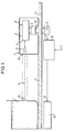
- a sensor-controlled glass ceramic hotplate unit which consists of a pot 1, an additional device 4, a glass ceramic cooking surface 11, a bowl electronics 13 and a radiant heating source 16.
- the pot 1 placed with the food on the glass ceramic cooking surface 11 corresponds to the additional device via an infrared sensor.
- infrared sensor instead of the additional device, permanently installed or retractable infrared sensor units arranged in a structural unit can also be arranged.
- the infrared sensor generates an infrared measuring spot 2a on the pot 1, which originates from the infrared sensor 5 located in the additional device 4.
- the infrared sensor 5 works via an exit window for infrared rays 2b, which is arranged at an exit point of the additional devices 4.
- Electronics 6 required for the additional device 4 are in correspondence with display elements 7 and control elements 8 of the additional device and an infrared sensor and receiver unit 9 in the additional device.
- the infrared transmitter and receiver unit 9 of the additional device has a window for infrared radiation, which corresponds directly via a same unit 12 in the trough separated by the glass ceramic cooking surface 11.
- the infrared sensor and receiver system 12 of the hob operates bidirectionally with the hob electronics 13, which is fed by a mains voltage supply module 14. Via a bundle of lines 15, the radiant heating of the hotplate 16 is subjected to hotplate power connections by the hob electronics 13.
- a sensor-controlled cooking unit is largely based on a functional pot, which can be referred to as a system pot if it is provided with a sensor-controlled bowl unit in a fixed assignment for the sensor cooking mode.
- cooking on a sensor-controlled glass ceramic hotplate unit is to be understood as a system of pot and glass ceramic cooking surface. Outside the system pot assignment, it should also be possible to use other pots suitable for infrared technology, the invention providing indications of how existing pots could be converted into second order system pots.
- a system pot is shown in FIG. 5.
Abstract
Description
Die Erfindung bezieht sich auf eine sensorgesteuerte Garungseinheit, bestehend aus Gargerät, Sensorik und Kochfeld, wobei ein der sensorgesteuerten Garungseinheit zugeordneter Infrarotsensor kochstellenbezogen leicht erhöht oberhalb des Kochfeldes angeordnet und in einer konstruktiven Funktionseinheit integriert ist.The invention relates to a sensor-controlled cooking unit, consisting of a cooking device, sensors and hob, wherein an infrared sensor assigned to the sensor-controlled cooking unit is arranged slightly above the hob in relation to the cooking zone and is integrated in a constructive functional unit.
Eine Anordnung zum Messen der Temperatur in einem Kochtopf ist durch die Patentschrift DE 33 41 234 C1 bekannt geworden. Diese Erfindung betrifft eine Anordnung zum Messen der Temperatur eines auf einer Heizplatte erwärmten Kochtopfes mit Kochgut, wobei mit Hilfe eines Strahlungsfühlers die Temperatur des Kochgutes ermittelbar ist.An arrangement for measuring the temperature in a saucepan has become known from the
Die Aufgabe der vorlegenden Erfindung besteht darin, eine sensorgesteuerte Garungseinheit als sensorgesteuertes System von Kochfeld und Gargerät aufzufassen, einem auf die Kochstellensensorik und Muldenelektronik angepaßten Systemtopf zu definieren, wobei der Systemtopf in vorteilhafter Weise mit der sensorgesteuerten Garungseinheit kommuniziert.The object of the present invention is to understand a sensor-controlled cooking unit as a sensor-controlled system of the hob and cooking appliance, to define a system pot which is adapted to the hotplate sensor system and the bowl electronics, the system pot advantageously communicates with the sensor-controlled cooking unit.
Die erfindungsgemäße Anordnung zur Lösung dieser Aufgabe ist dadurch gekennzeichnet, daß in der sensorgesteuerten Garungseinheit Kochfeld, Gargerät und Sensorik systemhaft miteinander verbunden, aufeinander angepaßt und optimiert sind, daß das Gargerät ein Systemtopf mit einem normierten Emissionsfaktor ist, bezogen auf einen Wellenlängenbereich der Infrarotstrahlung von 8 µm ≦ λ ≦ 14 µm, daß der Systemtopf optimierte Topfwand- und Topfboden-Dickenbereiche einhält und daß der Systemtopf eine angepaßte Kontaktstelle zwischen Topfdeckel und Topfrand besitzt.The arrangement according to the invention for solving this problem is characterized in that in the sensor-controlled cooking unit the hob, cooking device and sensor system are systematically connected to one another, adapted to one another and optimized, that the cooking device is a system pot with a standardized emission factor, based on a wavelength range of the infrared radiation of 8 µm ≦ λ ≦ 14 µm that the system pot adheres to optimized pot wall and pot bottom thickness ranges and that the system pot has an adapted contact point between the pot lid and the pot rim.
Vorteilhafte Ausgestaltungen der Erfindung sind in den Unteransprüchen enthalten. Ein Ausführungsbeispiel nach der Erfindung ist im folgenden anhand der Zeichnung näher beschrieben. Es zeigt:
- Fig. 1
- ein sensorgesteuertes Garungssystem,
- Fig. 2
- ein erstes Detail des Systemtopfes,
- Fig. 3
- eine zweites Detail des Systemtopfes,
- Fig. 4
- ein drittes Detail des Systemtopfes,
- Fig. 5
- die Gesamtheit des Systemtopfes.
- Fig. 1
- a sensor-controlled cooking system,
- Fig. 2
- a first detail of the system pot,
- Fig. 3
- a second detail of the system pot,
- Fig. 4
- a third detail of the system pot,
- Fig. 5
- the entirety of the system pot.
Gemäß der Figur 1 ist eine sensorgesteuerte Glaskeramik-Kochstelleneinheit dargestellt, die aus einem Topf 1, einem Zusatzgerät 4, einer Glaskeramik-Kochflächee 11, einer Muldenelektronik 13 und einer Strahlungsheizquelle 16 besteht.According to FIG. 1, a sensor-controlled glass ceramic hotplate unit is shown, which consists of a pot 1, an additional device 4, a glass
Der mit dem Kochgut auf der Glaskeramik-Kochfläche 11 plazierte Topf 1 korrespondiert mit dem Zusatzgerät über einen Infrarotsensor. Anstelle des Zusatzgerätes können auch fest installierte oder in einer konstruktiven Einheit angeordnete, versenkbare Infrarotsensoreinheiten angeordnet sein. Der Infrarotsensor erzeugt am Topf 1 einen Infrarotmeßfleck 2a, der vom im Zusatzgerät 4 befindlichen Infrarotsensor 5 herrührt. Der Infrarotsensor 5 funktioniert über ein Aus trittsfenster für Infrarotstrahlen 2b, das an einer Austrittsstelle des Zusatzgeräte 4 angeordnet ist. Eine für das Zusatzgerät 4 notwendige Elektronik 6 befindet sich in Korrespondenz mit Anzeigeelementen 7 und Bedienelementen 8 des Zusatzgerätes und einer Infrarotsensor- und Empfängereinheit 9 im Zusatzgerät. Die Infrarotsender und -empfängereinheit 9 des Zusatzgerätes besitzt ein Fenster für Infrarotstrahlung, das über einer gleichen Einheit 12 in der Mulde durch die Glaskeramik-Kochfläche 11 getrennt direkt korrespondiert. Die Infrarotsensor- und Empfangsanlage 12 der Mulde verkehrt bidirektional mit der Kochmuldenelektronik 13, die von einem Netzspannungs-Zuführungsmodul 14 gespeist wird. Über ein Leitungsbündel 15 wird die Strahlungsheizung der Kochstelle 16 mit Kochstellen-Leistungszuschaltungen durch die Kochmuldenelektronik 13 beaufschlagt.The pot 1 placed with the food on the glass
Als Alternative zu dieser konstruktiven Lösung gemäß Figur 1 ist es möglich, den Infrarotsensor in einer konstruktiven Funktonseinheit zu integrieren, die mit dem Kochmuldenrahmen verbunden ist, wobei die Funktionseinheit auf einen Mikroschalter einwirkt, der der Elektronikeinheit die Einsatzbereitschaft des Sensorsystems signalisiert.As an alternative to this constructive solution according to FIG. 1, it is possible to integrate the infrared sensor in a constructive functional unit which is connected to the hob frame, the functional unit acting on a microswitch which signals the readiness for use of the sensor system to the electronic unit.
Die Vorteile einer sensorgesteuerten Garungseinheit sind in hohem Maße auf einen funktionsfähigen Topf abgestellt, der als Systemtopf bezeichnet werden kann, wenn er mit einer sensorgesteuerten Muldeneinheit in fester Zuordnung für den Sensorkochbetrieb vorgesehen ist. Diesbezüglich ist das Kochen auf einer sensorgesteuerten Glaskeramik-Kochstelleneinheit als System von Topf und Glaskeramik-Kochfläche aufzufassen. Außerhalb der Systemtopfzuordnung soll es dabei auch möglich sein, andere für Infrarottechnik taugliche Töpfe einzusetzen, wobei die Erfindung Hinweise darauf gibt, wie vorhandene Töpfe zu Systemtöpfen zweiter Ordnung gewandelt werden könnte. Ein solcher Systemtopf ist gemäß Figur 5 dargestellt.The advantages of a sensor-controlled cooking unit are largely based on a functional pot, which can be referred to as a system pot if it is provided with a sensor-controlled bowl unit in a fixed assignment for the sensor cooking mode. In this regard, cooking on a sensor-controlled glass ceramic hotplate unit is to be understood as a system of pot and glass ceramic cooking surface. Outside the system pot assignment, it should also be possible to use other pots suitable for infrared technology, the invention providing indications of how existing pots could be converted into second order system pots. Such a system pot is shown in FIG. 5.
Erkennbar ist ein Systemtopf 51, ein Systemtopfdeckel 52, eine Kontaktstelle 53, eine Systemtopfwand 54, eine Füllstandsmarkierung 55, eine Emailschicht 56 und ein Topfboden 57 dargestellt. Der dargestellte Systemtopf 51 hat vielerlei sehr verschiedene Eigenschaften, die teilweise nur kompromißhaft in einem Topf gemeinsam realisiert werden können.
- Emissionsfaktor der Topfwand.
In dem Bereich der Topfwand, der vom Infrarotsensor zur Temperaturmessung betrachtet werden kann, sollte die Topfwand einen hohen Infrarot-Emissionsfaktor von nahezu 1 haben. Praktisch wird der erreichbare Wert bei ca. 0,99 liegen. Dieser Emissionsfaktor muß nur in einem Wellenlängenbereich von 8 um ≦ λ ≦14 µm konstant sein. Dies wird dadurch erreicht, daß die Topfwand durch eine Oberfläche aus Email oder geeignete Kunststoffe gebildet wird. Ein Topf, der für das System nicht tauglich erscheint, kann durch eine Beschichtung, beispielsweise mit Folie, Lack oder anderen nachträglich aufgebrachten Mitteln, infrarottauglich ertüchtigt werden. Die Festlegung auf den genannten Bereich des Emissionsfaktors hat den weiteren Vorteil, daß angetrocknete Reste von zufällig an die Topfwand geratenen Lebensmitteln den gleichen Emissionsfaktor haben, wie die beschichtete Topfwand. Eine Verschmutzung der Topfwand kann daher das Ergebnis der Temperaturmessung nicht verfälschen. - Abstrahlcharakteristik der Topfoberfläche.
Die Abstrahlcharakteristik der Topfwand muß der eines Lam bert-Strahlers (Kosinus-Strahlers) entsprechen. Das bedeutet, daß der Infrarotsensor auch unter einem von 90° abweichenden Winkel auf die betrachtete Topfwand gerichtet sein darf, ohne daß die Funktionsfähigkeit des Systems in Frage gestellt wäre. Konstruktiv bedeutet das, der Infrarotsensor muß nicht genau radial auf denSystemtopf 51 ausgerichtet sein. Damit die Topfoberfläche die Abstrahlcharakteristik eines Lambert-Strahlers hat, muß die Emailoberfläche zumindest im betrachteten Infrarotbereich eine gewisse Welligkeit besitzen. Daher ist es nicht möglich, eine in sich dichte glatte Oberfläche zu erzeugen. Da rauhes Email im Haushaltbereich schwerlich einsetzbar ist (schwer zu reinigen und daher hygienisch bedenklich), sollte die Emailschicht eine glatte Oberfläche besitzen. Um sie für die Betrachtung des Infrarotsensors als rauh erscheinen zu lassen, wird eine Ausbildung der Emailschicht als Schichtfolge vorgeschlagen. Dabei ist die letzte, dem Benutzer zugewandte Emailschicht relativ glatt und im infraroten Bereich transparent. Die darauf folgende Schicht kann dann beliebig wellig sein. Eine solche transparente Schicht kann dabei auch aus einem einschichtigen Email bestehen, das aufgrund hoher Brenntemperaturen an der Oberfläche transparent verglast ist. - Dicke der Topfwand.
Die Topfwand sollte so dünn sein, daß Änderungen in der Lebensmitteltemperatur außen schnellstens bemerkt werden. Andererseits muß aber auch die Topfwand dick genug sein, daß ihre Wärmekapazität ausreicht, um Schwankungen der Lebensmitteltemperatur, die aufgrund der Konvektion im Lebensmittel selbst (besonders in Wasser) zuverlässig ausgemittelt werden. Versuche dazu haben ergeben, daß das am besten mit einer Wanddicke von ca. 1 mm bis 2,4 mm erreichbar ist. - Erkennung der Füllhöhe.
Der vom Infrarotsensor betrachtete Meßfleck auf der Topfwand muß auf der Innenseite mit Lebensmittel bedeckt sein, damit die außen gemessene Temperatur der des Lebensmittels entspricht. Die aktuelle Füllhöhe ist für den durchschnittlichen Benutzer nur sehr schwer einschätzbar. An der Topfinnenwand angebrachte Markierungen können dabei nur bedingt hilfreich sein, da sie nur bei geöffneten Topf sichtbar wären. Daher wird vorgeschlagen, die Beschichtung der Topfaußenwand mit einem Material auszuführen, das seine Farbe abhängig von der Temperatur ändert. Diese gegebenenfalls etwas aufwendigere Prozedur stellt jedoch sicher, daß die Füllhöhe jederzeit von außen problemlos erkannt wird. - Höhe des Meßfleckes über der Glaskeramik.
DerMeßfleck muß mindestens 35 mm über der Glaskeramik und nicht im Bereich des Überganges vom Topfboden zur Topfwand angebracht sein. Dies liegt darin begründet, daß ein Topf bei einer Erwärmung beispielsweise auf Induktionsmulden in Topfbodenbereich stark erwärmt werden kann. Da durch einen zu hohen Meßfleck die Mindestfüllmenge des Topfes ansteigt, ergibt sich der obengenannte Kompromiß. Ein Meßfleck kann dabei mit einem minimalen Durchmesser von ca. 10bis 15 mm realisiert werden. Für eine optimierte Lage der Infrarot-Abstrahlfläche ergibt sich damit auf der Topfwand ein Bereich von ca. 35 bis 50 mm über der Kochfläche. - Dicke des Topfbodens.
Der Topfboden eines Systemtopfes 1 muß hinreichend dick sein bzw. eine ausreichende Wärmekapazität haben, um beim Einschalten der Heizung der Kochstelle ein punktuelles Überschwingen der Temperatur zu vermeiden, so daß das Lebensmittel nicht anbrennen oder anhängen kann. Dies wird, wie Versuche bestätigt haben, am besten mit einer Bodendicke ab 2 mm Stärke erreicht. - Optimale Gestaltung von oberem Topfrand und Topfdeckelrand.
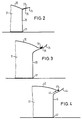
Gemäß der Figuren 2, 3 und 4 sind Details des Systemtopfes 51 dargestellt, die eine optimierte Gestaltung des oberen Topfrandes unter Einbezug des Topfdeckelrandes vermitteln.
Es sind erkennbar dieTopfdetailstücke und 41, dieTopfdeckel Topfdeckelränder Topfränder 24, 34 und 44, die Kontaktstellen zwischen Deckelrand und Topfrand 25, 35und 45, dieTopfwände und 46 sowie dieTopfböden der Kontaktstelle 35, deutlich verbessert. Ein ähnliches Verhalten Kann, wie in Figur 4 dargstellt ist, ein runder Deckelabschluß leisten. Dabei ist die Gleitfähigkeit des Topfdeckelrandes 43 gegenüber einem in derKontaktstelle 45 entstehenden Wasserfilmes optimal.
- Emission factor of the pot wall.
In the area of the pot wall, which can be viewed by the infrared sensor for temperature measurement, the pot wall should have a high infrared emission factor of almost 1. In practice, the achievable value will be around 0.99. This emission factor only has to be constant in a wavelength range of 8 µm ≦ λ ≦ 14 µm. This is achieved in that the pot wall is formed by a surface made of enamel or suitable plastics. A pot that does not appear to be suitable for the system can go through a coating, for example with foil, lacquer or other subsequently applied agents, is upgraded to be suitable for infrared radiation. The definition of the range of the emission factor mentioned has the further advantage that dried-on residues of food accidentally touching the wall of the pot have the same emission factor as the coated wall of the pot. Contamination of the wall of the pot cannot falsify the result of the temperature measurement. - Radiation characteristics of the pot surface.
The radiation pattern of the pot wall must correspond to that of a Lambert emitter (cosine emitter). This means that the infrared sensor may also be directed at the pot wall under consideration at an angle other than 90 ° without the functionality of the system being called into question. In terms of construction, this means that the infrared sensor does not have to be exactly radially aligned with thesystem pot 51. So that the pot surface has the radiation characteristic of a Lambert radiator, the enamel surface must have a certain ripple, at least in the infrared range under consideration. It is therefore not possible to create a tight, smooth surface. Since rough enamel is difficult to use in the household (difficult to clean and therefore hygienically questionable), the enamel layer should have a smooth surface. In order to make them appear to be rough for viewing the infrared sensor, it is proposed to design the enamel layer as a layer sequence. The last enamel layer facing the user is relatively smooth and transparent in the infrared range. The following The layer can then be any wavy. Such a transparent layer can also consist of a single-layer enamel, which is glazed transparently on the surface due to high firing temperatures. - Thickness of the pot wall.
The wall of the pot should be so thin that changes in the food temperature can be noticed quickly on the outside. On the other hand, the wall of the pot must also be thick enough that its heat capacity is sufficient to withstand fluctuations in the food temperature, which are reliably averaged out due to convection in the food itself (especially in water). Experiments have shown that this can best be achieved with a wall thickness of approximately 1 mm to 2.4 mm. - Detection of the fill level.
The measuring spot on the pot wall observed by the infrared sensor must be covered on the inside with food so that the temperature measured on the outside corresponds to that of the food. The current fill level is very difficult to estimate for the average user. Markings on the inner wall of the pot can only be of limited help, as they would only be visible when the pot was open. It is therefore proposed to coat the outer wall of the pot with a material that changes color depending on the temperature. However, this procedure, which may be somewhat more complex, ensures that the fill level is easily recognized from the outside at all times. - Height of the measuring spot above the glass ceramic.
The measuring spot must be at least 35 mm above the glass ceramic and not in the area of the transition from the bottom of the pot to the wall of the pot. This is due to the fact that a pot can be strongly heated when heated, for example on induction troughs in the pot bottom area. Since the minimum filling quantity of the pot increases due to an excessively high measuring spot, the above-mentioned compromise results. A measuring spot can be realized with a minimum diameter of approx. 10 to 15 mm. For an optimized position of the infrared radiation area, this results in an area of approx. 35 to 50 mm above the cooking surface on the pot wall. - Thickness of the bottom of the pot.
The pot bottom of a system pot 1 must be sufficiently thick or have sufficient heat capacity in order to prevent the temperature from overshooting at certain times when the heating of the hotplate is switched on, so that the food cannot burn or append. As tests have confirmed, this is best achieved with a soil thickness of 2 mm or more. - Optimal design of the top edge of the pot and the rim of the pot lid.
According to FIGS. 2, 3 and 4, details of thesystem pot 51 are shown, which convey an optimized design of the top pot rim, including the pot lid rim.
Thepot detail pieces pot lids pot edge pot walls 26 can be seen , 36 and 46 as well as the pot bases 27, 37 and 47. From FIGS. 2 to 4 it can essentially be seen that the contact point between the pot lid and the rim of the pot should be shaped as far as possible so that after a possible steam pressure-related lifting of the lid, the lid automatically again slides into the original starting position, and thus a well-closing pot can be assumed during the entire cooking process. This is absolutely necessary, since in the case of a pot that is not completely filled to the minimum mark, the condensing water, which appears as a water film on the respective pot wall, maintains the system sensor = pot functional. The condensed water film simulates non-existing fill levels and allows temperature-appropriate cooking. The safe function and position of the pot lid necessary for this is advantageously achieved in that the pot edge according to FIG. 2 has, for example, a light funnel shape. The pot lid always slides back into the intended position on a water film created by condensation. This does not require a circular pot, as is often assumed. It is advantageous that the resulting water film compensates for minor inaccuracies in the fit of the pot lid, as can arise from manufacturing errors or improper handling of the cookware. The top edge of the lid increases to its normal position due to the pot rim design rising towards the outside. At least, however, the lid should lie flat on the in a small circumferential area of the lid edge Rest the pot rim, as can be seen in FIG. 3. As a result, the guidance of the pot lid at the pot edge, that is to say in thecontact point 35, is significantly improved. A similar behavior can, as shown in Figure 4, achieve a round cover. The sliding ability of the rim of the pot lid 43 is optimal with respect to a water film formed in thecontact point 45.
Die dargestellten Vorzüge eines Systemtopfes sind für eine sensorgesteuerte Garungseinheit insofern notwendig, als daß durch das Sensorkochen nur mit Hilfe dieser Maßnahme genügend sicher Temperaturkonstanz und sensorgesteuertes Garen ermöglicht wird, wobei sowohl nahrungsmittelgerechtes Garen als auch energiesparendes Garen erfolgreich praktiziert werden kann.The advantages shown of a system pot are necessary for a sensor-controlled cooking unit insofar as that with the help of the sensor cooking temperature constancy and sensor-controlled cooking is only possible with sufficient certainty, both food-compatible cooking and energy-saving cooking being successfully practiced.
Claims (13)
daß in der sensorgesteuerten Garungseinheit Kochfeld, Gargerät und Sensorik systemhaft miteinander verbunden, aufeinander angepaßt und optimiert sind, daß das Gargerät ein Systemtopf (51) mit einem normierten Emissionsfaktor ist, bezogen auf einen Wellenlängenbereich der Infrarotstrahlung von 8 µm ≦ λ ≦ 14 µm daß der Systemtopf (51) optimierte Topfwand- und Topfboden-Dickenbereiche einhält, und daß der Systemtopf (51) eine angepaßte Kontaktstelle (53) zwischen Topfdeckel (52) und Topfrand (54) besitzt.Sensor-controlled cooking unit, consisting of cooking device, sensors and hob, wherein an infrared sensor assigned to the sensor-controlled cooking unit is arranged slightly above the hob in relation to the cooking point and is integrated in a constructive functional unit, characterized in that
that in the sensor-controlled cooking unit hob, cooking device and sensors are systematically connected to one another, adapted to one another and optimized, that the cooking device is a system pot (51) with a standardized emission factor, based on a wavelength range of the infrared radiation of 8 µm ≦ λ ≦ 14 µm that the System pot (51) maintains optimized pot wall and pot bottom thickness ranges, and that the system pot (51) has an adapted contact point (53) between pot lid (52) and pot rim (54).
Applications Claiming Priority (2)
| Application Number | Priority Date | Filing Date | Title |
|---|---|---|---|
| DE19541632 | 1995-11-08 | ||
| DE19541632A DE19541632A1 (en) | 1995-11-08 | 1995-11-08 | Sensor-controlled cooking unit |
Publications (1)
| Publication Number | Publication Date |
|---|---|
| EP0772991A1 true EP0772991A1 (en) | 1997-05-14 |
Family
ID=7776931
Family Applications (1)
| Application Number | Title | Priority Date | Filing Date |
|---|---|---|---|
| EP96117198A Ceased EP0772991A1 (en) | 1995-11-08 | 1996-10-25 | Sensor controlled cooking unit |
Country Status (2)
| Country | Link |
|---|---|
| EP (1) | EP0772991A1 (en) |
| DE (1) | DE19541632A1 (en) |
Cited By (3)
| Publication number | Priority date | Publication date | Assignee | Title |
|---|---|---|---|---|
| EP0931496A1 (en) * | 1998-01-23 | 1999-07-28 | Seb S.A. | Kitchen utensil comprising a temperature sensor for measuring its temperature |
| WO2000034839A1 (en) * | 1998-12-08 | 2000-06-15 | Koninklijke Philips Electronics N.V. | Electrical thermal appliance with remotely mounted temperature sensor |
| WO2021185580A1 (en) * | 2020-03-19 | 2021-09-23 | BSH Hausgeräte GmbH | Domestic pef cooking device |
Families Citing this family (5)
| Publication number | Priority date | Publication date | Assignee | Title |
|---|---|---|---|---|
| DE19856140A1 (en) * | 1998-12-04 | 2000-06-08 | Bsh Bosch Siemens Hausgeraete | Sensor-controlled cooktop with a sensor unit located below the cooktop |
| DE19948472C2 (en) * | 1999-10-08 | 2002-11-28 | Fissler Gmbh | cooking vessel |
| DE102004059160A1 (en) | 2004-12-08 | 2006-06-14 | BSH Bosch und Siemens Hausgeräte GmbH | hob |
| DE102006023190A1 (en) * | 2006-05-17 | 2007-11-22 | BSH Bosch und Siemens Hausgeräte GmbH | Temperature sensing device |
| DE102010042138A1 (en) | 2010-10-07 | 2012-04-12 | BSH Bosch und Siemens Hausgeräte GmbH | Temperature Measurement System |
Citations (5)
| Publication number | Priority date | Publication date | Assignee | Title |
|---|---|---|---|---|
| DE3341234C1 (en) | 1983-11-15 | 1985-05-15 | Kurt Wolf & Co Kg, 7547 Wildbad | Arrangement for measuring the temperature in a heating system consisting of a hot plate and a saucepan |
| DE3410465A1 (en) * | 1984-03-22 | 1985-10-03 | Licentia Patent-Verwaltungs-Gmbh, 6000 Frankfurt | Method and device for determining the boiling of liquids and/or foods |
| DE3538353C1 (en) * | 1985-10-29 | 1986-09-04 | Kurt Wolf & Co Kg, 7547 Wildbad | Arrangement for measuring the temperature in a heating system consisting of a hot plate and a saucepan |
| DE3811925C1 (en) * | 1988-04-09 | 1989-03-02 | Kurt Wolf & Co Kg, 7547 Wildbad, De | |
| DE4413979A1 (en) * | 1994-04-21 | 1995-10-26 | Bosch Siemens Hausgeraete | Sensor-controlled cooking unit |
-
1995
- 1995-11-08 DE DE19541632A patent/DE19541632A1/en not_active Ceased
-
1996
- 1996-10-25 EP EP96117198A patent/EP0772991A1/en not_active Ceased
Patent Citations (5)
| Publication number | Priority date | Publication date | Assignee | Title |
|---|---|---|---|---|
| DE3341234C1 (en) | 1983-11-15 | 1985-05-15 | Kurt Wolf & Co Kg, 7547 Wildbad | Arrangement for measuring the temperature in a heating system consisting of a hot plate and a saucepan |
| DE3410465A1 (en) * | 1984-03-22 | 1985-10-03 | Licentia Patent-Verwaltungs-Gmbh, 6000 Frankfurt | Method and device for determining the boiling of liquids and/or foods |
| DE3538353C1 (en) * | 1985-10-29 | 1986-09-04 | Kurt Wolf & Co Kg, 7547 Wildbad | Arrangement for measuring the temperature in a heating system consisting of a hot plate and a saucepan |
| DE3811925C1 (en) * | 1988-04-09 | 1989-03-02 | Kurt Wolf & Co Kg, 7547 Wildbad, De | |
| DE4413979A1 (en) * | 1994-04-21 | 1995-10-26 | Bosch Siemens Hausgeraete | Sensor-controlled cooking unit |
Cited By (6)
| Publication number | Priority date | Publication date | Assignee | Title |
|---|---|---|---|---|
| EP0931496A1 (en) * | 1998-01-23 | 1999-07-28 | Seb S.A. | Kitchen utensil comprising a temperature sensor for measuring its temperature |
| FR2773973A1 (en) * | 1998-01-23 | 1999-07-30 | Seb Sa | COOKING APPLIANCE COMPRISING A SENSOR FOR MEASURING THE TEMPERATURE OF THIS APPLIANCE |
| US5934181A (en) * | 1998-01-23 | 1999-08-10 | Seb S.A. | Cooking utensil comprising a sensor for measuring the temperature of this utensil |
| WO2000034839A1 (en) * | 1998-12-08 | 2000-06-15 | Koninklijke Philips Electronics N.V. | Electrical thermal appliance with remotely mounted temperature sensor |
| SG86341A1 (en) * | 1998-12-08 | 2002-02-19 | Koninkl Philips Electronics Nv | Electric thermal appliance with remotely mounted temperature sensor |
| WO2021185580A1 (en) * | 2020-03-19 | 2021-09-23 | BSH Hausgeräte GmbH | Domestic pef cooking device |
Also Published As
| Publication number | Publication date |
|---|---|
| DE19541632A1 (en) | 1997-05-15 |
Similar Documents
| Publication | Publication Date | Title |
|---|---|---|
| EP0110062B1 (en) | Control device for a pressure cooker | |
| EP1224424A2 (en) | Gas cooker | |
| EP0234373A2 (en) | Cooking unit with radiant heating element | |
| WO2005111561A1 (en) | Temperature sensor for a cooking device, cooking device with electronic temperature control and method for temperature recording | |
| EP0690659B1 (en) | Infrared beam controlled cooking unit | |
| DE102011081355A1 (en) | Setting up a monitoring device for a hob | |
| EP0772991A1 (en) | Sensor controlled cooking unit | |
| EP1217873B1 (en) | Temperature of cooking vessels sensing method and device | |
| EP0780081B2 (en) | Method for the automatic regulation of heatable cooking surfaces | |
| EP0967839A2 (en) | Cooking plate with operating unit determining its power level | |
| DE4413979C2 (en) | Sensor-controlled cooking unit and cooking device | |
| WO2015018891A1 (en) | Cooking device and method for operating the cooking device | |
| EP2712526A1 (en) | Cooking system | |
| EP0772990B1 (en) | Sensor controlled cooking unit | |
| EP0658067A1 (en) | Control for evaluating sensor signals of domestic appliances | |
| EP0779051B1 (en) | Pot for a sensor controlled cooking unit | |
| EP2775792B1 (en) | Cooking device | |
| DE4422354A1 (en) | Infrared controlled cooking unit with sensor just above hotplate | |
| EP2775789B1 (en) | Cooking system and method for mounting | |
| EP2775784B1 (en) | Cooking system, and method for operating the same | |
| WO2015018890A1 (en) | Cooking device and method for operating a cooking device | |
| DE102015212778A1 (en) | Removable cooking sensor | |
| EP2775786B1 (en) | Cooking device | |
| EP3031297B1 (en) | Cooking equipement and method to control the said equipement | |
| DE19734960A1 (en) | Cooking zone |
Legal Events
| Date | Code | Title | Description |
|---|---|---|---|
| PUAI | Public reference made under article 153(3) epc to a published international application that has entered the european phase |
Free format text: ORIGINAL CODE: 0009012 |
|
| AK | Designated contracting states |
Kind code of ref document: A1 Designated state(s): DE ES FR GB IT |
|
| 17P | Request for examination filed |
Effective date: 19971009 |
|
| 17Q | First examination report despatched |
Effective date: 19971110 |
|
| RAP1 | Party data changed (applicant data changed or rights of an application transferred) |
Owner name: BSH BOSCH UND SIEMENS HAUSGERAETE GMBH |
|
| STAA | Information on the status of an ep patent application or granted ep patent |
Free format text: STATUS: THE APPLICATION HAS BEEN REFUSED |
|
| 18R | Application refused |
Effective date: 19981029 |