EP0967839A2 - Cooking plate with operating unit determining its power level - Google Patents
Cooking plate with operating unit determining its power level Download PDFInfo
- Publication number
- EP0967839A2 EP0967839A2 EP99110681A EP99110681A EP0967839A2 EP 0967839 A2 EP0967839 A2 EP 0967839A2 EP 99110681 A EP99110681 A EP 99110681A EP 99110681 A EP99110681 A EP 99110681A EP 0967839 A2 EP0967839 A2 EP 0967839A2
- Authority
- EP
- European Patent Office
- Prior art keywords
- cooking
- power level
- hotplate
- cooking appliance
- hob
- Prior art date
- Legal status (The legal status is an assumption and is not a legal conclusion. Google has not performed a legal analysis and makes no representation as to the accuracy of the status listed.)
- Withdrawn
Links
Images

Classifications
-
- H—ELECTRICITY
- H05—ELECTRIC TECHNIQUES NOT OTHERWISE PROVIDED FOR
- H05B—ELECTRIC HEATING; ELECTRIC LIGHT SOURCES NOT OTHERWISE PROVIDED FOR; CIRCUIT ARRANGEMENTS FOR ELECTRIC LIGHT SOURCES, IN GENERAL
- H05B3/00—Ohmic-resistance heating
- H05B3/68—Heating arrangements specially adapted for cooking plates or analogous hot-plates
- H05B3/74—Non-metallic plates, e.g. vitroceramic, ceramic or glassceramic hobs, also including power or control circuits
- H05B3/746—Protection, e.g. overheat cutoff, hot plate indicator
-
- H—ELECTRICITY
- H05—ELECTRIC TECHNIQUES NOT OTHERWISE PROVIDED FOR
- H05B—ELECTRIC HEATING; ELECTRIC LIGHT SOURCES NOT OTHERWISE PROVIDED FOR; CIRCUIT ARRANGEMENTS FOR ELECTRIC LIGHT SOURCES, IN GENERAL
- H05B2213/00—Aspects relating both to resistive heating and to induction heating, covered by H05B3/00 and H05B6/00
- H05B2213/05—Heating plates with pan detection means
Definitions
- the present invention relates to a hob with a hotplate with at least one Cooking zone by a heating element arranged in or below the hotplate is heated, with an operating unit for specifying a desired power level the heating element for heating a cooking appliance placed on the hotplate, and further a method for adjusting the power level of a heating element a hob for heating one placed in a cooking zone on a hotplate Cooking appliance.
- Such a hob is known from DE 40 07 680 A1, one Heating plate of a glass ceramic electric cooker with several close to each other Hob elements is equipped. These can be switched on separately via sensors. A control of the heating plate ensures that exactly as many of the Cooktop elements can be switched on as if they were placed on the cooktop Cookware, for example a pot, are covered or almost covered.
- the heating power of the hob elements is set differently, that by moving the cookware, for example from cooking at the highest temperature to a lower or very low set temperature is changed. So the user does not need to operate a switch to Change the cooking temperature accordingly, because this is via the sensors and the mentioned Setting the control of the heating plate happens automatically.
- the object of the present invention is in a hob according to the preamble of claim 1 to simplify the setting of the power level of a hob.
- the cooking device itself serves as the control unit, and that for this purpose the cooking zone is assigned a detection device, which from one position or change the position of the cooking appliance in the area of the cooking zone Power level for this cooking zone.
- the inventive method for Setting the power level is characterized in that the cooking device on the Hotplate is pushed into selected positions in the cooking zone, and that from the presence of the cooking device at these positions or out of the way the desired power level is determined for these positions desired power level, the saucepan is only in the area of a cooking zone, ie limited space to move. Despite the short displacement of the saucepan A fine-graded performance gradation is possible, for example, in nine performance levels.
- the pot is at most slightly out of the one in question Heating zone can move and after setting the desired Power level can be quickly pushed back to heat transfer technology optimally above the heating element arranged in or below the hotplate to be positioned.
- the detection device can also be connected to a Cooker hood associated with the hob can be provided.
- the detection device advantageously has at least two in the edge region of the Cooking zone arranged and essentially opposite sensor elements on. These detect and determine the presence or absence of the cooking device depending on the time of this presence or absence of the cooking appliance the desired power level at the location of the sensor elements.
- sensor elements can serve in principle known pot detection elements, such as capacitive, inductive or optical elements. To adjust the power level the pot is pulled away from one of the two pot detection elements, for example and thus pushed onto the other pan detection element. This requires, that the distance between the pot detection elements is larger than the diameter the bottom of the pot. From the direction of the pot movement and the duration of the stay a control unit determines the pot over one or the other sensor element the desired power level of the corresponding cooking zone. Alternatively can have these two sensor elements for position detection of the pot and the cooktop only a corresponding sensor element. To do this, however specially designed pots are required.
- the detection device it is also possible for the detection device to have at least two sensor elements has, which detect the respective distance to the cooking appliance and from it derive the power level required for the relevant cooking zone. It is on the one hand possible that the larger distance from one of the two sensor elements is used as an increase or decrease criterion for the power level and with increasing duration of standing of the pot in this position the performance accordingly will be changed. On the other hand, it is also possible that directly from the different Distances to a desired performance level is concluded. This is however, it is relatively expensive to measure
- the detection device has a contactless working sensor element that is arranged below the hotplate.
- a reliable detection of the Desired power level possible without disruptive elements above the hotplate.
- a sensor element could be located above the hotplate be arranged, the radiated heat radiation from the pot wall in itself detected in a known manner.
- On the outer wall of the pot there is a corresponding one on the circumference structured layer arranged. This shows alternately on the circumference Zones of large and small emission factor. This allows the sensors For example, the angle of rotation corresponding to one on the cooking zone Determine the operating handle of the rotated pot and use it to determine the desired one Performance level can be derived.
- the detection device knows to rule out incorrect operation of the hob a test facility that detects short-term or unintended positions or Detects changes in position of the cooking appliance as such and the power level unchanged leaves. The same is also achieved if the test facility has long-term, unintended positions or changes in position of the cooking appliance as such recognizes and leaves the power level unchanged.
- a correct one Operation or setting of the heating level by the cooking device for longer than about one second and last less than about ten seconds. This also provides protection against Incorrect operation when wiping for cleaning purposes via the sensors of the detection device and realized in the event of unintentional placement of cutlery, for example.
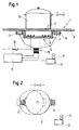
- a cooktop 1 according to FIG. 1 has a cooktop 3 made of glass ceramic circular cooking zone 4. To mark the cooking zone 4 on the hotplate 3 a known zone decor printed. Below the hotplate 3 is in the area the cooking zone 4 a known pot-shaped heating element 5 is arranged. This has a heating wire 9 arranged in an insulation pot 7. The heating wire 9 can be connected to mains voltage via a switch 10. To control the The hob 1 has a heating power or for setting the desired cooking level Control unit 11 on. The control unit 11 is also provided with a main switch 12 connected by which, as required by the relevant safety regulations, the hob 1 or all of its electrical consumers can be switched from the network.
- the hob 1 has display elements 13 which are in the form of seven-segment displays, Arranged in a manner known per se below the hotplate 3 in the hob 1 are.
- the power level is for the cooking zone 4 of the hob 1 "8" set and indicated by the seven-segment display 13.
- Isolation pot 7 are opposite each other in the form of metallic Electrodes a first sensor element 15 and a second sensor element 17 directly below the hotplate 3 arranged.
- the two sensor elements 15 and 17 are fed via a sensor circuit 19 or the control circuit 11 and their Capacities evaluated.
- a pot 21 exactly above the heating element 5.
- the setting of the desired The power level of the heating element 5 takes place according to FIG. 2 as follows:
- the position of the pot 21 according to FIG. 1 is shown in solid lines in FIG shown. In this position, the heating position, the pot 21 protrudes exactly the heating element 5. Both sensor elements 15 and 17 provide the information that in there is no pot 21 in their area. The power level already set "8" remains unchanged.
- the selection position detects the first Sensor element 15 that the pot 21 is not present.
- the sensor element 17 however, detects that the pot 21 is present.
- the pot 21 is therefore in the selection position.
- a time counter of the control unit 11 starts running. The heat setting will change approximately every 0.5 seconds increased by a cooking level and the increase is visualized by the display element 13.
- the power level is changed by turning the pot 21 and secondly from the position of the pot 21 in the cooking zone 4 directly to the desired one Cooking level of cooking zone 4 closed.
- the Pot has a magnetic element 25 in its bottom region.
- Below the Glass plate are the first sensor element 15 along a section of the The circumference of the cooking zone 4 arranged numerous reed switches.
Abstract
Description
Die vorliegende Erfindung betrifft ein Kochfeld mit einer Kochplatte mit zumindest einer Kochzone, die von einem in oder unterhalb der Kochplatte angeordneten Heizelement beheizbar ist, mit einer Bedieneinheit zur Vorgabe einer gewünschten Leistungsstufe des Heizelementes zum Beheizen eines auf der Kochplatte abgestellten Gargerätes, und weiterhin ein Verfahren zum Einstellen der Leistungsstufe eines Heizelementes eines Kochfeldes zum Beheizen eines in einer Kochzone auf einer Kochplatte abgestellten Gargerätes.The present invention relates to a hob with a hotplate with at least one Cooking zone by a heating element arranged in or below the hotplate is heated, with an operating unit for specifying a desired power level the heating element for heating a cooking appliance placed on the hotplate, and further a method for adjusting the power level of a heating element a hob for heating one placed in a cooking zone on a hotplate Cooking appliance.
Ein derartiges Kochfeld ist bekannt aus der Druckschrift DE 40 07 680 A1, wobei eine Heizplatte eines Glaskeramik-Elektroherdes mit mehreren eng nebeneinander liegenden Kochfeldelementen ausgestattet ist. Diese sind über Sensoren gesondert einschaltbar. Eine Steuerung der Heizplatte sorgt dafür, daß stets genau so viele der Kochfeldelemente eingeschaltet werden, wie von einem auf dem Kochfeld abgestellten Kochgeschirr, beispielsweise einem Topf, überdeckt oder nahezu überdeckt werden. Außerdem ist die Heizleistung der Kochfeldelemente unterschiedlich dergestalt eingestellt, daß durch ein Verschieben des Kochgeschirrs beispielsweise von einem Kochen auf höchster Temperatur auf eine niedrigere oder ganz niedrig eingestellte Temperatur gewechselt wird. Der Benutzer braucht also keine Schalter zu betätigen, um die Kochtemperatur entsprechend zu verändern, weil dies über die Sensoren und die erwähnte Einstellung der Steuerung der Heizplatte selbsttätig geschieht. Um die Temperatur des Kochgeschirrs zu ändern, muß dieses also lediglich auf der Fläche der Glaskeramikplatte zu anderen Kochfeldelementen verschoben werden. Diese sind von einer zentralen Steuerung des Herdes bereits auf die gewünschte andere Temperatur eingestellt. Beispielsweise sind die vorderen Kochfeldelemente der Heizplatte auf volle Temperatur eingestellt, die mittleren auf mittlere Temperatur und die hinteren Kochfeldelemente auf niedrige Temperatur. Man muß dann den betreffenden Kochtopf in diesem Beispiel nur von vorne über die Mitte nach hinter verschieben und durchläuft dann die erwähnten drei Kochstufen, nämlich Ankochen, Fortkochen und Warmhalten. Nachteilig an diesem Kochfeld ist insbesondere, daß die gewünschten Temperaturen weiterhin an der zentralen Steuerung des Herdes einzustellen sind, und daß der Platzbedarf auf dem Kochfeld für die verschiedenen Temperaturbereiche direkt von der Anzahl der realisierbaren Kochstufen abhängt. Weiterhin ist nachteilig, daß bei einer deutlichen Veränderung der Kochstufe das Gargerät über einen relativ großen Weg zu verschieben ist.Such a hob is known from DE 40 07 680 A1, one Heating plate of a glass ceramic electric cooker with several close to each other Hob elements is equipped. These can be switched on separately via sensors. A control of the heating plate ensures that exactly as many of the Cooktop elements can be switched on as if they were placed on the cooktop Cookware, for example a pot, are covered or almost covered. In addition, the heating power of the hob elements is set differently, that by moving the cookware, for example from cooking at the highest temperature to a lower or very low set temperature is changed. So the user does not need to operate a switch to Change the cooking temperature accordingly, because this is via the sensors and the mentioned Setting the control of the heating plate happens automatically. To the temperature to change the cookware, it only needs to be on the surface of the glass ceramic plate moved to other hob elements. These are from one central control of the cooker already at the desired different temperature set. For example, the front hob elements of the hot plate are full Temperature set, the middle to medium temperature and the rear hob elements to low temperature. You then have to put the saucepan in question in this Just move the example from the front over the middle to the back and then run through the three cooking levels mentioned, namely parboiling, continued cooking and keeping warm. A particular disadvantage of this hob is that the desired temperatures continue to be set at the central control of the cooker, and that the space requirement on the hob for the different temperature ranges directly from the number depends on the feasible cooking levels. Another disadvantage is that with a the cooking appliance changes significantly over a relatively large distance move is.
Aufgabe der vorliegenden Erfindung ist es, bei einem Kochfeld nach dem Oberbegriff des Patentanspruches 1 das Einstellen der Leistungsstufe eines Kochfeldes zu vereinfachen.The object of the present invention is in a hob according to the preamble of claim 1 to simplify the setting of the power level of a hob.
Erfindungsgemäß ist dies dadurch erreicht, daß bei einem Kochfeld nach dem Oberbegriff des Patentanspruches 1 das Gargerät selbst als die Bedieneinheit dient, und daß dazu der Kochzone eine Detektionseinrichtung zugeordnet ist, die aus einer Position bzw. Positionsänderung des Gargerätes im Bereich der Kochzone die gewünschte Leistungsstufe für diese Kochzone ableitet. Das erfindungsgemäße Verfahren zum Einstellen der Leistungsstufe ist dadurch gekennzeichnet, daß das Gargerät auf der Kochplatte im Bereich der Kochzone in ausgewählte Positionen geschoben wird, und daß aus der Anwesenheit des Gargerätes an diesen Positionen bzw aus dem Weg zu diesen Positionen die gewünschte Leistungsstufe ermittelt wird Zum Einstellen der gewünschten Leistungsstufe ist der Kochtopf lediglich im Bereich einer Kochzone, also räumlich eng begrenzt, zu bewegen. Trotz kurzer Verschiebewege für den Kochtopf ist eine feinstufige Leistungsabstufung beispielsweise in neun Leistungsstufen möglich. Zum Einstellen der Leistungsstufe ist der Topf höchstens geringfügig aus der betreffenden Heizzone zu verschieben und kann nach dem Einstellen der gewünschten Leistungsstufe wieder schnell zurückgeschoben werden, um wärmeübertragungstechnisch optimal über dem in oder unterhalb der Kochplatte angeordneten Heizelement positioniert zu sein. Gegebenenfalls kann die Detektionseinrichtung auch an einer dem Kochfeld zugeordneten Dunstabzugshaube vorgesehen sein. According to the invention this is achieved in that with a hob according to the preamble of claim 1, the cooking device itself serves as the control unit, and that for this purpose the cooking zone is assigned a detection device, which from one position or change the position of the cooking appliance in the area of the cooking zone Power level for this cooking zone. The inventive method for Setting the power level is characterized in that the cooking device on the Hotplate is pushed into selected positions in the cooking zone, and that from the presence of the cooking device at these positions or out of the way the desired power level is determined for these positions desired power level, the saucepan is only in the area of a cooking zone, ie limited space to move. Despite the short displacement of the saucepan A fine-graded performance gradation is possible, for example, in nine performance levels. To set the power level, the pot is at most slightly out of the one in question Heating zone can move and after setting the desired Power level can be quickly pushed back to heat transfer technology optimally above the heating element arranged in or below the hotplate to be positioned. If necessary, the detection device can also be connected to a Cooker hood associated with the hob can be provided.
Vorteilhafterweise weist die Detektionseinrichtung zumindest zwei im Randbereich der Kochzone angeordnete und sich im wesentlichen gegenüberliegende Sensorelemente auf. Diese detektieren die Anwesenheit oder Abwesenheit des Gargerätes und ermitteln in Abhängigkeit von der Zeit dieser Anwesenheit oder Abwesenheit des Gargerätes am Ort der Sensorelemente die gewünschte Leistungsstufe. Als Sensorelemente können im Prinzip an sich bekannte Topferkennungselemente dienen, wie beispielsweise kapazitive, induktive oder optische Elemente. Zum Verstellen der Leistungsstufe wird der Topf beispielsweise von einem der beiden Topferkennungselemente weggezogen und damit auf das andere Topferkennungselement geschoben. Dies setzt voraus, daß der Abstand der Topferkennungselemente größer ist als der Durchmesser des Topfbodens. Aus der Richtung der Topfbewegung und der Dauer des Verbleibens des Topfes über dem einen oder anderen Sensorelement ermittelt eine Steuereinheit des Kochfeldes die gewünschte Leistungsstufe der entsprechenden Kochzone. Alternativ kann zur Positionserkennung des Topfes dieser zwei Sensorelemente aufweisen und das Kochfeld lediglich ein korrespondierendes Sensorelement. Dazu sind jedoch besonders gestaltete Kochtöpfe erforderlich.The detection device advantageously has at least two in the edge region of the Cooking zone arranged and essentially opposite sensor elements on. These detect and determine the presence or absence of the cooking device depending on the time of this presence or absence of the cooking appliance the desired power level at the location of the sensor elements. As sensor elements can serve in principle known pot detection elements, such as capacitive, inductive or optical elements. To adjust the power level the pot is pulled away from one of the two pot detection elements, for example and thus pushed onto the other pan detection element. This requires, that the distance between the pot detection elements is larger than the diameter the bottom of the pot. From the direction of the pot movement and the duration of the stay a control unit determines the pot over one or the other sensor element the desired power level of the corresponding cooking zone. Alternatively can have these two sensor elements for position detection of the pot and the cooktop only a corresponding sensor element. To do this, however specially designed pots are required.
Andererseits ist es auch möglich, daß die Detektionseinrichtung zumindest zwei Sensorelemente aufweist, die den jeweiligen Abstand zum Gargerät detektieren und daraus die für die betreffende Kochzone gewünschte Leistungsstufe ableiten. Es ist einerseits möglich, daß der größere Abstand von einer der beiden Sensorelemente als Erhöhungs- oder Erniedrigungskriterium für die Leistungsstufe verwendet wird und mit zunehmender Dauer des Stehens des Topfes in dieser Stellung die Leistung entsprechend geändert wird. Andererseits ist es auch möglich, daß unmittelbar aus den unterschiedlichen Abständen auf eine gewünschte Leistungsstufe geschlossen wird. Dies ist jedoch meßtechnisch relativ aufwendigOn the other hand, it is also possible for the detection device to have at least two sensor elements has, which detect the respective distance to the cooking appliance and from it derive the power level required for the relevant cooking zone. It is on the one hand possible that the larger distance from one of the two sensor elements is used as an increase or decrease criterion for the power level and with increasing duration of standing of the pot in this position the performance accordingly will be changed. On the other hand, it is also possible that directly from the different Distances to a desired performance level is concluded. This is however, it is relatively expensive to measure
Gemäß einer bevorzugten Ausführungsform weist die Detektionseinrichtung ein berührungslos arbeitendes Sensorelement auf, daß unterhalb der Kochplatte angeordnet ist. Entsprechend der Technik zur Topferkennung ist dadurch eine sichere Erkennung der gewünschten Leistungsstufe möglich ohne störende Elemente oberhalb der Kochplatte. Alternativ könnte beispielsweise oberhalb der Kochplatte ein Sensorelement angeordnet sein, das die von der Topfwand abgestrahlte Wärmestrahlung in an sich bekannter Weise detektiert. An der Topfaußenwand ist umfangsseitig eine entsprechend strukturierte Schicht angeordnet. Diese weist umfangsseitig abwechselnd Zonen großen und kleinen Emissionsfaktors auf. Dadurch kann die Sensorik beispielsweise den Drehwinkel eines auf der Kochzone entsprechend einer Bedienhandhabe gedrehten Topfes ermitteln und daraus die gewünschte Leistungsstufe abgeleitet werden.According to a preferred embodiment, the detection device has a contactless working sensor element that is arranged below the hotplate. According to the technology for pot detection, a reliable detection of the Desired power level possible without disruptive elements above the hotplate. Alternatively, for example, a sensor element could be located above the hotplate be arranged, the radiated heat radiation from the pot wall in itself detected in a known manner. On the outer wall of the pot there is a corresponding one on the circumference structured layer arranged. This shows alternately on the circumference Zones of large and small emission factor. This allows the sensors For example, the angle of rotation corresponding to one on the cooking zone Determine the operating handle of the rotated pot and use it to determine the desired one Performance level can be derived.
Um die thermischen Anforderungen an die Sensorelemente der Detektionseinrichtung reduzieren zu können, sind diese unterhalb der Kochplatte außerhalb einer Wärmeisolation eines an sich bekannten Heizelementes der Kochzone angeordnet. Weiterhin ist in diesem Bereich sichergestellt, daß bei Verwendung einer Kochfeldplatte aus Glaskeramikmaterial diese aufgrund der geringeren Temperaturen in diesem Bereich als Nichtleiter gilt. Deshalb ist in diesem Falle eine zusätzliche Isolation einer metallischen Meßelektrode eines beispielsweise kapazitiven Topfdetektors als zusätzliche elektrische Schutzmaßnahme nicht erforderlich.To meet the thermal requirements for the sensor elements of the detection device To be able to reduce, these are below the hotplate outside of thermal insulation a known heating element of the cooking zone. Still is in this area ensures that when using a hob made of glass ceramic material this due to the lower temperatures in this area than Non-conductor applies. Therefore, in this case, additional insulation is a metallic Measuring electrode of a capacitive pot detector, for example, as an additional electrical one Protective measure not required.
Um eine Fehlbedienung des Kochfeldes auszuschließen, weißt die Detektionseinrichtung eine Prüfeinrichtung auf, die kurzzeitige bzw. unbeabsichtigte Positionen bzw. Positionsänderungen des Gargerätes als solche erkennt und die Leistungsstufe unverändert läßt. Entsprechendes wird ebenfalls erreicht, wenn die Prüfeinrichtung langzeitige, unbeabsichtigte Positionen bzw. Positionsänderungen des Gargerätes als solche erkennt und die Leistungsstufe unverändert läßt. Typischerweise sollte eine korrekte Betätigung bzw. Einstellung der Heizstufe durch das Gargerät länger als etwa eine Sekunde und kürzer als etwa zehn Sekunden dauern. Dadurch ist auch ein Schutz vor Fehlbedienung beim Wischen zu Reinigungszwecken über die Sensorik der Detektionseinrichtung und beim unbeabsichtigten Ablegen beispielsweise eines Bestecks realisiert.The detection device knows to rule out incorrect operation of the hob a test facility that detects short-term or unintended positions or Detects changes in position of the cooking appliance as such and the power level unchanged leaves. The same is also achieved if the test facility has long-term, unintended positions or changes in position of the cooking appliance as such recognizes and leaves the power level unchanged. Typically, a correct one Operation or setting of the heating level by the cooking device for longer than about one second and last less than about ten seconds. This also provides protection against Incorrect operation when wiping for cleaning purposes via the sensors of the detection device and realized in the event of unintentional placement of cutlery, for example.
Nachfolgend sind anhand schematischer Darstellungen zwei Ausführungsbeispiele des erfindungsgemäßen Kochfeldes beschrieben.Below are two exemplary embodiments of the described hob of the invention.
Es zeigen:
- Fig. 1
- in einer stark schematisierten Seitendarstellung das erfindungsgemäße Kochfeld gemäß dem ersten Ausführungsbeispiel,
- Fig. 2
- in einer Draufsicht stark vereinfacht die Darstellung gemäß Figur 1 und
- Fig. 3
- in einer Draufsicht stark vereinfacht das zweite Ausführungsbeispiel.
- Fig. 1
- the hob according to the invention according to the first embodiment in a highly schematic side view,
- Fig. 2
- in a top view, the illustration according to FIGS. 1 and 2 is greatly simplified
- Fig. 3
- the second embodiment is greatly simplified in a plan view.
Ein Kochfeld 1 gemäß Figur 1 weist eine Kochplatte 3 aus Glaskeramik mit einer
kreisförmigen Kochzone 4 auf. Zur Markierung der Kochzone 4 ist auf die Kochplatte 3
ein an sich bekanntes Zonendekor gedruckt. Unterhalb der Kochplatte 3 ist im Bereich
der Kochzone 4 ein an sich bekanntes topfförmiges Heizelement 5 angeordnet. Dieses
weist einen in einem Isolationstopf 7 angeordneten Heizdraht 9 auf. Der Heizdraht 9
kann über einen Schalter 10 an Netzspannung gelegt werden. Zur Steuerung der
Heizleistung bzw. zum Einstellen der gewünschten Kochstufe weist das Kochfeld 1 eine
Steuereinheit 11 auf. Weiterhin ist die Steuereinheit 11 mit einem Hauptschalter 12
verbunden, durch den, wie von den einschlägigen Sicherheitsvorschriften gefordert,
das Kochfeld 1 bzw. all dessen elektrische Verbraucher vom Netz schaltbar sind. Auch
verfügt das Kochfeld 1 über Anzeigeelemente 13, die in Form von Siebensegmentanzeigen,
in an sich bekannter Weise unterhalb der Kochplatte 3 im Kochfeld 1 angeordnet
sind. Gemäß Figur 1 ist für die Kochzone 4 des Kochfeldes 1 die Leistungsstufe
"8" eingestellt und durch die Siebensegment-Anzeige 13 angezeigt. Außerhalb des
Isolationstopfes 7 sind sich einander gegenüberliegend in Form von metallischen
Elektroden ein erstes Sensorelement 15 und ein zweites Sensorelement 17 direkt unterhalb
der Kochplatte 3 angeordnet. Die beiden Sensorelemente 15 und 17 werden
über eine Sensorschaltung 19 bzw. die Steuerschaltung 11 gespeist und deren
Kapazitäten ausgewertet. Im Bereich der Kochzone 4 ist auf der Kochplatte gemäß
Figur 1 exakt über dem Heizelement 5 ein Topf 21 abgestellt. Die Einstellung der gewünschten
Leistungsstufe des Heizelementes 5 erfolgt gemäß Figur 2 wie folgt:A cooktop 1 according to FIG. 1 has a
Mit durchgezogenen Linien ist in Figur 2 die Stellung des Topfes 21 gemäß Figur 1
dargestellt. In dieser Position, der Beheizungsposition, steht der Topf 21 exakt über
dem Heizelement 5. Beide Sensorelemente 15 und 17 liefern die Information, daß in
ihrem Bereich kein Topf 21 vorhanden ist. Die bereits davor eingestellte Leistungsstufe
"8" bleibt unverändert. Durch das Verschieben des Topfes 21 in die Position, in der der
Topf mit unterbrochenen Linien dargestellt ist, der Auswahlposition, detektiert das erste
Sensorelement 15, daß der Topf 21 nicht vorhanden ist. Das Sensorelement 17
detektiert hingegen, daß der Topf 21 vorhanden ist. Der Topf 21 befindet sich also in
der Auswahlposition. Mit der ersten Detektion des Topfes 21 in der Auswahlposition
läuft ein Zeitzähler der Steuereinheit 11 los. Etwa alle 0,5 Sekunden wird die Kochstufe
um eine Kochstufe erhöht und die Erhöhung durch das Anzeigeelement 13 visualisiert.
Ist die Bedienperson mit der angezeigten Heizstufe einverstanden, schiebt sie den
Topf 21 wieder in die Beheizungsposition gemäß Figur 1 zurück. Detektiert eines der
beiden Sensorelemente 15 oder 17 eine Anwesenheit des Topfes 21 von kürzer als
etwa eine Sekunde oder länger als etwa zehn Sekunden, wird durch das Blinken des
Anzeigeelementes 13 der Bedienperson ein Fehler angezeigt und zugleich die Heizleistung
der entsprechenden Kochzone 4 abgeschaltet.The position of the
Alternativ dazu können die beiden Sensorelemente 15 und 17 auch im Inneren des
Isolationstopfes 7 des Heizelementes 5 unterhalb des Kochtopfes 21 angeordnet sein.
In der Topfstellung gemäß Figur 1, der Beheizungsposition, würden dann zunächst
beide Sensorelemente 15 und 17 die Anwesenheit des Topfes 21 detektieren und die
Leistungsstufe unverändert lassen. Sobald eines der Sensorelemente 15 oder 17 das
Entfernen des Topfes detektiert und das andere gleichzeitig seine Anwesenheit detektiert,
würde entsprechend dem oben beschriebenen Vorgang die Leistungsstufe in Abhängigkeit
von der Bewegungsrichtung des Topfes 21 entsprechend schrittweise erhöht
oder verringert. Zusätzlich kann für Geschirr, dessen Anwesenheit oder Position
nur sehr aufwendig nachweisbar ist, beispielsweise für ein Glasgefäß, eine zusätzliche
nicht näher dargestellte herkömmliche Bedieneinheit vorgesehen sein.Alternatively, the two
Zur Beschreibung des zweiten Ausführungsbeispiels werden aus Vereinfachungsgründen
in Fig. 3 dieselben Bezugszeichen verwendet. In Abwandlung des ersten Ausführungsbeispieles
wird erstens die Leistungsstufe durch Drehen des Topfes 21 verändert
und zweitens aus der Position des Topfes 21 in der Kochzone 4 direkt auf die gewünschte
Kochstufe der Kochzone 4 geschlossen. Dies ist dadurch erreicht, daß der
Topf in seinem Bodenbereich ein Magnetelement 25 aufweist. Unterhalb der
Glasplatte sind als erstes Sensorelement 15 entlang eines Teilabschnittes des
Umfanges der Kochzone 4 zahlreiche Reedschalter angeordnet. Durch Drehen des
exakt über dem Heizelement abgestellten Topfes 21 im Uhrzeigersinn passiert das
Magnetelement 25 nacheinander die verschiedenen Reedschalter 15. Diese
Bewegung des Topfes 21 rechnen die Sensorschaltung 19 sowie die Steuereinheit 11
unmittelbar in die gewünschte Heizstufe um. Dabei entspricht beispielsweise eine
"Sechs-Uhr-Position" des Magnetelementes 25 bzw. des Topfes 21 einer mittleren
Koch- bzw. Leistungsstufe.To simplify the description of the second exemplary embodiment,
the same reference numerals are used in FIG. 3. In a modification of the first embodiment
First, the power level is changed by turning the
Claims (10)
Applications Claiming Priority (2)
| Application Number | Priority Date | Filing Date | Title |
|---|---|---|---|
| DE19825321 | 1998-06-05 | ||
| DE1998125321 DE19825321C1 (en) | 1998-06-05 | 1998-06-05 | Hob with control unit for specifying the power level and method for setting the power level of a heating element of a hob |
Publications (2)
| Publication Number | Publication Date |
|---|---|
| EP0967839A2 true EP0967839A2 (en) | 1999-12-29 |
| EP0967839A3 EP0967839A3 (en) | 2001-10-31 |
Family
ID=7870120
Family Applications (1)
| Application Number | Title | Priority Date | Filing Date |
|---|---|---|---|
| EP99110681A Withdrawn EP0967839A3 (en) | 1998-06-05 | 1999-06-02 | Cooking plate with operating unit determining its power level |
Country Status (2)
| Country | Link |
|---|---|
| EP (1) | EP0967839A3 (en) |
| DE (1) | DE19825321C1 (en) |
Cited By (10)
| Publication number | Priority date | Publication date | Assignee | Title |
|---|---|---|---|---|
| EP1344983A2 (en) | 2002-03-13 | 2003-09-17 | Cherry GmbH | Arrangement for the control of a cooking hob |
| EP1758431A2 (en) | 2005-08-23 | 2007-02-28 | E.G.O. ELEKTRO-GERÄTEBAU GmbH | Electronicallly controlled cooktop with several cooking fields and the controlling method of such cooking fields |
| WO2008055370A1 (en) * | 2006-11-09 | 2008-05-15 | Menu-System Ag | Method for controlling an induction cooking appliance and induction cooking appliance |
| WO2009024899A2 (en) * | 2007-08-21 | 2009-02-26 | Koninklijke Philips Electronics N.V. | Induction heating appliance |
| EP2276322A1 (en) | 2009-07-16 | 2011-01-19 | E.G.O. ELEKTRO-GERÄTEBAU GmbH | Method for operating a hotplate |
| EP2741010A1 (en) * | 2012-12-05 | 2014-06-11 | Electrolux Home Products Corporation N.V. | A cooking hob including a user interface |
| EP2527747B1 (en) * | 2011-05-24 | 2018-01-03 | Diehl AKO Stiftung & Co. KG | Device for operating a hotplate |
| EP3855868A1 (en) * | 2020-01-22 | 2021-07-28 | E.G.O. Elektro-Gerätebau GmbH | Method for controlling the power supplied to an induction heating coil of an induction hob and induction hob |
| EP4067749A4 (en) * | 2019-11-28 | 2023-11-29 | LG Electronics Inc. | Electric cooker providing specific functions according to gestures of user |
| EP4067748A4 (en) * | 2019-11-25 | 2024-02-28 | Lg Electronics Inc | Electric cooker providing specific functions without user intervention |
Families Citing this family (5)
| Publication number | Priority date | Publication date | Assignee | Title |
|---|---|---|---|---|
| DE102004011749A1 (en) * | 2004-03-02 | 2005-09-15 | E.G.O. Elektro-Gerätebau GmbH | A method for controlling heating zones of a hob unit has inductive heating elements and sensing elements to select a zone for use and a single heating level control switch for all zones |
| DE102004016631A1 (en) * | 2004-03-29 | 2005-11-10 | E.G.O. Elektro-Gerätebau GmbH | A method for controlling the temperature of a cooking vessel on a cooker hob unit has a ring of four capacitive sensors around the perimeter of the heating unit |
| DE102004059822B4 (en) * | 2004-12-03 | 2011-02-24 | E.G.O. Elektro-Gerätebau GmbH | Method for operating an induction hob |
| DE102009020905A1 (en) | 2009-05-12 | 2010-12-09 | Diehl Ako Stiftung & Co. Kg | Hob for use in cookware, has multiple heating elements, which are arranged in or below hot plate for cooking zone, such that each heating element is assigned detection unit for pan detection |
| DE102011102394B4 (en) * | 2011-05-24 | 2013-01-31 | Diehl Ako Stiftung & Co. Kg | Device and method for operating a hob |
Citations (1)
| Publication number | Priority date | Publication date | Assignee | Title |
|---|---|---|---|---|
| DE4007680A1 (en) | 1990-03-10 | 1991-09-19 | Grass Ag | Glass-ceramic cooking hob - has field of sensor-driven elements each a preset different power outputs |
Family Cites Families (4)
| Publication number | Priority date | Publication date | Assignee | Title |
|---|---|---|---|---|
| DE3209260A1 (en) * | 1982-03-13 | 1983-09-22 | Bosch-Siemens Hausgeräte GmbH, 7000 Stuttgart | Cooking hob made of glass-ceramic material |
| DE3804170A1 (en) * | 1987-04-06 | 1989-08-24 | Kueppersbusch | Cooking apparatus |
| FR2667477A1 (en) * | 1990-09-28 | 1992-04-03 | Philips Electronique Lab | HOT TABLE WITH AUTOMATIC CONTROLS. |
| EP0620698A1 (en) * | 1993-04-13 | 1994-10-19 | Whirlpool Europe B.V. | Device for detecting the presence of a food container, such as a saucepan, dish or the like, on a glass ceramic cooking hob |
-
1998
- 1998-06-05 DE DE1998125321 patent/DE19825321C1/en not_active Expired - Fee Related
-
1999
- 1999-06-02 EP EP99110681A patent/EP0967839A3/en not_active Withdrawn
Patent Citations (1)
| Publication number | Priority date | Publication date | Assignee | Title |
|---|---|---|---|---|
| DE4007680A1 (en) | 1990-03-10 | 1991-09-19 | Grass Ag | Glass-ceramic cooking hob - has field of sensor-driven elements each a preset different power outputs |
Cited By (18)
| Publication number | Priority date | Publication date | Assignee | Title |
|---|---|---|---|---|
| EP1344983A2 (en) | 2002-03-13 | 2003-09-17 | Cherry GmbH | Arrangement for the control of a cooking hob |
| EP1344983A3 (en) * | 2002-03-13 | 2006-04-19 | Cherry GmbH | Arrangement for the control of a cooking hob |
| EP1758431A2 (en) | 2005-08-23 | 2007-02-28 | E.G.O. ELEKTRO-GERÄTEBAU GmbH | Electronicallly controlled cooktop with several cooking fields and the controlling method of such cooking fields |
| EP1758431A3 (en) * | 2005-08-23 | 2009-01-07 | E.G.O. ELEKTRO-GERÄTEBAU GmbH | Electronicallly controlled cooktop with several cooking fields and the controlling method of such cooking fields |
| WO2008055370A1 (en) * | 2006-11-09 | 2008-05-15 | Menu-System Ag | Method for controlling an induction cooking appliance and induction cooking appliance |
| CN101574014B (en) * | 2006-11-09 | 2012-04-11 | 菜单-系统股份公司 | Method for controlling an induction cooking appliance and induction cooking appliance |
| WO2009024899A2 (en) * | 2007-08-21 | 2009-02-26 | Koninklijke Philips Electronics N.V. | Induction heating appliance |
| WO2009024899A3 (en) * | 2007-08-21 | 2009-04-30 | Koninkl Philips Electronics Nv | Induction heating appliance |
| DE102009034203A1 (en) | 2009-07-16 | 2011-01-20 | E.G.O. Elektro-Gerätebau GmbH | Method for operating a hob |
| EP2276322A1 (en) | 2009-07-16 | 2011-01-19 | E.G.O. ELEKTRO-GERÄTEBAU GmbH | Method for operating a hotplate |
| EP2527747B1 (en) * | 2011-05-24 | 2018-01-03 | Diehl AKO Stiftung & Co. KG | Device for operating a hotplate |
| EP2741010A1 (en) * | 2012-12-05 | 2014-06-11 | Electrolux Home Products Corporation N.V. | A cooking hob including a user interface |
| WO2014086566A1 (en) * | 2012-12-05 | 2014-06-12 | Electrolux Home Products Corporation N. V. | A cooking hob including a user interface |
| US9557064B2 (en) | 2012-12-05 | 2017-01-31 | Electrolux Home Products Corporation N.V. | Cooking hob including a user interface |
| CN105051460B (en) * | 2012-12-05 | 2017-07-07 | 伊莱克斯家用产品股份有限公司 | Cooking hob and its operating method including user interface |
| EP4067748A4 (en) * | 2019-11-25 | 2024-02-28 | Lg Electronics Inc | Electric cooker providing specific functions without user intervention |
| EP4067749A4 (en) * | 2019-11-28 | 2023-11-29 | LG Electronics Inc. | Electric cooker providing specific functions according to gestures of user |
| EP3855868A1 (en) * | 2020-01-22 | 2021-07-28 | E.G.O. Elektro-Gerätebau GmbH | Method for controlling the power supplied to an induction heating coil of an induction hob and induction hob |
Also Published As
| Publication number | Publication date |
|---|---|
| DE19825321C1 (en) | 2000-02-10 |
| EP0967839A3 (en) | 2001-10-31 |
Similar Documents
| Publication | Publication Date | Title |
|---|---|---|
| DE3744372C2 (en) | Power control method for protecting glass ceramic cooking surfaces | |
| DE4022846C2 (en) | Device for power control and limitation in a heating surface made of glass ceramic or a comparable material | |
| EP0967839A2 (en) | Cooking plate with operating unit determining its power level | |
| EP0442275B1 (en) | Device for detecting a vessel put in the heating zone of a cooking or heating apparatus | |
| DE4130337C2 (en) | Method for operating an electric heating unit and electric heating unit | |
| DE3837096C2 (en) | Power control arrangement for a glass ceramic hob | |
| EP2153698B1 (en) | Control method for a hob and hob for carrying out said method | |
| EP3196555B1 (en) | Hob with a glass ceramic cooking plate | |
| DE19918290C1 (en) | Cooking appliance with several cooking zones has cooking zone selector elements and operating state selector elements with control device for two-step setting of cooking program | |
| DE69834791T2 (en) | HEATING ELEMENT | |
| EP0690659B1 (en) | Infrared beam controlled cooking unit | |
| AT389612B (en) | ELECTRIC RADIATION HEATING UNIT | |
| DE4345472C2 (en) | Method for preparing dishes in a cookware at least partially filled with water on a ceramic hob, in particular glass ceramic | |
| EP0374868A1 (en) | Cooking hob | |
| EP2258987A2 (en) | Household device with a touch screen | |
| EP1217873B1 (en) | Temperature of cooking vessels sensing method and device | |
| DE3117205A1 (en) | Optoelectronic cooking panel controller | |
| EP0780081B2 (en) | Method for the automatic regulation of heatable cooking surfaces | |
| DE3934157C2 (en) | Hob | |
| DE60201683T2 (en) | COOKER | |
| DE4413979C2 (en) | Sensor-controlled cooking unit and cooking device | |
| EP1255420B1 (en) | Display device | |
| DE102004059822B4 (en) | Method for operating an induction hob | |
| DE19610073A1 (en) | Ceramic glass cooking hob | |
| EP0806887A1 (en) | Method and device for recognizing the stage of cooking of cooked food |
Legal Events
| Date | Code | Title | Description |
|---|---|---|---|
| PUAI | Public reference made under article 153(3) epc to a published international application that has entered the european phase |
Free format text: ORIGINAL CODE: 0009012 |
|
| AK | Designated contracting states |
Kind code of ref document: A2 Designated state(s): AT BE CH CY DE DK ES FI FR GB GR IE IT LI LU MC NL PT SE |
|
| AX | Request for extension of the european patent |
Free format text: AL;LT;LV;MK;RO;SI |
|
| PUAL | Search report despatched |
Free format text: ORIGINAL CODE: 0009013 |
|
| AK | Designated contracting states |
Kind code of ref document: A3 Designated state(s): AT BE CH CY DE DK ES FI FR GB GR IE IT LI LU MC NL PT SE |
|
| AX | Request for extension of the european patent |
Free format text: AL;LT;LV;MK;RO;SI |
|
| STAA | Information on the status of an ep patent application or granted ep patent |
Free format text: STATUS: THE APPLICATION HAS BEEN WITHDRAWN |
|
| 18W | Application withdrawn |
Withdrawal date: 20020306 |