EP0658067A1 - Control for evaluating sensor signals of domestic appliances - Google Patents
Control for evaluating sensor signals of domestic appliances Download PDFInfo
- Publication number
- EP0658067A1 EP0658067A1 EP94117875A EP94117875A EP0658067A1 EP 0658067 A1 EP0658067 A1 EP 0658067A1 EP 94117875 A EP94117875 A EP 94117875A EP 94117875 A EP94117875 A EP 94117875A EP 0658067 A1 EP0658067 A1 EP 0658067A1
- Authority
- EP
- European Patent Office
- Prior art keywords
- control
- temperature
- glass ceramic
- sensor signals
- control system
- Prior art date
- Legal status (The legal status is an assumption and is not a legal conclusion. Google has not performed a legal analysis and makes no representation as to the accuracy of the status listed.)
- Ceased
Links
Images

Classifications
-
- H—ELECTRICITY
- H05—ELECTRIC TECHNIQUES NOT OTHERWISE PROVIDED FOR
- H05B—ELECTRIC HEATING; ELECTRIC LIGHT SOURCES NOT OTHERWISE PROVIDED FOR; CIRCUIT ARRANGEMENTS FOR ELECTRIC LIGHT SOURCES, IN GENERAL
- H05B3/00—Ohmic-resistance heating
- H05B3/68—Heating arrangements specially adapted for cooking plates or analogous hot-plates
- H05B3/74—Non-metallic plates, e.g. vitroceramic, ceramic or glassceramic hobs, also including power or control circuits
- H05B3/746—Protection, e.g. overheat cutoff, hot plate indicator
-
- G—PHYSICS
- G05—CONTROLLING; REGULATING
- G05D—SYSTEMS FOR CONTROLLING OR REGULATING NON-ELECTRIC VARIABLES
- G05D23/00—Control of temperature
- G05D23/19—Control of temperature characterised by the use of electric means
- G05D23/20—Control of temperature characterised by the use of electric means with sensing elements having variation of electric or magnetic properties with change of temperature
- G05D23/24—Control of temperature characterised by the use of electric means with sensing elements having variation of electric or magnetic properties with change of temperature the sensing element having a resistance varying with temperature, e.g. a thermistor
-
- H—ELECTRICITY
- H05—ELECTRIC TECHNIQUES NOT OTHERWISE PROVIDED FOR
- H05B—ELECTRIC HEATING; ELECTRIC LIGHT SOURCES NOT OTHERWISE PROVIDED FOR; CIRCUIT ARRANGEMENTS FOR ELECTRIC LIGHT SOURCES, IN GENERAL
- H05B2213/00—Aspects relating both to resistive heating and to induction heating, covered by H05B3/00 and H05B6/00
- H05B2213/05—Heating plates with pan detection means
-
- H—ELECTRICITY
- H05—ELECTRIC TECHNIQUES NOT OTHERWISE PROVIDED FOR
- H05B—ELECTRIC HEATING; ELECTRIC LIGHT SOURCES NOT OTHERWISE PROVIDED FOR; CIRCUIT ARRANGEMENTS FOR ELECTRIC LIGHT SOURCES, IN GENERAL
- H05B2213/00—Aspects relating both to resistive heating and to induction heating, covered by H05B3/00 and H05B6/00
- H05B2213/07—Heating plates with temperature control means
Definitions
- the invention relates to a controller for household appliances for evaluating sensor signals, in particular for radiant heating under glass ceramic cooktops.
- Glass ceramic hobs are usually equipped with four hobs that can be operated using radiant heating.
- the materials currently used, from which glass ceramics are made, are characterized by poor thermal conductivity transverse to the radiation direction of the radiant heaters, which is due to the fact that glass and glass-related materials are solid-state ion conductors.
- the permeability to radiant heat from the infrared transmitter is sufficiently optimized for the transmission characteristics of the respective glass ceramic and the expected cooking processes.
- the usual operating temperatures of the glass ceramic for cooking processes of the respective hotplate, which requires radiant heating are in a temperature range from 300 ° C to 500 ° C. Depending on these temperatures, physical values of the glass ceramic change, for example the specific thermal conductivity, the specific electrical resistance and capacitive behaviors. Glass ceramic cooktops are permanently damaged if they are operated on the idle side, ie without or with empty pots. It is therefore necessary to avoid these operating conditions for life and energy reasons as far as possible.
- a radiant heater 1, a glass ceramic cooktop section 2, a cooking vessel 3 with items to be cooked 4 and an energy flow direction 5 from the radiation source 1 can be seen directed towards the glass ceramic cooktop surface 2.
- the thermal energy generated in the heating element 1 is conducted essentially as infrared radiation through the glass ceramic 2 to the bottom of the pot, where it is converted into heat.
- the glass ceramic heats up in part. by absorbing part of the continuous infrared radiation and partly by convection of the air in the trough.
- the glass ceramic is cooled by heat dissipation in the bottom of the pot, which is on the trough.
- the heat finally reached in the pot 3 is dissipated from the pot 3 into the environment by the evaporation of liquid from the food 4. Further heat losses are given by the infrared radiation from the pot walls or the pot lid and by heat conduction.
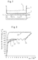
- the course of the curve approximates the course according to curve 25. It can therefore be deduced from the glass ceramic cooking surface temperature whether the pot is empty, whether the pot contents are overcooking or whether normal cooking is taking place.
- the pan detection is carried out safely in the interval of two to four minutes for each cooking point of the glass ceramic hob that is switched on.
- the detection of the temperature of the glass ceramic hob can be detected in a direct and indirect way.
- the measurement method brought about by temperature sensors and thermocouples can be called a direct measurement of the temperature. To do this, the temperature sensor must be shadowed against direct infrared radiation from the heating element.
- K is a trace geometry constant
- B is a reference temperature in degrees Kelvin
- T is the real temperature in degrees Kelvin.
- the contact strips are to be arranged in an arrangement on the glass ceramic, which rules out mutual interference between the temperature sensors of different hotplates of the same glass ceramic hob.
- FIG. 3 essentially shows the measuring point tapping points 6, 8, 9 and 10 as well as the ground line 7, which is arranged so as to be meaningfully enveloping.
- Link 11 is created and used as an input variable for an astable multivibrator 12.
- a signal path that is processed via a downstream pulse shaper (not shown) leads to an evaluation circuit 13, which decodes the changes in resistance as a temperature profile.
- the temperature-dependent, complex resistance of a sensor-monitored glass ceramic hob section determined by means of a sensor is arranged according to FIG. 4 as a frequency-determining unit of a frequency generator.
- the frequency generated is indirectly proportional to the resistance of the glass ceramic.
- the controller which converts the pulse frequency generated by an evaluation circuit into a corresponding glass ceramic cooktop temperature, now carries out a target / actual temperature comparison of characteristic temperature profiles according to FIG. 2.
- a pot-type detection of a basic type is carried out, improper pot placement is recognized, an empty-cooked pot is detected and an optical or acoustic signal can be arranged for the case of pot-detection.
- the control detects an empty or non-existent pot on the hotplate of the glass ceramic cooktop, it switches off the energy supply. Since the control system can detect the beginning of cooking processes in accordance with the target / actual value comparison of characteristic temperature profiles, the energy supply is regulated in accordance with the state of the food.
- the relatively inexpensive and easily releasable method can detect idling after just two to four minutes, the detection options being that the cooking vessel is not placed exactly and an early one Cooking of food in cooking vessels can also be done using this pan detection method.
Landscapes
- Engineering & Computer Science (AREA)
- Chemical & Material Sciences (AREA)
- Ceramic Engineering (AREA)
- Physics & Mathematics (AREA)
- General Physics & Mathematics (AREA)
- Automation & Control Theory (AREA)
- Electric Stoves And Ranges (AREA)
- Cookers (AREA)
Abstract
Description
Die Erfindung bezieht sich auf eine Steuerung für Haushaltgeräte zur Auswertung von Sensorsignalen, insbesondere für Strahlungsheizungen unter Glaskeramik-Kochflächen.The invention relates to a controller for household appliances for evaluating sensor signals, in particular for radiant heating under glass ceramic cooktops.
Glaskeramik-Kochflächen sind mit üblicherweise vier Kochstellen ausgestattet, die durch Strahlungsheizungen betrieben werden können. Die derzeitig verwendeten Materialien, aus denen Glaskeramiken bestehen, sind durch eine schlechte Wärmeleitfähigkeit quer zur Strahlungsrichtung der Strahlungsheizungen gekennzeichnet, was seine Ursache darin hat, daß Glas und glasverwandte Materialien Festkörper-Ionenleiter darstellen. Die Durchlässigkeit für Strahlungswärme der Infrarotsender ist hinreichend optimiert zur Durchlaßcharakteristik der jeweiligen Glaskeramik und den zu erwartenden Kochvorgängen angepaßt. Die auftretenden üblichen Betriebstemperaturen der Glaskeramik für Kochvorgänge der jeweiligen Kochstelle, die eine Strahlungsheizung voraussetzt, liegt in einem Temperaturbereich von 300°C bis 500°C. In Abhängigkeit von diesen Temperaturen verändern sich physikalische Werte der Glaskeramik, beispielsweise die spezifische Wärmeleitfähigkeit, der spezifische elektrische Widerstand und kapazitive Verhaltensweisen. Glaskeramik-Kochflächen nehmen auf Dauer Schaden, wenn sie leerlaufseitig, d.h. ohne oder mit leeren Töpfen, betrieben werden. Es ist daher notwendig, diese Betriebszustände aus Lebensdauer und energetischen Gründen möglichst zu vermeiden.Glass ceramic hobs are usually equipped with four hobs that can be operated using radiant heating. The materials currently used, from which glass ceramics are made, are characterized by poor thermal conductivity transverse to the radiation direction of the radiant heaters, which is due to the fact that glass and glass-related materials are solid-state ion conductors. The permeability to radiant heat from the infrared transmitter is sufficiently optimized for the transmission characteristics of the respective glass ceramic and the expected cooking processes. The usual operating temperatures of the glass ceramic for cooking processes of the respective hotplate, which requires radiant heating, are in a temperature range from 300 ° C to 500 ° C. Depending on these temperatures, physical values of the glass ceramic change, for example the specific thermal conductivity, the specific electrical resistance and capacitive behaviors. Glass ceramic cooktops are permanently damaged if they are operated on the idle side, ie without or with empty pots. It is therefore necessary to avoid these operating conditions for life and energy reasons as far as possible.
Aufgabe der Erfindung ist es daher, mit Hilfe einer sensorgespeisten Steuerung Topferkennungen zu realisieren, um den kritischen Leerlauffall zu vermeiden.It is therefore the object of the invention to realize pot detections with the aid of a sensor-fed control in order to avoid the critical case of idling.
Die erfindungsgemäße Anordnung zur Lösung dieser Aufgabe ist dadurch gekennzeichnet, daß die Steuerung sensorisch betriebene direkte und indirekte Temperaturmessungen der jeweiligen Kochstelle einer Glaskeramik-Kochstelle entschlüsselt und mit typischen Temperaturverläufen ![]()
![]()
Vorteilhafte Ausgestaltungen der Erfindung sind in den Unteransprüchen enthalten. Ein Ausführungsbeispiel nach der Erfindung ist im folgenden anhand der Zeichnung näher beschrieben. Es zeigt:
- Fig. 1
- eine Kochstelle zur zugehörigen Glaskeramik-Kochfläche,
- Fig. 2
- Kurvenverläufe für die Funktion

- Fig. 3
- eine Anordnung von Sensor-Kontaktstreifen auf der Glaskeramik-Kochfläche und
- Fig. 4
- ein Schaltbild zur Auswertung von Sensorsignalen durch eine Steuerung.
- Fig. 1
- a hotplate for the associated glass ceramic cooktop,
- Fig. 2
- Curves for the function
- Fig. 3
- an arrangement of sensor contact strips on the glass ceramic hob and
- Fig. 4
- a circuit diagram for evaluating sensor signals by a controller.
Gemäß Figur 1 ist eine Strahlungsheizung 1, ein Glaskeramik-Kochfeldabschnitt 2, ein Kochgefäß 3 mit Kochgut 4 und eine Energieflußrichtung 5 von der Strahlungsquelle 1 auf die Glaskeramik-Kochfeldfläche 2 gerichtet erkennbar. Die im Heizelement 1 erzeugte Wärmeenergie wird im wesentlichen als Infrarotstrahlung durch die Glaskeramik 2 zum Topfboden geführt und dort in Wärme umgesetzt. Dabei erwärmt sich die Glaskeramik z.T. durch Absorption eines Teiles der durchgehenden Infrarotstrahlung und z.T durch Konvektion der Luft in der Mulde. Die Glaskeramik wird gekühlt durch Wärmeabfuhr in den Topfboden, der auf der Mulde steht. Die schließlich im Topf 3 angelangte Wärme wird aus dem Topf 3 in die Umgebung abgeführt durch Verdampfen von Flüssigkeit aus dem Gargut 4. Weitere Wärmeverluste sind gegeben durch die Infrarotstrahlung der Topfwände bzw. des Topfdeckels und durch Wärmeleitung.According to FIG. 1, a radiant heater 1, a glass
Gemäß Figur 2 sind die Funktionsverläufe ![]()
![]()
Als indirekte Temperaturmessung in diesem Sachzusammenhang wird die Messung des spezifischen Widerstandes der Glaskeramik, wobei der Temperatursensor aus durch aufgedampftes Gold gebildete Leiterbahnen und den von diesen eingeschlossenen Glaskeramik-Kochfeldabschnitten besteht, bezeichnet. Der dabei zwischen diesen Leiterbahnen auftretende elektrische Widerstand genügt der Beziehung ![]()
![]()
Eine hierfür günstige Anordnung ist gemäß Figur 3 entnehmbar. Figur 3 zeigt im wesentlichen die Meßstellen-Abnahmepunkte 6, 8, 9 und 10 sowie die als gemeinsam sinnvoll umhüllend angeordnete Masseleitung 7. Gemäß Figur 4 ist eine Methode dargestellt, wie mit Hilfe dieses komplexen Glaskeramik-Teilwiderstandes und einer parallel geschalteten Kapazität ein RC-Glied 11 entsteht und als Eingangsgröße für einen astabilen Multivibrator 12 Anwendung findet. Ein über nicht dargestellte, nachgeschaltete Impulsformer aufbereiteter Signalweg führt auf eine Auswerteschaltung 13, die die Widerstandsänderungen als Temperaturverlauf entschlüsselt. Der mittels Sensor ermittelte temperaturabhängige, komplexe Widerstand eines sensorüberwachten Glaskeramik-Kochfeldabschnittes ist gemäß Figur 4 als frequenzbestimmende Einheit eines Frequenzgenerators angeordnet. Die damit erzeugte Frequenz ist indirekt proportional zum Widerstand der Glaskeramik. Die durch den Schaltungsverlauf gemäß Figur 4 vorgenommene Frequenzanalyse erzeugt eine auswertbare Frequenz, die direkt proportional zur Temperaturerhöhung der Glaskeramik-Kochfläche ist. Da die Temperatur der Glaskeramik innerhalb einer Kochfläche stark vom Wärmeentzug des aufgesetzten Topfes und des in diesem befindlichen Gargutes abhängig ist, kann mit Hilfe der angegebenen Schaltungsanordnung auf das Gargutverhalten rückgeschlossen werden.A favorable arrangement for this can be seen in FIG. 3. FIG. 3 essentially shows the measuring
Die Steuerung, die die durch eine Auswerteschaltung erzeugte Impulsfrequenz in eine entsprechende Glaskeramik-Kochfeldtemperatur wandelt, nimmt nunmehr einen Soll-Ist-Temperaturvergleich charakteristischer Temperaturverläufe gemäß Figur 2 vor. Dabei wird eine Topferkennung prinzipieller Art geleistet, eine unsachgemäße Topfplazierung erkannt, ein leergekochter Topf festgestellt und es kann eine optische bzw. akustische Signalgebung für den Fall der Topferkennung angeordnet sein. Erkennt die Steuerung einen leer aufgesetzten oder nicht vorhandenen Topf auf der Kochstelle der Glaskeramik-Kochfläche, dann schaltet sie die Energiezufuhr ab. Da die Steuerung entsprechend dem Soll-Istwertvergleich charkteristischer Temperaturverläufe beginnende Kochprozesse erkennen kann, wird die Energiezufuhr entsprechend dem Gargutzustand geregelt.The controller, which converts the pulse frequency generated by an evaluation circuit into a corresponding glass ceramic cooktop temperature, now carries out a target / actual temperature comparison of characteristic temperature profiles according to FIG. 2. A pot-type detection of a basic type is carried out, improper pot placement is recognized, an empty-cooked pot is detected and an optical or acoustic signal can be arranged for the case of pot-detection. If the control detects an empty or non-existent pot on the hotplate of the glass ceramic cooktop, it switches off the energy supply. Since the control system can detect the beginning of cooking processes in accordance with the target / actual value comparison of characteristic temperature profiles, the energy supply is regulated in accordance with the state of the food.
Als besonders vorteilhaft für die Topferkennung nach den geschilderten Methoden der erfindungsgemäßen Lösung hat sich herausgestellt, daß die relativ billig und einfach relisierbare Methode bereits nach zwei bis vier Minuten einen Kochstellen-Leerlauf erkennen kann, wobei die Erkennungsmöglichkeiten vom nicht exakten Aufsetzen eines Kochgefäßes und einem frühzeitigen Verkochen von Gargut in Kochgefäßen ebenfalls durch diese Topferkennungsmethode geleistet werden können.It has been found to be particularly advantageous for the pot detection according to the described methods of the solution according to the invention that the relatively inexpensive and easily releasable method can detect idling after just two to four minutes, the detection options being that the cooking vessel is not placed exactly and an early one Cooking of food in cooking vessels can also be done using this pan detection method.
Claims (9)
Applications Claiming Priority (2)
| Application Number | Priority Date | Filing Date | Title |
|---|---|---|---|
| DE4341485A DE4341485A1 (en) | 1993-12-06 | 1993-12-06 | Control for household appliances for the evaluation of sensor signals |
| DE4341485 | 1993-12-06 |
Publications (1)
| Publication Number | Publication Date |
|---|---|
| EP0658067A1 true EP0658067A1 (en) | 1995-06-14 |
Family
ID=6504262
Family Applications (1)
| Application Number | Title | Priority Date | Filing Date |
|---|---|---|---|
| EP94117875A Ceased EP0658067A1 (en) | 1993-12-06 | 1994-11-11 | Control for evaluating sensor signals of domestic appliances |
Country Status (2)
| Country | Link |
|---|---|
| EP (1) | EP0658067A1 (en) |
| DE (1) | DE4341485A1 (en) |
Cited By (5)
| Publication number | Priority date | Publication date | Assignee | Title |
|---|---|---|---|---|
| EP0763694A1 (en) | 1995-09-13 | 1997-03-19 | Bosch-Siemens HausgerÀ¤te GmbH | Method for regulating the temperature of a sensor-controlled cooking unit |
| ES2146175A1 (en) * | 1997-07-09 | 2000-07-16 | Robert Seuffer Gmbh & Co | Cooking ring for electric cooker with heating element and glass ceramic plate above it allowing e.g. non-metallic pots |
| WO2002091802A1 (en) * | 2001-05-09 | 2002-11-14 | BSH Bosch und Siemens Hausgeräte GmbH | Method and device for limiting and/or controlling the surface temperature of a hob |
| EP1378807A2 (en) * | 2002-07-05 | 2004-01-07 | E.G.O. ELEKTRO-GERÄTEBAU GmbH | Method for measuring the temperature of a metallic cooking vessel |
| WO2011055279A1 (en) | 2009-11-03 | 2011-05-12 | BSH Bosch und Siemens Hausgeräte GmbH | Cook top comprising at least one temperature sensor |
Families Citing this family (5)
| Publication number | Priority date | Publication date | Assignee | Title |
|---|---|---|---|---|
| DE19544652A1 (en) * | 1995-11-30 | 1997-06-05 | Ako Werke Gmbh & Co | Power control device for radiant heating |
| DE102004016631A1 (en) * | 2004-03-29 | 2005-11-10 | E.G.O. Elektro-Gerätebau GmbH | A method for controlling the temperature of a cooking vessel on a cooker hob unit has a ring of four capacitive sensors around the perimeter of the heating unit |
| DE102004015993B4 (en) * | 2004-04-01 | 2010-04-15 | Electrolux Schwanden Ag | Microwave oven and method of operating a microwave oven |
| DE102006034466B4 (en) * | 2006-07-26 | 2008-11-13 | Audi Ag | motor vehicle |
| JP5655777B2 (en) | 2009-03-19 | 2015-01-21 | パナソニックIpマネジメント株式会社 | Induction heating cooker |
Citations (6)
| Publication number | Priority date | Publication date | Assignee | Title |
|---|---|---|---|---|
| EP0147056A1 (en) * | 1983-12-09 | 1985-07-03 | THORN EMI Appliances Limited | Heating apparatus |
| DE3530403A1 (en) * | 1985-04-06 | 1986-10-16 | Philips Patentverwaltung | METHOD FOR AUTOMATICALLY REGULATING THE COOKING HEATING PROCESS OF A COOKING DEVICE |
| US4740664A (en) * | 1987-01-05 | 1988-04-26 | General Electric Company | Temperature limiting arrangement for a glass-ceramic cooktop appliance |
| EP0467134A2 (en) * | 1990-07-18 | 1992-01-22 | Schott Glaswerke | Method and apparatus for indicating an abnormal thermal load condition of a heating surface |
| EP0478081A1 (en) * | 1990-09-28 | 1992-04-01 | Laboratoires D'electronique Philips S.A.S. | Hot plate with automatic control |
| EP0553425A1 (en) * | 1992-01-28 | 1993-08-04 | Whirlpool Europe B.V. | Method and device for detecting the presence of a body, for example a saucepan, on a glass ceramic cooking hob in correspondence with a heating element associated with said hob |
-
1993
- 1993-12-06 DE DE4341485A patent/DE4341485A1/en not_active Withdrawn
-
1994
- 1994-11-11 EP EP94117875A patent/EP0658067A1/en not_active Ceased
Patent Citations (6)
| Publication number | Priority date | Publication date | Assignee | Title |
|---|---|---|---|---|
| EP0147056A1 (en) * | 1983-12-09 | 1985-07-03 | THORN EMI Appliances Limited | Heating apparatus |
| DE3530403A1 (en) * | 1985-04-06 | 1986-10-16 | Philips Patentverwaltung | METHOD FOR AUTOMATICALLY REGULATING THE COOKING HEATING PROCESS OF A COOKING DEVICE |
| US4740664A (en) * | 1987-01-05 | 1988-04-26 | General Electric Company | Temperature limiting arrangement for a glass-ceramic cooktop appliance |
| EP0467134A2 (en) * | 1990-07-18 | 1992-01-22 | Schott Glaswerke | Method and apparatus for indicating an abnormal thermal load condition of a heating surface |
| EP0478081A1 (en) * | 1990-09-28 | 1992-04-01 | Laboratoires D'electronique Philips S.A.S. | Hot plate with automatic control |
| EP0553425A1 (en) * | 1992-01-28 | 1993-08-04 | Whirlpool Europe B.V. | Method and device for detecting the presence of a body, for example a saucepan, on a glass ceramic cooking hob in correspondence with a heating element associated with said hob |
Cited By (9)
| Publication number | Priority date | Publication date | Assignee | Title |
|---|---|---|---|---|
| EP0763694A1 (en) | 1995-09-13 | 1997-03-19 | Bosch-Siemens HausgerÀ¤te GmbH | Method for regulating the temperature of a sensor-controlled cooking unit |
| ES2146175A1 (en) * | 1997-07-09 | 2000-07-16 | Robert Seuffer Gmbh & Co | Cooking ring for electric cooker with heating element and glass ceramic plate above it allowing e.g. non-metallic pots |
| WO2002091802A1 (en) * | 2001-05-09 | 2002-11-14 | BSH Bosch und Siemens Hausgeräte GmbH | Method and device for limiting and/or controlling the surface temperature of a hob |
| US6995343B2 (en) | 2001-05-09 | 2006-02-07 | Bsh Bosch Und Siemens Hausgeraete Gmbh | Method and device for limiting and/or controlling the surface temperature of a hob |
| EP1378807A2 (en) * | 2002-07-05 | 2004-01-07 | E.G.O. ELEKTRO-GERÄTEBAU GmbH | Method for measuring the temperature of a metallic cooking vessel |
| EP1378807A3 (en) * | 2002-07-05 | 2004-11-03 | E.G.O. ELEKTRO-GERÄTEBAU GmbH | Method for measuring the temperature of a metallic cooking vessel |
| US6904378B2 (en) | 2002-07-05 | 2005-06-07 | E.G.O. Elektro-Geraetebau Gmbh | Method for measuring the temperature of a metal saucepan |
| CN100402998C (en) * | 2002-07-05 | 2008-07-16 | E.G.O.电气设备制造股份有限公司 | Method for measuring metal sintering furnace temperature |
| WO2011055279A1 (en) | 2009-11-03 | 2011-05-12 | BSH Bosch und Siemens Hausgeräte GmbH | Cook top comprising at least one temperature sensor |
Also Published As
| Publication number | Publication date |
|---|---|
| DE4341485A1 (en) | 1995-06-08 |
Similar Documents
| Publication | Publication Date | Title |
|---|---|---|
| EP2153698B1 (en) | Control method for a hob and hob for carrying out said method | |
| EP2510413B1 (en) | Method for controlling a cooking process | |
| DE10253198B4 (en) | Method and device for thermal monitoring of an inductively heated cooking vessel | |
| EP0690659B1 (en) | Infrared beam controlled cooking unit | |
| DE69015364T2 (en) | CONTROL DEVICE AND METHOD FOR COOKER. | |
| DE4345472C2 (en) | Method for preparing dishes in a cookware at least partially filled with water on a ceramic hob, in particular glass ceramic | |
| EP0658067A1 (en) | Control for evaluating sensor signals of domestic appliances | |
| EP1391141B1 (en) | Method and device for limiting and/or controlling the surface temperature of a hob | |
| EP0780081B2 (en) | Method for the automatic regulation of heatable cooking surfaces | |
| DE102006057885A1 (en) | Method for generating, processing and evaluating a temperature correlated signal and corresponding device | |
| DE3117205A1 (en) | Optoelectronic cooking panel controller | |
| DE4413979C2 (en) | Sensor-controlled cooking unit and cooking device | |
| DE4223656A1 (en) | Pyrolytic self-cleaning method for oven - Has sensor in cooking space to ascertain degree of contamination and fuzzy logic to control pyrolytic process | |
| WO2011055279A1 (en) | Cook top comprising at least one temperature sensor | |
| DE2739760C2 (en) | Cooker with several electric hotplates | |
| WO2015018891A1 (en) | Cooking device and method for operating the cooking device | |
| DE102005045872A1 (en) | Temperature signals generating, processing and evaluating method for e.g. electrical cooking device, involves forming difference signal of temperature signals of both sensors, and evaluating difference regarding their process over time | |
| DE102014103480B4 (en) | Cooking device and method for operating a cooking device | |
| EP2712526A1 (en) | Cooking system | |
| DE112007001158B4 (en) | Device and method for controlling and / or regulating a heating power of a heating element of a cooktop | |
| EP3031298A1 (en) | Cooking device and method for operating a cooking device | |
| DE4422354A1 (en) | Infrared controlled cooking unit with sensor just above hotplate | |
| DE10015760C2 (en) | Process for operating a cooking oven and cooking oven | |
| DE102004015993B4 (en) | Microwave oven and method of operating a microwave oven | |
| WO2015018890A1 (en) | Cooking device and method for operating a cooking device |
Legal Events
| Date | Code | Title | Description |
|---|---|---|---|
| PUAI | Public reference made under article 153(3) epc to a published international application that has entered the european phase |
Free format text: ORIGINAL CODE: 0009012 |
|
| AK | Designated contracting states |
Kind code of ref document: A1 Designated state(s): AT DE ES FR GB IT |
|
| 17P | Request for examination filed |
Effective date: 19951130 |
|
| RAP1 | Party data changed (applicant data changed or rights of an application transferred) |
Owner name: BSH BOSCH UND SIEMENS HAUSGERAETE GMBH |
|
| 17Q | First examination report despatched |
Effective date: 20001103 |
|
| STAA | Information on the status of an ep patent application or granted ep patent |
Free format text: STATUS: THE APPLICATION HAS BEEN REFUSED |
|
| 18R | Application refused |
Effective date: 20010717 |