EP0772968A1 - Safety bow for rotary tedder having several rotors - Google Patents
Safety bow for rotary tedder having several rotors Download PDFInfo
- Publication number
- EP0772968A1 EP0772968A1 EP96116565A EP96116565A EP0772968A1 EP 0772968 A1 EP0772968 A1 EP 0772968A1 EP 96116565 A EP96116565 A EP 96116565A EP 96116565 A EP96116565 A EP 96116565A EP 0772968 A1 EP0772968 A1 EP 0772968A1
- Authority
- EP
- European Patent Office
- Prior art keywords
- tine
- protective
- tine rotors
- transport position
- rotors
- Prior art date
- Legal status (The legal status is an assumption and is not a legal conclusion. Google has not performed a legal analysis and makes no representation as to the accuracy of the status listed.)
- Granted
Links
Images
Classifications
-
- A—HUMAN NECESSITIES
- A01—AGRICULTURE; FORESTRY; ANIMAL HUSBANDRY; HUNTING; TRAPPING; FISHING
- A01D—HARVESTING; MOWING
- A01D78/00—Haymakers with tines moving with respect to the machine
- A01D78/08—Haymakers with tines moving with respect to the machine with tine-carrying rotary heads or wheels
- A01D78/10—Haymakers with tines moving with respect to the machine with tine-carrying rotary heads or wheels the tines rotating about a substantially vertical axis
- A01D78/1007—Arrangements to facilitate transportation specially adapted therefor
- A01D78/1014—Folding frames
-
- A—HUMAN NECESSITIES
- A01—AGRICULTURE; FORESTRY; ANIMAL HUSBANDRY; HUNTING; TRAPPING; FISHING
- A01D—HARVESTING; MOWING
- A01D75/00—Accessories for harvesters or mowers
- A01D75/20—Devices for protecting men or animals
Definitions
- the invention relates to an arrangement of protective bars on the tine rotors for multi-rotor tedders according to the preamble of claim 1.
- the invention has for its object to arrange the protective bracket or to bring it into such a pivoting position that when the rotary tedder is switched from the working to the transport position without having to carry out dismantling work, neither with the machine frame nor with the other protection bars collide.
- a rotary tedder (1) shown in the drawing with eight tine rotors arranged on support arms is pulled and driven by a tractor (2).
- a drawbar (4) and a connection (5) for an articulated shaft (6) to the gearbox of the tractor (2) are arranged on the front of a rigid longitudinal beam (3) running in the direction of travel (F).
- the drawbar (4) is connected to the two-point hitch (7) of the tractor (2).
- a cross member (8) is arranged at the rear end of the longitudinal member (3). Connected to the crossmember (8) on both sides are a plurality of support arms which can be swiveled forward about approximately vertical swivel axes (9, 10) with tine rotors arranged thereon.
- Two central tine rotors (11, 12) are arranged on the crossmember (8) and one tine rotator is arranged on each of the support arms.
- the individual tine rotors are driven from the tractor (2) via the cardan shaft (6). From there, the rotary movement is forwarded via a drive shaft arranged below the longitudinal beam (3) (13) to the input gear (14) on the cross member (8).
- Shafts running on both sides within the crossmember (8) adjoin the input gear (14) and lead to the gyroscopic gears (15, 16) of the rigidly connected middle tine rotors (11, 12).
- the cross member (8) is provided with two height-adjustable transport wheels (17, 18) which are attached below the tine rotors (11, 12) and which are in constant contact with the ground in the working and transport position. Probe wheels (19) are arranged below the other tine rotors.
- First lateral support arms (20, 21) adjoin the cross member (8), on which the first lateral tine rotors (22, 23) are arranged. The support arms (20, 21) can be pivoted up and down about horizontal pivot axes (24, 25) attached to the cross member (8).
- first lateral tine rotors (22, 23) are connected to the second lateral tine rotors (28, 29), which are attached to second lateral support arms (30, 31) and connected to the rotary drives (26, 33) via horizontally arranged swivel axes (32, 33). 27) of the first lateral tine rotors (22, 23) are connected in terms of drive.
- the outer tine rotors (34, 35) which are connected to it in an articulated manner are attached to outer support arms (36, 37). Between the first side support arms (20, 21) and the outer support arms (36, 37) hydraulic cylinders (38) are arranged, with which the pivoting of the outer tine rotors (34, 35) about the associated horizontal pivot axes (39, 40) and the second lateral tine gyro (28, 29) about the pivot axes (32, 33). The lateral and outer tine rotors (22, 23, 28, 29, 34, 35) are swiveled from the working to the transport position and vice versa about the vertical swivel axes (9, 10), which have a forward inclination angle.
- Single-acting hydraulic cylinders (41, 42) are arranged between the side member (3) and the first side support arms (20, 21).
- the side and outer tine rotors (22, 23, 28, 29, 34, 35) pivoted from the transport position into the working position.
- the vertical swivel axes (9, 10) inclined forward by approximately 15 ° the raised lateral tine rotors (22, 23) automatically swivel forward by approximately 90 ° after interrupting the pressure oil supply to the hydraulic cylinders (41, 42) and thereby get into a transport position running parallel to the side member (3).
- protective bars are arranged in the working position in front of the rotating tine rotors over the entire working width, which are brought into a space-saving position in the transport position, in which they do not hinder the pivoting process and with the side member (3) of the machine frame and with the neighboring protective bars collide.
- protective brackets (43, 44) are arranged in front of the first lateral tine rotors (22, 23), which are rigidly attached to holding arms (45, 46).
- the holding arms (45, 46) are pivotally connected to the housings of the rotary drives (26, 27) of the first lateral tine rotors (22, 23) via vertically arranged articulated axes (47, 48).
- Coupling rods (49, 50) are attached to the end of the protective bracket (43, 44) facing the side member (3), the other ends of which are articulated on the side member (3).
- the ends of the coupling rods (49, 50) are connected to the protective brackets (43, 44) or to the side member (3) by means of gimbals (51, 52, 53, 54).
- This articulated design enables the vertical, longitudinal and inclined displacements of the respective articulation points that occur when lifting and swiveling the lateral and outer tine rotors (22, 23, 28, 29, 34, 35) upwards and forwards.
- the coupling rods (49, 50) also act as protective bars for the middle tine rotors (11, 12).
- the protective brackets move (43, 44) and the associated coupling rods (49, 50) automatically in such a space-saving position above and in front of the tine rotors (22, 23), in which there is no contact with the side member (3).
- the lateral tine rotors (22, 23) can be pivoted into an approximately parallel position to the longitudinal beam (3), resulting in a small transport width of the rotary tedder (1).
- Another possibility for pivoting the protective bracket (43, 44) is that a control rod articulated on the side member (3) is pivoted upward about a horizontally arranged pivot axis.
- the vertical swivel axis of the protective bracket (43, 44) must be replaced by an approximately horizontal swivel axis.
- the second lateral tine rotors (28, 29) are assigned separate protective brackets (55, 56) that are firmly connected to them. In order to avoid a mutual collision of the protective brackets (55, 56) during the pivoting process of the tine rotors (28, 29), these are arranged offset in height from one another.
- External protective brackets (57, 58) are attached to the outer tine rotors (34, 35), which are rigidly connected to the tine rotors (34, 35) and are also offset in height from each other to avoid a risk of collision when the tine rotors (34, 35) are pivoted into the transport position are arranged.
Abstract
Description
Die Erfindung bezieht sich auf eine Anordnung von Schutzbügeln an den Zinkenkreiseln für Vielkreiselheuwender nach dem Oberbegriff des Patentanspruches 1.The invention relates to an arrangement of protective bars on the tine rotors for multi-rotor tedders according to the preamble of
Bei den bekannten Vielkreiselheuwendern sind in der Arbeitsstellung vor den einzelnen Zinkenkreiseln zur Unfallvermeidung Schutzbügel in verschiedenen Ausführungen angeordnet.In the known multi-rotor tedders, protective bars in various designs are arranged in the working position in front of the individual tine rotors to prevent accidents.
Bei dem in der DE 41 28 501 A1 dargestellten Kreiselheuwender werden die Schutzbügel der seitlichen und äußeren Zinkenkreisel in der Transportstellung gemeinsam mit den Zinkenkreiseln nach oben verschwenkt.In the rotary tedder shown in
Die Zinkenkreisel und die zugehörigen Schutzbügel eines Heuwenders nach der EP 0 391 093 B1 werden in der Transportstellung nach hinten und nach oben geschwenkt.The tine rotors and the associated protective bar of a tedder according to EP 0 391 093 B1 are pivoted backwards and upwards in the transport position.
Da sich bei beiden Ausführungen die Schutzbügel an den Außenseiten befinden, erfolgt beim Schwenkvorgang keine Berührung mit den Rahmenteilen der Maschine.Since the protective bars are on the outside of both versions, there is no contact with the frame parts of the machine during the swiveling process.
Bei Kreiselwendern hingegen, deren seitliche Zinkenkreisel in der Transportstellung nach vorn geschwenkt werden (DE-Patentanmeldung 195 25 344.2), ist der erforderliche Abstand zwischen dem Längsträger der Maschine und den Schutzbügeln nicht in ausreichendem Maß vorhanden, so daß die Schutzbügel in der Transportstellung mit dem Längsträger kollidieren.In the case of rotary tedders, on the other hand, whose lateral tine rotors are pivoted forward in the transport position (DE patent application 195 25 344.2), the required distance between the side member of the machine and the protective bars is not available to a sufficient extent, so that the protective bars in the transport position with the Side members collide.
Der Erfindung liegt die Aufgabe zugrunde, die Schutzbügel so anzuordnen, bzw. sie in eine solche Schwenklage zu bringen, daß sie bei der Umstellung des Kreiselheuwenders von der Arbeits- in die Transportstellung, ohne Demontagearbeiten durchführen zu müssen, weder mit dem Maschinenrahmen noch mit den anderen Schutzbügeln kollidieren.The invention has for its object to arrange the protective bracket or to bring it into such a pivoting position that when the rotary tedder is switched from the working to the transport position without having to carry out dismantling work, neither with the machine frame nor with the other protection bars collide.
Erfindungsgemäß wird dies durch die kennzeichnenden Merkmale der Patentansprüche gelöst.According to the invention, this is solved by the characterizing features of the claims.
Die Erfindung wird nachstehend an einem Ausführungsbeispiel näher erläutert. In der zugehörigen Zeichnung zeigen
- Fig. 1
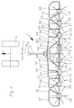
- die Draufsicht auf einen Kreiselheuwender mit 8 Zinkenkreiseln und den Schutzbügeln in der Arbeitsstellung,
- Fig. 2
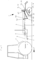
- eine Seitenansicht nach Fig. 1,
- Fig. 3
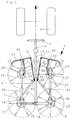
- die Draufsicht auf einen Kreiselheuwender mit geschwenkten Zinkenkreiseln und Schutzbügeln in der Transportstellung,
- Fig. 4
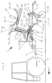
- eine Seitenansicht nach Fig. 3.
- Fig. 1
- the top view of a rotary tedder with 8 tine rotors and protective bars in the working position,
- Fig. 2
- 2 shows a side view according to FIG. 1,
- Fig. 3
- the top view of a rotary tedder with pivoted tine rotors and protective bars in the transport position,
- Fig. 4
- 3 shows a side view according to FIG. 3.
Ein in der Zeichnung dargestellter Kreiselheuwender (1) mit acht an Tragarmen angeordneten Zinkenkreiseln wird von einem Traktor (2) gezogen und angetrieben. An einem in Fahrtrichtung (F) verlaufenden starren Längsträger (3) ist an der Vorderseite eine Zugdeichsel (4) und ein Anschluß (5) für eine Gelenkwelle (6) zum Getriebe des Traktors (2) angeordnet. Die Zugdeichsel (4) ist mit der Zweipunktanhängung (7) des Traktors (2) verbunden. Am hinteren Ende des Längsträgers (3) ist ein Querträger (8) angeordnet. An den Querträger (8) schließen sich beidseitig mehrere um etwa vertikale Schwenkachsen (9, 10) nach vorn schwenkbare Tragarme mit daran angeordneten Zinkenkreiseln an. Am Querträger (8) sind zwei mittlere Zinkenkreisel (11, 12) und an den einzelnen Tragarmen ist jeweils ein Zinkenkreisel angeordnet. Der Antrieb der einzelnen Zinkenkreisel erfolgt vom Traktor (2) aus über die Gelenkwelle (6). Von dieser aus erfolgt die Weiterleitung der Drehbewegung über eine unterhalb des Längsträgers (3) angeordnete Antriebswelle (13) zum Eingangsgetriebe (14) am Querträger (8). An das Eingangsgetriebe (14) schließen sich beidseitig innerhalb des Querträgers (8) verlaufende Wellen an, die zu den Kreiselgetrieben (15, 16) der starr miteinander verbundenen mittleren Zinkenkreisel (11, 12) führen. Der Querträger (8) ist mit zwei höhenverstellbaren Transporträdern (17, 18) versehen, die unterhalb der Zinkenkreisel (11, 12) angebracht sind und die in der Arbeits- und Transportstellung ständig Bodenkontakt haben. Unterhalb der anderen Zinkenkreisel sind Tasträder (19) angeordnet. An den Querträger (8) schließen sich erste seitliche Tragarme (20, 21) an, an denen die ersten seitlichen Zinkenkreisel (22, 23) angeordnet sind. Die Tragarme (20, 21) sind um am Querträger (8) angebrachte horizontale Schwenkachsen (24, 25) nach oben und unten schwenkbar. Unterhalb der seitlichen Tragarme (20, 21) verlaufen Gelenkwellen, die die Drehbewegung von den Kreiselgetrieben (15, 16) der mittleren Zinkenkreisel (11, 12) zu den Kreiselgetrieben (26, 27) der ersten seitlichen Zinkenkreisel (22, 23) übertragen. An die ersten seitlichen Zinkenkreisel (22, 23) schließen sich die zweiten seitlichen Zinkenkreisel (28, 29) an, die an zweiten seitlichen Tragarmen (30, 31) befestigt und über horizontal angeordnete Schwenkachsen (32, 33) mit den Kreiselgetrieben (26, 27) der ersten seitlichen Zinkenkreisel (22, 23) antriebsmäßig verbunden sind. Die sich gelenkig daran anschließenden äußeren Zinkenkreisel (34, 35) sind an äußeren Tragarmen (36, 37) angebracht. Zwischen den ersten seitlichen Tragarmen (20, 21) und den äußeren Tragarmen (36, 37) sind Hydraulikzylinder (38) angeordnet, mit denen das Schwenken der äußeren Zinkenkreisel (34, 35) um die zugeordneten horizontalen Schwenkachsen (39, 40) und der zweiten seitlichen Zinkenkreisel (28, 29) um die Schwenkachsen (32, 33) erfolgt. Das Schwenken der seitlichen und äußeren Zinkenkreisel (22, 23, 28, 29, 34, 35) von der Arbeits- in die Transportstellung und umgekehrt erfolgt um die vertikalen Schwenkachsen (9, 10), die einen nach vorn gerichteten Neigungswinkel aufweisen. Zwischen dem Längsträger (3) und den ersten seitlichen Tragarmen (20, 21) sind einfachwirkende Hydraulikzylinder (41, 42) angeordnet. Durch sie werden die seitlichen und äußeren Zinkenkreisel (22, 23, 28, 29, 34, 35) von der Transportstellung in die Arbeitsstellung geschwenkt. Infolge der um etwa 15° nach vorn geneigten vertikalen Schwenkachsen (9, 10) schwenken die angehobenen seitlichen Zinkenkreisel (22, 23) nach dem Unterbrechen der Druckölzufuhr zu den Hydraulikzylindern (41, 42) selbstätig um etwa 90° nach vorn und gelangen dadurch in eine parallel zum Längsträger (3) verlaufende Transportstellung.A rotary tedder (1) shown in the drawing with eight tine rotors arranged on support arms is pulled and driven by a tractor (2). A drawbar (4) and a connection (5) for an articulated shaft (6) to the gearbox of the tractor (2) are arranged on the front of a rigid longitudinal beam (3) running in the direction of travel (F). The drawbar (4) is connected to the two-point hitch (7) of the tractor (2). A cross member (8) is arranged at the rear end of the longitudinal member (3). Connected to the crossmember (8) on both sides are a plurality of support arms which can be swiveled forward about approximately vertical swivel axes (9, 10) with tine rotors arranged thereon. Two central tine rotors (11, 12) are arranged on the crossmember (8) and one tine rotator is arranged on each of the support arms. The individual tine rotors are driven from the tractor (2) via the cardan shaft (6). From there, the rotary movement is forwarded via a drive shaft arranged below the longitudinal beam (3) (13) to the input gear (14) on the cross member (8). Shafts running on both sides within the crossmember (8) adjoin the input gear (14) and lead to the gyroscopic gears (15, 16) of the rigidly connected middle tine rotors (11, 12). The cross member (8) is provided with two height-adjustable transport wheels (17, 18) which are attached below the tine rotors (11, 12) and which are in constant contact with the ground in the working and transport position. Probe wheels (19) are arranged below the other tine rotors. First lateral support arms (20, 21) adjoin the cross member (8), on which the first lateral tine rotors (22, 23) are arranged. The support arms (20, 21) can be pivoted up and down about horizontal pivot axes (24, 25) attached to the cross member (8). Below the side support arms (20, 21) run cardan shafts which transmit the rotary movement from the gyroscopic gears (15, 16) of the middle tine rotors (11, 12) to the gyroscopic gears (26, 27) of the first lateral tine rotors (22, 23). The first lateral tine rotors (22, 23) are connected to the second lateral tine rotors (28, 29), which are attached to second lateral support arms (30, 31) and connected to the rotary drives (26, 33) via horizontally arranged swivel axes (32, 33). 27) of the first lateral tine rotors (22, 23) are connected in terms of drive. The outer tine rotors (34, 35) which are connected to it in an articulated manner are attached to outer support arms (36, 37). Between the first side support arms (20, 21) and the outer support arms (36, 37) hydraulic cylinders (38) are arranged, with which the pivoting of the outer tine rotors (34, 35) about the associated horizontal pivot axes (39, 40) and the second lateral tine gyro (28, 29) about the pivot axes (32, 33). The lateral and outer tine rotors (22, 23, 28, 29, 34, 35) are swiveled from the working to the transport position and vice versa about the vertical swivel axes (9, 10), which have a forward inclination angle. Single-acting hydraulic cylinders (41, 42) are arranged between the side member (3) and the first side support arms (20, 21). The side and outer tine rotors (22, 23, 28, 29, 34, 35) pivoted from the transport position into the working position. As a result of the vertical swivel axes (9, 10) inclined forward by approximately 15 °, the raised lateral tine rotors (22, 23) automatically swivel forward by approximately 90 ° after interrupting the pressure oil supply to the hydraulic cylinders (41, 42) and thereby get into a transport position running parallel to the side member (3).
Aus Arbeitsschutzgründen sind in der Arbeitsstellung vor den rotierenden Zinkenkreiseln über die gesamte Arbeitsbreite Schutzbügel angeordnet, die in der Transportstellung in eine platzsparende Lage gebracht werden, in der sie den Schwenkvorgang nicht behindern und mit dem Längsträger (3) des Maschinenrahmens und mit den benachbarten Schutzbügeln nicht kollidieren.For work safety reasons, protective bars are arranged in the working position in front of the rotating tine rotors over the entire working width, which are brought into a space-saving position in the transport position, in which they do not hinder the pivoting process and with the side member (3) of the machine frame and with the neighboring protective bars collide.
Zu diesem Zweck sind, in Fahrtrichtung (F) gesehen, vor den ersten seitlichen Zinkenkreiseln (22, 23) Schutzbügel (43, 44) angeordnet, die an Haltearmen (45, 46) starr befestigt sind. Die Haltearme (45, 46) sind über vertikal angeordnete Gelenkachsen (47, 48) mit den Gehäusen der Kreiselgetriebe (26, 27) der ersten seitlichen Zinkenkreisel (22, 23) schwenkbeweglich verbunden. An den dem Längsträger (3) zugewandten Ende der Schutzbügel (43, 44) sind Koppelstangen (49, 50) angebracht, deren andere Enden am Längsträger (3) angelenkt sind. Die Verbindung der Enden der Koppelstangen (49, 50) mit den Schutzbügeln (43, 44) bzw. mit dem Längsträger (3) erfolgt über kardanisch ausgebildete Gelenke (51, 52, 53, 54). Diese Gelenkausführung ermöglicht die Höhen-, Längs- und Schrägverschiebungen der jeweiligen Anlenkstellen, die beim Anheben und Schwenken der seitlichen und äusseren Zinkenkreisel (22, 23, 28, 29, 34, 35) nach oben und vorn auftreten. In der Arbeitsstellung übernehmen die Koppelstangen (49, 50) gleichzeitig die Funktion von Schutzbügeln für die mittleren Zinkenkreisel (11, 12). Beim Schwenkvorgang der Zinkenkreisel von der Arbeits- in die Transportstellung gelangen die Schutzbügel (43, 44) und die zugehörigen Koppelstangen (49, 50) selbstätig in eine solche bauraumsparende Lage oberhalb und vor die Zinkenkreisel (22, 23), in der keine Berührung mit dem Längsträger (3) erfolgt. Auf diese Weise können die seitlichen Zinkenkreisel (22, 23) bis nahe an den Längsträger (3) in eine etwa parallele Lage zu diesem geschwenkt werden, wodurch sich eine geringe Transportbreite des Kreiselheuwenders (1) ergibt.For this purpose, as seen in the direction of travel (F), protective brackets (43, 44) are arranged in front of the first lateral tine rotors (22, 23), which are rigidly attached to holding arms (45, 46). The holding arms (45, 46) are pivotally connected to the housings of the rotary drives (26, 27) of the first lateral tine rotors (22, 23) via vertically arranged articulated axes (47, 48). Coupling rods (49, 50) are attached to the end of the protective bracket (43, 44) facing the side member (3), the other ends of which are articulated on the side member (3). The ends of the coupling rods (49, 50) are connected to the protective brackets (43, 44) or to the side member (3) by means of gimbals (51, 52, 53, 54). This articulated design enables the vertical, longitudinal and inclined displacements of the respective articulation points that occur when lifting and swiveling the lateral and outer tine rotors (22, 23, 28, 29, 34, 35) upwards and forwards. In the working position, the coupling rods (49, 50) also act as protective bars for the middle tine rotors (11, 12). When the tine rotors are swiveled from the working to the transport position, the protective brackets move (43, 44) and the associated coupling rods (49, 50) automatically in such a space-saving position above and in front of the tine rotors (22, 23), in which there is no contact with the side member (3). In this way, the lateral tine rotors (22, 23) can be pivoted into an approximately parallel position to the longitudinal beam (3), resulting in a small transport width of the rotary tedder (1).
Eine weitere Möglichkeit zum Schwenken der Schutzbügel (43, 44) besteht darin, daß eine am Längsträger (3) angelenkte Steuerstange um eine horizontal angeordnete Schwenkachse nach oben geschwenkt wird. Die vertikale Schwenkachse der Schutzbügel (43, 44) muß in diesem Fall durch eine etwa horizontal verlaufende Schwenkachse ersetzt werden.Another possibility for pivoting the protective bracket (43, 44) is that a control rod articulated on the side member (3) is pivoted upward about a horizontally arranged pivot axis. In this case, the vertical swivel axis of the protective bracket (43, 44) must be replaced by an approximately horizontal swivel axis.
Den zweiten seitlichen Zinkenkreiseln (28, 29) sind fest mit diesen verbundene separate Schutzbügel (55, 56) zugeordnet. Um beim Schwenkvorgang der Zinkenkreisel (28, 29) eine gegenseitige Kollision der Schutzbügel (55, 56) zu vermeiden, sind diese höhenversetzt zueinander angeordnet.The second lateral tine rotors (28, 29) are assigned separate protective brackets (55, 56) that are firmly connected to them. In order to avoid a mutual collision of the protective brackets (55, 56) during the pivoting process of the tine rotors (28, 29), these are arranged offset in height from one another.
An den äußeren Zinkenkreiseln (34, 35) sind äußere Schutzbügel (57, 58) angebracht, die starr mit den Zinkenkreiseln (34, 35) verbunden und zur Vermeidung einer Kollisionsgefahr beim Schwenken der Zinkenkreisel (34, 35) in die Transportstellung ebenfalls höhenversetzt zueinander angeordnet sind.External protective brackets (57, 58) are attached to the outer tine rotors (34, 35), which are rigidly connected to the tine rotors (34, 35) and are also offset in height from each other to avoid a risk of collision when the tine rotors (34, 35) are pivoted into the transport position are arranged.
Die Vermeidung der gegenseitigen Berührung der seitlichen und äußeren Zinkenkreisel (28, 29, 34, 35) ist auch durch ein Hochschwenken beider Seiten um unterschiedliche Schwenkwinkel möglich.Avoiding mutual contact of the lateral and outer tine rotors (28, 29, 34, 35) is also possible by swiveling both sides up by different swivel angles.
Claims (7)
Applications Claiming Priority (2)
| Application Number | Priority Date | Filing Date | Title |
|---|---|---|---|
| DE19541654 | 1995-11-08 | ||
| DE19541654A DE19541654A1 (en) | 1995-11-08 | 1995-11-08 | Arrangement of protective bars for multi-rotor tedders |
Publications (2)
| Publication Number | Publication Date |
|---|---|
| EP0772968A1 true EP0772968A1 (en) | 1997-05-14 |
| EP0772968B1 EP0772968B1 (en) | 2002-01-09 |
Family
ID=7776941
Family Applications (1)
| Application Number | Title | Priority Date | Filing Date |
|---|---|---|---|
| EP96116565A Expired - Lifetime EP0772968B1 (en) | 1995-11-08 | 1996-10-16 | Safety bow for rotary tedder having several rotors |
Country Status (3)
| Country | Link |
|---|---|
| EP (1) | EP0772968B1 (en) |
| AT (1) | ATE211606T1 (en) |
| DE (2) | DE19541654A1 (en) |
Cited By (3)
| Publication number | Priority date | Publication date | Assignee | Title |
|---|---|---|---|---|
| EP1495666A1 (en) * | 2003-07-04 | 2005-01-12 | Maschinenfabrik Bernard Krone GmbH | Haymaking machine |
| FR2891437A1 (en) * | 2005-10-05 | 2007-04-06 | Kuhn Sa Sa | Haymaking machine, especially a tedder, has guards with supple and retractable sections in front of rotors |
| EP3187035A1 (en) | 2015-12-29 | 2017-07-05 | Kuhn SA (Societe Anonyme) | Haying machine with a splash guard |
Families Citing this family (3)
| Publication number | Priority date | Publication date | Assignee | Title |
|---|---|---|---|---|
| DE10330386B4 (en) * | 2003-07-04 | 2009-12-03 | Maschinenfabrik Bernard Krone Gmbh | Hay-making machine |
| DE10330381B4 (en) * | 2003-07-04 | 2010-01-28 | Maschinenfabrik Bernard Krone Gmbh | Hay-making machine |
| DE202008009955U1 (en) | 2008-07-24 | 2009-12-10 | Alois Pöttinger Maschinenfabrik Gmbh | Hay-making machine |
Citations (8)
| Publication number | Priority date | Publication date | Assignee | Title |
|---|---|---|---|---|
| EP0083460A1 (en) * | 1981-12-22 | 1983-07-13 | C. van der Lely N.V. | Agricultural implement |
| DE8712165U1 (en) * | 1987-09-08 | 1987-10-29 | Fella-Werke Gmbh, 8501 Feucht, De | |
| DE8807510U1 (en) * | 1988-06-09 | 1989-07-06 | Alois Poettinger Landmaschinen-Gesellschaft Mbh, 8900 Augsburg, De | |
| EP0391093A1 (en) * | 1989-04-07 | 1990-10-10 | Claas Saulgau Gmbh | Agricultural machine |
| EP0454602A1 (en) * | 1990-04-27 | 1991-10-30 | Kuhn S.A. | Haymaking machine having several rotors |
| DE4128501A1 (en) | 1991-08-28 | 1993-03-04 | Krone Bernhard Gmbh Maschf | HAY ADVERTISING MACHINE |
| EP0541516A2 (en) * | 1987-06-23 | 1993-05-12 | C. van der Lely N.V. | A hay-making machine |
| DE9409143U1 (en) * | 1993-06-04 | 1994-08-04 | Kuhn Sa | Haymaking machine |
Family Cites Families (3)
| Publication number | Priority date | Publication date | Assignee | Title |
|---|---|---|---|---|
| DE8625784U1 (en) * | 1986-09-26 | 1987-03-05 | Kloeckner-Humboldt-Deutz Ag Zweigniederlassung Fahr, 7702 Gottmadingen, De | |
| DE3709097A1 (en) * | 1987-03-20 | 1988-09-29 | Khd Agrartechnik | CYLINDER HAY ADVERTISING MACHINE |
| DE3816123A1 (en) * | 1988-05-11 | 1989-11-23 | Claas Saulgau Gmbh | PROTECTIVE DEVICE FOR ROTARY HEAVY-DUTY MACHINES WITH FOLD-UP WORK TOOLS |
-
1995
- 1995-11-08 DE DE19541654A patent/DE19541654A1/en not_active Withdrawn
-
1996
- 1996-10-16 EP EP96116565A patent/EP0772968B1/en not_active Expired - Lifetime
- 1996-10-16 DE DE59608554T patent/DE59608554D1/en not_active Expired - Lifetime
- 1996-10-16 AT AT96116565T patent/ATE211606T1/en not_active IP Right Cessation
Patent Citations (8)
| Publication number | Priority date | Publication date | Assignee | Title |
|---|---|---|---|---|
| EP0083460A1 (en) * | 1981-12-22 | 1983-07-13 | C. van der Lely N.V. | Agricultural implement |
| EP0541516A2 (en) * | 1987-06-23 | 1993-05-12 | C. van der Lely N.V. | A hay-making machine |
| DE8712165U1 (en) * | 1987-09-08 | 1987-10-29 | Fella-Werke Gmbh, 8501 Feucht, De | |
| DE8807510U1 (en) * | 1988-06-09 | 1989-07-06 | Alois Poettinger Landmaschinen-Gesellschaft Mbh, 8900 Augsburg, De | |
| EP0391093A1 (en) * | 1989-04-07 | 1990-10-10 | Claas Saulgau Gmbh | Agricultural machine |
| EP0454602A1 (en) * | 1990-04-27 | 1991-10-30 | Kuhn S.A. | Haymaking machine having several rotors |
| DE4128501A1 (en) | 1991-08-28 | 1993-03-04 | Krone Bernhard Gmbh Maschf | HAY ADVERTISING MACHINE |
| DE9409143U1 (en) * | 1993-06-04 | 1994-08-04 | Kuhn Sa | Haymaking machine |
Cited By (4)
| Publication number | Priority date | Publication date | Assignee | Title |
|---|---|---|---|---|
| EP1495666A1 (en) * | 2003-07-04 | 2005-01-12 | Maschinenfabrik Bernard Krone GmbH | Haymaking machine |
| FR2891437A1 (en) * | 2005-10-05 | 2007-04-06 | Kuhn Sa Sa | Haymaking machine, especially a tedder, has guards with supple and retractable sections in front of rotors |
| WO2007141399A1 (en) * | 2005-10-05 | 2007-12-13 | Kuhn S.A. | Haying machine comprising improved protection means |
| EP3187035A1 (en) | 2015-12-29 | 2017-07-05 | Kuhn SA (Societe Anonyme) | Haying machine with a splash guard |
Also Published As
| Publication number | Publication date |
|---|---|
| ATE211606T1 (en) | 2002-01-15 |
| EP0772968B1 (en) | 2002-01-09 |
| DE59608554D1 (en) | 2002-02-14 |
| DE19541654A1 (en) | 1997-05-15 |
Similar Documents
| Publication | Publication Date | Title |
|---|---|---|
| DE2351065C2 (en) | ||
| EP1252808B1 (en) | Mowing device | |
| DE8022517U1 (en) | Haymaking machine. | |
| DE2426209B2 (en) | AGRICULTURAL MACHINE | |
| EP0464387B1 (en) | Hay-making machine | |
| AT406629B (en) | AGRICULTURAL WORKING MACHINE, IN PARTICULAR HIGH-SPEED TURNERS | |
| DE3911296A1 (en) | AGRICULTURAL WORKING MACHINE | |
| DE2858680C2 (en) | ||
| DE4340384B4 (en) | Hay-making machine | |
| DE60112351T2 (en) | Hay-making machine | |
| DE3632767A1 (en) | CYLINDER HAY ADVERTISING MACHINE | |
| EP0772968B1 (en) | Safety bow for rotary tedder having several rotors | |
| DE3543264A1 (en) | Rotary tedder | |
| EP0289864B1 (en) | Hay making machine | |
| EP0512326B1 (en) | Use of a demountable flange connection on a drawbar and drawn harvesting machine | |
| DE2622649C2 (en) | Tractor-powered tillage machine | |
| EP0772962B1 (en) | Method and device for swinging the rake members of a haymaker | |
| EP0571794B1 (en) | Agricultural working machine, especially rotating hay tedder | |
| DE1782700B2 (en) | Rotary haymaker | |
| DE3107696C2 (en) | ||
| DE4128501A1 (en) | HAY ADVERTISING MACHINE | |
| EP0460288A1 (en) | Haymaking machine | |
| DE4113299C2 (en) | ||
| DE2559341B2 (en) | Machine for spreading fertilizer and seeds | |
| DE2617970A1 (en) | HAYMAKING MACHINE |
Legal Events
| Date | Code | Title | Description |
|---|---|---|---|
| PUAI | Public reference made under article 153(3) epc to a published international application that has entered the european phase |
Free format text: ORIGINAL CODE: 0009012 |
|
| AK | Designated contracting states |
Kind code of ref document: A1 Designated state(s): AT DE FR NL |
|
| 17P | Request for examination filed |
Effective date: 19971114 |
|
| 17Q | First examination report despatched |
Effective date: 19990728 |
|
| GRAG | Despatch of communication of intention to grant |
Free format text: ORIGINAL CODE: EPIDOS AGRA |
|
| GRAG | Despatch of communication of intention to grant |
Free format text: ORIGINAL CODE: EPIDOS AGRA |
|
| GRAH | Despatch of communication of intention to grant a patent |
Free format text: ORIGINAL CODE: EPIDOS IGRA |
|
| GRAH | Despatch of communication of intention to grant a patent |
Free format text: ORIGINAL CODE: EPIDOS IGRA |
|
| GRAA | (expected) grant |
Free format text: ORIGINAL CODE: 0009210 |
|
| AK | Designated contracting states |
Kind code of ref document: B1 Designated state(s): AT DE FR NL |
|
| REF | Corresponds to: |
Ref document number: 211606 Country of ref document: AT Date of ref document: 20020115 Kind code of ref document: T |
|
| REF | Corresponds to: |
Ref document number: 59608554 Country of ref document: DE Date of ref document: 20020214 |
|
| ET | Fr: translation filed | ||
| PGFP | Annual fee paid to national office [announced via postgrant information from national office to epo] |
Ref country code: NL Payment date: 20021031 Year of fee payment: 7 |
|
| PLBE | No opposition filed within time limit |
Free format text: ORIGINAL CODE: 0009261 |
|
| STAA | Information on the status of an ep patent application or granted ep patent |
Free format text: STATUS: NO OPPOSITION FILED WITHIN TIME LIMIT |
|
| 26N | No opposition filed | ||
| PGFP | Annual fee paid to national office [announced via postgrant information from national office to epo] |
Ref country code: AT Payment date: 20031021 Year of fee payment: 8 |
|
| PG25 | Lapsed in a contracting state [announced via postgrant information from national office to epo] |
Ref country code: NL Free format text: LAPSE BECAUSE OF NON-PAYMENT OF DUE FEES Effective date: 20040501 |
|
| NLV4 | Nl: lapsed or anulled due to non-payment of the annual fee |
Effective date: 20040501 |
|
| PG25 | Lapsed in a contracting state [announced via postgrant information from national office to epo] |
Ref country code: AT Free format text: LAPSE BECAUSE OF NON-PAYMENT OF DUE FEES Effective date: 20041016 |
|
| PGFP | Annual fee paid to national office [announced via postgrant information from national office to epo] |
Ref country code: DE Payment date: 20060912 Year of fee payment: 11 |
|
| PG25 | Lapsed in a contracting state [announced via postgrant information from national office to epo] |
Ref country code: DE Free format text: LAPSE BECAUSE OF THE APPLICANT RENOUNCES Effective date: 20071002 |
|
| REG | Reference to a national code |
Ref country code: FR Ref legal event code: ST Effective date: 20080630 |
|
| PGFP | Annual fee paid to national office [announced via postgrant information from national office to epo] |
Ref country code: FR Payment date: 20061016 Year of fee payment: 11 |
|
| PG25 | Lapsed in a contracting state [announced via postgrant information from national office to epo] |
Ref country code: FR Free format text: LAPSE BECAUSE OF NON-PAYMENT OF DUE FEES Effective date: 20071031 |