EP0772191A2 - Informationsaufzeichnungseinrichtung - Google Patents
Informationsaufzeichnungseinrichtung Download PDFInfo
- Publication number
- EP0772191A2 EP0772191A2 EP96307570A EP96307570A EP0772191A2 EP 0772191 A2 EP0772191 A2 EP 0772191A2 EP 96307570 A EP96307570 A EP 96307570A EP 96307570 A EP96307570 A EP 96307570A EP 0772191 A2 EP0772191 A2 EP 0772191A2
- Authority
- EP
- European Patent Office
- Prior art keywords
- spindle motor
- motor
- information recording
- head
- recording device
- Prior art date
- Legal status (The legal status is an assumption and is not a legal conclusion. Google has not performed a legal analysis and makes no representation as to the accuracy of the status listed.)
- Withdrawn
Links
- 230000001360 synchronised effect Effects 0.000 claims abstract description 7
- 230000008859 change Effects 0.000 claims abstract description 3
- 230000005284 excitation Effects 0.000 claims description 9
- 238000000034 method Methods 0.000 claims description 4
- 230000003247 decreasing effect Effects 0.000 description 5
- XEEYBQQBJWHFJM-UHFFFAOYSA-N Iron Chemical compound [Fe] XEEYBQQBJWHFJM-UHFFFAOYSA-N 0.000 description 4
- 230000007246 mechanism Effects 0.000 description 4
- 230000008901 benefit Effects 0.000 description 3
- 210000000078 claw Anatomy 0.000 description 3
- 239000006249 magnetic particle Substances 0.000 description 3
- 230000009467 reduction Effects 0.000 description 3
- 238000010276 construction Methods 0.000 description 2
- 238000010586 diagram Methods 0.000 description 2
- 230000000694 effects Effects 0.000 description 2
- 229910052742 iron Inorganic materials 0.000 description 2
- 239000011159 matrix material Substances 0.000 description 2
- 230000001668 ameliorated effect Effects 0.000 description 1
- 230000003321 amplification Effects 0.000 description 1
- 238000006243 chemical reaction Methods 0.000 description 1
- 238000001514 detection method Methods 0.000 description 1
- 230000006866 deterioration Effects 0.000 description 1
- 238000005516 engineering process Methods 0.000 description 1
- 238000010438 heat treatment Methods 0.000 description 1
- 238000003199 nucleic acid amplification method Methods 0.000 description 1
- 230000004044 response Effects 0.000 description 1
Images

Classifications
-
- G—PHYSICS
- G11—INFORMATION STORAGE
- G11B—INFORMATION STORAGE BASED ON RELATIVE MOVEMENT BETWEEN RECORD CARRIER AND TRANSDUCER
- G11B19/00—Driving, starting, stopping record carriers not specifically of filamentary or web form, or of supports therefor; Control thereof; Control of operating function ; Driving both disc and head
- G11B19/20—Driving; Starting; Stopping; Control thereof
-
- G—PHYSICS
- G11—INFORMATION STORAGE
- G11B—INFORMATION STORAGE BASED ON RELATIVE MOVEMENT BETWEEN RECORD CARRIER AND TRANSDUCER
- G11B19/00—Driving, starting, stopping record carriers not specifically of filamentary or web form, or of supports therefor; Control thereof; Control of operating function ; Driving both disc and head
Definitions
- the present invention relates to an information recording device such as for example an FDD, wherein the information is accessed by rotating a disk-shaped recording medium.
- An FDD floppy disk drive
- the spindle motor that is employed to effect rotary drive of the floppy disk in an FDD needs to have a wide torque range and high rotational accuracy is demanded, so, conventionally, a DC brushless motor was usually employed.
- a DC motor is available at low cost and can provide high torque but requires a brush and so suffers from problems regarding reliability and is therefore not used much.
- a DC brushless motor suffers from no problems at all with respect to reliability, but needs to be provided with a position detector and is therefore unavoidably expensive.
- a low-cost synchronous motor in particular a two-phase stepping motor
- the motor is driven under open-loop control obtained by low-cost digital processing; whereby the demerit (poor motor drive efficiency) of the characteristics of the synchronous motor described above is overcome and drive efficiency of the drive motor raised by employing in appropriate manner the information possessed by the memory device itself.
- the amount of load torque originating from the head is a quantity that is proportional to the position of the head on the track (i.e. the radius).
- the load torque that is required by the spindle motor for rotation of the recording medium can be uniquely deduced from the position of the head (track) on the recording medium.
- This deduced information is used, in the form of an electrical input, as a torque command value to match the necessary load torque of the two-phase stepping motor that is used as the spindle motor.
- the necessary torque is decreased, so the electrical input to the spindle motor is lowered. Conversely, if the head is seeking the outer circumference of the recording medium, the necessary torque is increased, so the electrical input is increased.
- a synchronous motor is used as spindle motor to drive the disk for information recording, the mechanical output value required for the spindle motor is found from the positions of the head on the recording disk before and after access, and electrical input to the spindle motor being adjusted in accordance with the mechanical output value that is thus found.
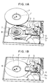
- FIG. 1A shows the condition with the recording disk removed and Fig. 1B shows the condition with the recording disk mounted.
- 1 is a disk-shaped recording medium (hereinbelow referred to as "recording disk”). Fine magnetic particles are coated in the form of concentric circles on both the upper and lower faces of this disk 1. A dish-shaped iron chucking hub 1' having two holes is inserted at the center of this disk 1. Recording disk 1 as a whole is received in a plastic case (not shown) to protect the faces of the recording medium and to facilitate transportation.
- head 2 is a head that is adapted read information recorded on the disk with a coil inside the head in contact with recording disk 1 in the form of magnetic changes of the magnetic particles.
- the information is written by applying magnetic changes to the magnetic particles on recording disk 1 by means of the coil in head 2.
- head 2 has the functions of both reading information that has been written onto recording disk 1 and of writing such information.
- Head 3 is a head carriage that carries head 2. Head 2 is arranged at its tip.
- Head carriage 3 is the mechanism whereby head 2 is moved linearly to a suitable position (track) on recording disk 1. It is constituted by a stepping motor 6 and a screw 5 that converts the rotary movement of this into linear movement. The conversion of rotary movement into linear movement is achieved by a part 3a of head carriage 3 engaging the groove of screw 5, so that, when screw 5 is rotated, the entire head carriage 3 is moved linearly. In this way, head 2 can be moved to any desired track position on recording disk 1 by means of a position command (determined by the number of pulses supplied to stepping motor 6) supplied to stepping motor 6.
- head 2 is in a contact-type arrangement, in which frictional force acts thereon due to contact of head 2 with recording disk 1. If in this case the speed of rotation of disk 1 is assumed to be constant and the coefficient of friction between disk 1 and head 2 is practically uniform over the disk surface, the necessary shaft output torque on spindle motor 7 due to the friction of the head 2 can be uniquely deduced as a quantity proportional to the radius on disk 1 (i.e. the track position). That is, the necessary shaft output torque of spindle motor 7 can be uniquely deduced from the position of head 2.
- a two-phase claw pole type stepping motor has the characteristic advantages of being of low cost and of enabling constant rotary drive to be produced by an open-loop control based on digital signal processing in a condition where no position detectors and no speed detector is provided. So, if such a motor is employed as a spindle motor, an extremely straightforward and low- cost construction can be achieved.
- a property of a two-phase stepping motor is that the speed of rotation and current are determined with respect to the load torque. So, in order to maintain these values constant irrespective of the amount of load, it is necessary to supply a large current even under low load conditions in order to guarantee stable rotation for a wide range of load torque. This results in a mode of use which is disadvantageous from the point of view of power saving. It is of course also disadvantageous from the point of view of vibration.
- an object of the present invention is to provide an information recording device whereby power saving and noise reduction can be achieved using an inexpensive two-phase stepping motor as a spindle motor.
- the means for achieving this is to control the electrical input to the spindle motor by deducing the necessary shaft output torque of the spindle motor from the head position (track) information. More specifically, if it is known that the head is moving towards the outside of the recording disk, the input power to the spindle motor is increased, thereby raising the generated shaft torque. If it is known that the head is moving towards the inside of the disk, the input power is decreased, thereby lowering the generated shaft output torque, thus saving power.
- the spindle motor in accordance recording device can be constituted wherein it is possible to employ a low cost motor as spindle motor and wherein power saving can be achieved.
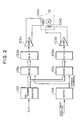
- Fig. 2 shows an embodiment of a motor control circuit of an information recording device according to the present invention.
- This embodiment is an example in which a two-phase claw pole type stepping motor is employed as the 3.5 inch FDD spindle motor, and this is rotated at a fixed speed of 300 rpm by a micro step drive. Details are shown below.
- 100 is an UP/DOWN counter that counts a clock pulse CLK and generates address signals of ROMs 101a and 101b.
- a plurality of excitation patterns of fixed frequency and different amplitude but of equal form factor are stored in ROM 101a and ROM 101b,; which pattern is selected is uniquely done by means of a torque command.
- D/A converters 102a, 102b convert the content of ROM 101a, 101b respectively to analogue voltages (generate excitation patterns). After power amplification by power amplifiers 103a, 103b, these are used to excite coils 104a, 104b of stepping motor 105.
- the information content recorded in ROMs 101a and 101b is of course such as to produce a so-called two-phase signal output, in which the phase relationship of D/A converters 102a, 102b represents a difference of 90° in terms of electrical angle.
- a sine wave is recorded on ROM 101a and a cosine wave is recorded on ROM 101b.
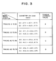
- Fig. 3 shows a specific example of the relationship of head track position to diameter on the recording disk to torque command in the motor control circuit of Fig. 2.
- the tracks of head track positions 0 to 79 are grouped into four zones consisting of tracks 0 to 19, tracks 20 to 39, tracks 40 to 59 and tracks 60 to 79, different torque commands being associated with these respective zones, as shown in A to D of Fig. 4.
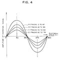
- Fig. 4 shows the excitation signals (sine waves) recorded in ROM 101a as a specific example of the four different torque command values A to D shown in Fig. 3.
- ROM 101a of Fig. 2 there are stored four sine waves of different amplitude and one or other of the four torque commands A to D is selected for output depending on the torque command to the spindle motor. It should be noted that, while it is desirable that the timing with which the torque command is altered should be simultaneous with the issuing of the torque command to the head actuator, it is an overriding precondition that the drive motor should not get out of synchronization, so it is necessary to alter this somewhat in the case where the head is going outwards towards the outer periphery or is moving inwards towards the inner perimeter.
- waveform of amplitude D is selected from ROM 101a and a voltage of smaller amplitude than hitherto is therefore supplied to spindle motor 105.
- the amount of torque generated by spindle motor 105 is decreased by an amount corresponding to that by which the input voltage to coils 104a, 104b of spindle motor 105 is decreased.
- the load torque is also decreased by that amount, there is no risk of out of synchronization etc. of spindle motor 105 due to insufficiency of torque.
- the input power to spindle motor 105 can be adjusted by uniquely calculating the necessary load torque from the head position; as a result, power-saving drive can be achieved.
- power-saving drive of spindle motor 105 can be achieved by altering the input power to spindle motor 105 in stepwise fashion (in four steps in the case of this embodiment), depending on head position.
- the input power to spindle motor 105 is changed over in four steps, there is of course no restriction to four steps and systems may of course be considered in which these steps are made smaller or, conversely, in which there is a rough changeover of for example two steps.
- Fig. 5 shows an embodiment in which the spindle motor current is adjusted.
- reference numbers that are the same as in Fig. 2 indicate identical structural elements.
- Excitation matrix 107a, 107b are logic matrix provided with the object of providing appropriate excitation timing and excitation current values to coils 104a, 104b of spindle motor 105, in accordance with the output of comparators 106a, 106b and the signal of UP/DOWN counter 100.
- the motor currents in coils 104a, 104b of spindle motor 105 can thus be made equal to the current commands issued by D/A converters 102a, 102b, and, if the amplitude of the current commands issued by ROMs 101a, 101b is selected in the same way as in the embodiment of Fig. 2 by having a plurality of excitation patterns of different current amplitudes stored in ROMs 101a and 101b and selecting the torque command issued to spindle motor 105 in accordance with the track position of the head, the input power can be adjusted by means of the input current to the spindle motor.
- the torque range of the spindle motor that is employed in the above embodiments can be chosen as a continuous region (pull-out region) of the stepping motor characteristic. If this is done, it is preferable to combine a frequency-varying circuit (ramp circuit) with the spindle motor drive.
Landscapes
- Rotational Drive Of Disk (AREA)
- Control Of Stepping Motors (AREA)
Applications Claiming Priority (2)
| Application Number | Priority Date | Filing Date | Title |
|---|---|---|---|
| JP283078/95 | 1995-10-31 | ||
| JP28307895A JP3387709B2 (ja) | 1995-10-31 | 1995-10-31 | 情報記録装置 |
Publications (2)
| Publication Number | Publication Date |
|---|---|
| EP0772191A2 true EP0772191A2 (de) | 1997-05-07 |
| EP0772191A3 EP0772191A3 (de) | 1997-07-16 |
Family
ID=17660932
Family Applications (1)
| Application Number | Title | Priority Date | Filing Date |
|---|---|---|---|
| EP96307570A Withdrawn EP0772191A3 (de) | 1995-10-31 | 1996-10-18 | Informationsaufzeichnungseinrichtung |
Country Status (3)
| Country | Link |
|---|---|
| US (1) | US5914581A (de) |
| EP (1) | EP0772191A3 (de) |
| JP (1) | JP3387709B2 (de) |
Cited By (1)
| Publication number | Priority date | Publication date | Assignee | Title |
|---|---|---|---|---|
| WO2004003913A1 (ja) * | 2002-06-28 | 2004-01-08 | Fujitsu Limited | 情報記憶装置 |
Families Citing this family (3)
| Publication number | Priority date | Publication date | Assignee | Title |
|---|---|---|---|---|
| JP3663302B2 (ja) * | 1998-08-20 | 2005-06-22 | 株式会社日立グローバルストレージテクノロジーズ | 磁気ディスク装置 |
| JP4553429B2 (ja) * | 1999-11-25 | 2010-09-29 | パナソニック株式会社 | ディスク装置 |
| US6717763B2 (en) * | 2001-05-16 | 2004-04-06 | Hitachi Global Storage Technologies, Netherlands B.V. | Power savings method and apparatus for disk drives |
Family Cites Families (9)
| Publication number | Priority date | Publication date | Assignee | Title |
|---|---|---|---|---|
| US4228387A (en) * | 1977-09-14 | 1980-10-14 | Exxon Research & Engineering Co. | Variable reluctance stepper motor drive and method of operation as a DC brushless motor |
| JPS59185071A (ja) * | 1983-04-04 | 1984-10-20 | Hitachi Ltd | 情報記録デイスクの再生速度制御装置 |
| JPH0724142B2 (ja) * | 1989-04-28 | 1995-03-15 | 株式会社ケンウッド | 光ディスクのサーボ回路 |
| DE4102796A1 (de) * | 1991-01-31 | 1992-08-06 | Thomson Brandt Gmbh | Verfahren zur verkuerzung der zugriffszeit |
| US5293565A (en) * | 1992-02-04 | 1994-03-08 | International Business Machines Corporation | Fortmat for data-storing disk media wherein addressable track angular length is independent of disk revolutions |
| US5225756A (en) * | 1992-03-26 | 1993-07-06 | David J. Coutu | Stepper motor driver circuit |
| DE4217557A1 (de) * | 1992-05-27 | 1993-12-02 | Bosch Gmbh Robert | Kontrollierte Mikroschrittsteuerung für einen Schrittmotor |
| US5576909A (en) * | 1995-02-16 | 1996-11-19 | Ministor Peripherals International Limited | Method for positioning a data transducer head in a rotating disk drive data storage device |
| US5691857A (en) * | 1995-09-29 | 1997-11-25 | Quantum Corporation | Method using matched filters for determining head positioner micro-jog in hard disk drive employing magneto-resistive heads |
-
1995
- 1995-10-31 JP JP28307895A patent/JP3387709B2/ja not_active Expired - Fee Related
-
1996
- 1996-10-16 US US08/732,036 patent/US5914581A/en not_active Expired - Fee Related
- 1996-10-18 EP EP96307570A patent/EP0772191A3/de not_active Withdrawn
Non-Patent Citations (1)
| Title |
|---|
| None |
Cited By (2)
| Publication number | Priority date | Publication date | Assignee | Title |
|---|---|---|---|---|
| WO2004003913A1 (ja) * | 2002-06-28 | 2004-01-08 | Fujitsu Limited | 情報記憶装置 |
| US7373529B2 (en) | 2002-06-28 | 2008-05-13 | Fujitsu Limited | Performing a power supply check for an information storage device to increase power consumption in a stepwise manner |
Also Published As
| Publication number | Publication date |
|---|---|
| JP3387709B2 (ja) | 2003-03-17 |
| EP0772191A3 (de) | 1997-07-16 |
| JPH09128885A (ja) | 1997-05-16 |
| US5914581A (en) | 1999-06-22 |
Similar Documents
| Publication | Publication Date | Title |
|---|---|---|
| US6754025B1 (en) | Disk drive spindle motor speed and timing control | |
| US4814909A (en) | Data transducer position control system for rotating disk data storage equipment | |
| US5835300A (en) | Dynamic compensation of servo burst measurement offsets in a disc drive | |
| JP2608223B2 (ja) | アクチュエータのトルク補正方法 | |
| US4739239A (en) | Bipolar motor control | |
| EP0776007B1 (de) | Informationsaufzeichnungsgerät | |
| US5914581A (en) | Information recording device | |
| JP2608220B2 (ja) | 磁気ディスク装置のポジション感度調整方法 | |
| US6065231A (en) | Motor drive method and drive circuit | |
| US6707269B2 (en) | Motor control circuit with adaptive dynamic range selection | |
| US11081988B1 (en) | Data storage device with spread spectrum spindle motor control | |
| US5731924A (en) | Track following method by using off-track and on-track offset adjusting method in magnetic disk driving device | |
| US6356519B1 (en) | Disk apparatus for moving head to center of target track in seek operation | |
| US20240062785A1 (en) | Dual spindle motors and dual spindle motor control for data storage | |
| US5880569A (en) | Motor for use in information recording device | |
| US4847704A (en) | Disk driving device | |
| JP3708522B2 (ja) | 磁気ディスク駆動装置 | |
| KR960005416B1 (ko) | 디스크드라이브 시스템 | |
| WO1998022940A1 (en) | Apparatus and method for servo system calibration of a removable diskette medium | |
| JPH06189515A (ja) | スピンドルモータ | |
| US20040150906A1 (en) | Servo writing method, servo writer, and program thereof | |
| JPWO2000043998A1 (ja) | ディスク装置 | |
| JPH03201274A (ja) | セクタサーボ復調制御方式 | |
| JPS61271675A (ja) | 磁気ヘツドの位置決めサ−ボ装置 | |
| JPS62298974A (ja) | ヘツド位置決め制御方法 |
Legal Events
| Date | Code | Title | Description |
|---|---|---|---|
| PUAI | Public reference made under article 153(3) epc to a published international application that has entered the european phase |
Free format text: ORIGINAL CODE: 0009012 |
|
| AK | Designated contracting states |
Kind code of ref document: A2 Designated state(s): DE GB |
|
| PUAL | Search report despatched |
Free format text: ORIGINAL CODE: 0009013 |
|
| AK | Designated contracting states |
Kind code of ref document: A3 Designated state(s): DE GB |
|
| STAA | Information on the status of an ep patent application or granted ep patent |
Free format text: STATUS: THE APPLICATION IS DEEMED TO BE WITHDRAWN |
|
| 18D | Application deemed to be withdrawn |
Effective date: 19980117 |