EP0772132A2 - Aktor/Sensor-Kombination für die Gebäudesystemtechnik - Google Patents
Aktor/Sensor-Kombination für die Gebäudesystemtechnik Download PDFInfo
- Publication number
- EP0772132A2 EP0772132A2 EP96113714A EP96113714A EP0772132A2 EP 0772132 A2 EP0772132 A2 EP 0772132A2 EP 96113714 A EP96113714 A EP 96113714A EP 96113714 A EP96113714 A EP 96113714A EP 0772132 A2 EP0772132 A2 EP 0772132A2
- Authority
- EP
- European Patent Office
- Prior art keywords
- actuator
- bus
- power
- flush
- socket
- Prior art date
- Legal status (The legal status is an assumption and is not a legal conclusion. Google has not performed a legal analysis and makes no representation as to the accuracy of the status listed.)
- Granted
Links
Images


Classifications
-
- H—ELECTRICITY
- H01—ELECTRIC ELEMENTS
- H01R—ELECTRICALLY-CONDUCTIVE CONNECTIONS; STRUCTURAL ASSOCIATIONS OF A PLURALITY OF MUTUALLY-INSULATED ELECTRICAL CONNECTING ELEMENTS; COUPLING DEVICES; CURRENT COLLECTORS
- H01R9/00—Structural associations of a plurality of mutually-insulated electrical connecting elements, e.g. terminal strips or terminal blocks; Terminals or binding posts mounted upon a base or in a case; Bases therefor
- H01R9/22—Bases, e.g. strip, block, panel
- H01R9/24—Terminal blocks
- H01R9/2458—Electrical interconnections between terminal blocks
-
- H—ELECTRICITY
- H02—GENERATION; CONVERSION OR DISTRIBUTION OF ELECTRIC POWER
- H02G—INSTALLATION OF ELECTRIC CABLES OR LINES, OR OF COMBINED OPTICAL AND ELECTRIC CABLES OR LINES
- H02G3/00—Installations of electric cables or lines or protective tubing therefor in or on buildings, equivalent structures or vehicles
- H02G3/02—Details
- H02G3/08—Distribution boxes; Connection or junction boxes
- H02G3/16—Distribution boxes; Connection or junction boxes structurally associated with support for line-connecting terminals within the box
Definitions
- the invention relates to an actuator / sensor combination for bus systems used in building system technology according to the preamble of claim 1.
- bus users In building system technology, devices, also called bus users, are connected via a bus line.
- the bus line consists of a two-wire line or network line, onto which bus signals are impressed.
- the bus participants are divided into sensors, actuators and other participants. Sensors are used to designate bus users that convert a physical variable into a bus telegram and send it to the bus.
- Actuators are bus participants who receive telegrams and convert them into actions.
- a function is implemented in the building system technology by the push button sensors and actuators, in that the push button sensor recognizes the actuation pressure of the operator, triggers a corresponding telegram, the telegram is sent via the bus, the actuator receives the telegram and converts it into a control action of its power section.
- bus participants consist of the Bus coupling unit, the application module and the application software.
- the telegram must be processed with the help of two bus couplers, namely a bus coupler in the sensor and a bus coupler in the actuator.
- the cost of two bus couplers is quite high and is hardly accepted by customers.
- Actuators today are mainly designed for installation in distribution or surface mounting. There are also actuators that can be used in a standard flush-mounted installation doo. Such actuators primarily consist of an application module as a power unit and a bus coupling unit.
- the bus coupling unit for flush-mounted installation fills out a flush-mounted box, so that its application module with the relay must be installed in a second flush-mounted box and thus forms the actuator.
- the power elements and bus couplers used individually in a separate flush-mounted box are routed from the power element to a socket on the bus coupler via a cable connection.
- the bus coupler socket is a widespread regulation of the EIBA (European Installation Bus Association). The plug connector of the bus coupling unit is thus occupied and cannot be used for other application modules such as sensors.
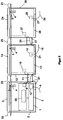
- Fig. 1 shows the basic structure of an actuator / sensor combination in flush-mounting boxes.
- the combination consists of two flush-mounted inserts, the actuator bus coupling unit 1 and the Power section 13.
- the actuator bus coupling unit 1 is inserted into a commercially available flush-mounted installation box 2 and connected to the bus line 6 via the connection point 10.
- the actuator bus coupler 1 contains a socket 4 into which the plugs 5 of a control unit 3 can be inserted.
- the actuator bus coupler 1 supplies the control unit 3 with voltage.
- the bus telegrams are taken over by a bus adapter 7 and processed further in a controller 8 with a microcontroller 38 in such a way that data are passed on to the control unit 3 and via a connection point 9 with the connecting line 11 to the power unit 13.
- the power unit 13 takes over the data from the connection point 18 into the controller 19 and controls the power unit 17 and the control unit 14 via the socket 4.
- the power unit 13 is connected via the connection point 16 to the line 15 to the 230 V network and the power supply 20 supplies the power element 17 and the control unit 14 with voltage. Operations on the control unit 3 are detected by the controller 8 via the socket 4.
- the controller 8 can now either transfer data to the power unit 13 and / or to the bus adapter 7, so that telegrams are sent on the bus, control processes are triggered in the power unit 17 and / or data are passed to the control unit 14. Operations on the control unit 14 are detected by the controller 19 via the socket 4.
- the controller 19 can now either control the power element 17 and / or transfer data to the actuator bus coupling unit 1, so that telegrams are sent to the bus 6 sent and / or data are given to the control unit 3.
- the power element 17 can be a relay, triac, transistor or another electromechanical or electronic component. This enables switching processes, dimming processes or blind controls to be set up, for example.
- the control units 3, 14 are commercially available application modules, as are used today for the flush-mounted bus coupling unit.
- the flush-mounted installation boxes 2 and 12 are commercially available installation boxes, through the openings 21 of which the connecting line 11, the bus line 6 and the power line 15 are guided.
- the actuator / sensor combination is mounted with a commercially available cover frame 22. No special installation boxes and cover frames are required.
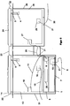
- FIG. 2 shows an actuator / sensor combination with a second power unit 28, the combination of FIG. 1 being expanded to include the second power unit 28. It is led via the connection point 27 with the connecting line 25 through the openings 21 of the flush-mounted installation boxes 2 and 12 to the connection point 9 of the actuator bus coupler 1.
- the power section 28 is in turn mounted in a commercially available flush-mounted installation box 26 and an operating section 24 is connected to the power section 28.
- the power line 30 is connected to the power section 28 through the opening 21 in the connection point 29.
- a commercially available cover frame 23 is used to install the actuator / sensor combination.
- the control unit 3 is supplied with voltage via the actuator bus coupling unit 1, while the control units 14 and 24 are supplied via the power units 13 and 28.
- 3 shows an embodiment of the actuator bus coupler 1 without sockets for the operating parts.
- the power section 13 and the actuator bus coupling unit 1 are mounted in a commercially available junction box 31 with openings 21.
- the bus adapter 7 and the controller 8 form the actuator bus coupler 1, which is connected in the connection point 10 to the bus line 6 through the opening 21 and in the connection point 9 to the connection lines 11, 25 and the connection to the power units 13 and 28 manufactures.
- Operating parts 14 and 24 can in turn be plugged onto the power units 13 and 28 and mounted with the cover frame 22.
- the power unit 28 is fastened in a flush-mounted installation box 26 and connected via the connection point 29 to the power line 30, which is guided through the opening 21 of the flush-mounted installation box 26.
- the power section 13 in the branch switch box 31 is connected to the power line 15 via the connection point 16.
- FIG. 4 shows the block diagram of a first and second power section 13, 28, which is connected via connection point 18, 27 via connection line 11, 25 to actuator bus coupling unit 1, via connection point 16, 29 to the mains voltage.
- the operating parts 14, 24 corresponding to FIGS. 1 to 3 are plugged onto the socket 4 of the power units 13, 28.
- the data exchange between the actuator bus coupling unit 1 and the power unit 13, 28 takes place by means of a microcontroller 39 via the adapter 32.
- the data exchange takes place with the respective control unit 14, 24 and a microcontroller 39 via the socket strip 4 and via an adapter 33.
- the Microcontroller 39 forwards the data via electrical isolation 34 to power element 35 in power element 13, 28, which controls a consumer (not shown).
- the voltage supply is achieved via a rectification unit 36 and a galvanic isolation 37.
- the power element 35 can be designed as a power transistor, triac, or relay and can be arranged once or several times.
Landscapes
- Engineering & Computer Science (AREA)
- Architecture (AREA)
- Civil Engineering (AREA)
- Structural Engineering (AREA)
- Details Of Connecting Devices For Male And Female Coupling (AREA)
- Burglar Alarm Systems (AREA)
- Air Bags (AREA)
- Arrangements For Transmission Of Measured Signals (AREA)
- Programmable Controllers (AREA)
Abstract
Description
- Die Erfindung betrifft eine Aktor/Sensor Kombination für Bussysteme der Gebäudesystemtechnik gemäß dem Oberbegriff des Anspruchs 1.
- In der Gebäudesystemtechnik sind Geräte, auch Busteilnehmer genannt, über eine Busleitung verbunden. Die Busleitung besteht aus einer Zweidrahtleitung oder Netzleitung, auf die Bussignale aufgeprägt werden. Die Busteilnehmer sind dabei in Sensoren, Aktoren und andere Teilnehmer unterteilt. Mit Sensoren werden Busteilnehmer bezeichnet, die eine physikalische Größe in ein Bustelegramm umwandeln und auf den Bus senden. Mit Aktoren werden Busteilnehmer bezeichnet, die Telegramme empfangen und in Aktionen umsetzen. Eine Funktion wird in der Gebäudesystemtechnik durch die Tastsensoren und Aktoren realisiert, indem der Tastsensor den Betätigungsdruck des Bedieners erkennt, ein entsprechendes Telegramm auslöst, das Telegramm über den Bus gesendet wird, der Aktor das Telegramm empfängt und es in eine Steuerhandlung seines Leistungsteils umsetzt. Der Aufbau von Busteilnehmern besteht aus dem Busankoppler, dem Anwendungsmodul und der Anwendungssoftware. Für die Funktion muß das Telegramm mit Hilfe von zwei Busankopplern verarbeitet werden, nämlich ein Busankoppler im Sensor und ein Busankoppler im Aktor. Die Kosten von zwei Busankopplern sind dabei recht hoch und werden von den Kunden kaum akzeptiert.
- Aktoren sind heute vornehmlich in den Bauformen für Verteilungseinbau oder für Aufputzmontage ausgeführt. Daneben gibt es auch Aktoren, die in eine handelsübliche Unterputzinstallationsdoes einsetzbar sind. Solche Aktoren bestehen vornehmlich aus einem Anwendungsmodul als Leistungsteil und einem Busankoppler. Der Busankoppler für Unterputzinstallation füllt eine Unterputzdose aus, so daß sein Anwendungsmodul mit dem Relais in eine zweite Unterputzdose montiert werden muß und damit den Aktor bildet. Die so jeweils einzeln in eine separate Unterputzdose eingesetzten Leistungsglieder und Busankoppler sind über eine Leitungsverbindung vom Leistungsglied auf eine Steckbuchse des Busankopplers geführt. Die Steckbuchse des Busankopplers ist eine weitverbreitete Vorschrift der EIBA (European Installation Bus Association). Damit ist die Steckbuchse des Busankopplers belegt und kann nicht für andere Anwendungsmodule wie Sensoren benutzt werden. Beide Unterputzdosen müssen verschlossen werden und erhalten deshalb eine Blindabdeckung; sie ist also nicht mehr bedienbar. Außerdem werden solche Blindabdeckungen in einem Gebäude als unästhetisch empfunden. Der zugehörige Stecker zur Steckbuchse des Busankopplers, der zum Leistungsglied führt, ragt mit seinen Leitungen über die Ebene der Unterputzdosen heraus, so daß zu deren Leitungsführung in die benachbarte Unterputzdose, die Abdeckrahmen mit Ausnehmungen versehen sein müssen. Zu der Installation dieser Geräte muß daher ein spezieller Abdeckrahmen bei den Herstellern, Großhändlern und Installateuren gelagert werden, was die Artikelanzahl erhöht.
- Der vorliegenden Erfindung liegt daher die Aufgabe zugrunde, busfähige Geräte der gattungsgemäßen Art so weiter zu entwickeln, daß sie gegenüber dem Stand der Technik folgende Forderungen erfüllen:
- 1.) Die busfähigen Geräte müssen vor Ort bedienbar sein.
- 2.) Sie müssen für aufsteckbare Bedienteile geeignet sein, die mit elektronischen Schaltungen und elektrisch ansteuerbaren Anzeigemitteln versehen sind.
- 3.) Die aufsteckbaren Bedienteile müssen galvanisch von der Netzleitung getrennt sein.
- 4.) Die busfähigen Installationsgeräte mit einem Leistungsteil oder mehreren Leistungsteilen müssen für unterschiedliche Gebrauchszwecke geeignet sein.
- 5.) Die busfähigen Installationsgeräte müssen mit handelsüblichen und gebräuchlichen Abdeckrahmen nutzbar sein.
- Diese Aufgabe wird durch die in Anspruch 1 gekennzeichneten Merkmale gelöst. Vorteilhafte Weiterbildungen sind in den Unteransprüchen angegeben. Anhand der Zeichnungsfiguren werden nachfolgend die Erfindung und dazu weitere vorteilhafte Ausgestaltungen näher erläutert. Es zeigt:
- Fig. 1
- den prinzipiellen Aufbau einer Sensor/Aktor-Kombination in Unterputzinstallationsdosen;
- Fig. 2
- eine Sensor/Aktor-Kombination gemäß Figur 1, jedoch erweitert um ein zweites Leistungsteil;
- Fig. 3
- eine Ausführungsform des Aktor-Busankopplers in einer Abzweig-Schalterdose;
- Fig. 4
- das Blockschaltbild eines Leistungsteiles.
- In den verschiedenen Zeichnungen sind gleiche Teile stets mit den gleichen Bezugszeichen versehen, so daß jede möglicherweise nur einmal unter Bezugnahme auf eine der Figuren vorkommende Beschreibung eines Teiles analog und auch bezüglich der anderen Zeichnungsfiguren gilt, in denen dies Teil mit entsprechenden Bezugszeichen ebenfalls zu erkennen ist. Fig. 1 zeigt den prinzipiellen Aufbau einer Aktor/Sensor-Kombination in Unterputzinstallationsdosen. Die Kombination besteht aus zwei Unterputzeinsätzen, dem Aktor-Busankoppler 1 und dem Leistungsteil 13. Der Aktor-Busankoppler 1 ist in eine handelsübliche Unterputzinstallationsdose 2 eingesetzt und über die Anschlußstelle 10 mit der Busleitung 6 verbunden. Der Aktor-Busankoppler 1 enthält eine Steckbuchse 4, in die die Stecker 5 eines Bedienteils 3 eingesteckt werden können. Der Aktor-Busankoppler 1 versorgt das Bedienteil 3 mit Spannung. Die Bustelegramme werden von einer Busanpassung 7 übernommen und in einer Steuerung 8 mit einem Mikrocontroller 38 in der Weise weiterverarbeitet, daß Daten an das Bedienteil 3 und über eine Anschlußstelle 9 mit der Verbindungsleitung 11 an das Leistungsteil 13 gegeben werden. Das Leistungsteil 13 übernimmt die Daten von der Anschlußstelle 18 in die Steuerung 19 und steuert das Leistungsglied 17 und das Bedienteil 14 über die Steckbuchse 4 an. Das Leistungsteil 13 ist über die Anschlußstelle 16 mit der Leitung 15 an das 230 V-Netz angeschlossen und die Spannungsversorgung 20 versorgt das Leistungsglied 17 und das Bedienteil 14 mit Spannung. Bedienungen an dem Bedienteil 3 werden von der Steuerung 8 über die Steckbuchse 4 erfaßt. Die Steuerung 8 kann nun entweder an das Leistungsteil 13 und/oder an die Busanpassung 7 Daten übergeben, so daß Telegramme auf den Bus gesendet, Steuervorgänge in dem Leistungsglied 17 ausgelöst und/oder Daten an das Bedienteil 14 gegeben werden. Bedienungen an dem Bedienteil 14 werden von der Steuerung 19 über die Steckbuchse 4 erfaßt. Die Steuerung 19 kann nun entweder das Leistungsglied 17 ansteuern und/oder Daten an den Aktor-Busankoppler 1 übergeben, so daß Telegramme auf den Bus 6 gesendet und/oder Daten an das Bedienteil 3 gegeben werden. Das Leistungsglied 17 kann ein Relais, Triac, Transistor oder ein anderes elektromechanisches oder elektronisches Bauteil sein. Damit können beispielsweise Schaltvorgänge, Dimmvorgänge oder Jalousiesteuerungen aufgebaut werden. Die Bedienteile 3, 14 sind handelsübliche Anwendungsmodule, wie sie heute für die Unterputz-Busankoppler benutzt werden. Die Unterputzinstallationsdosen 2 und 12 sind handelsübliche Installationsdosen, durch deren Öffnungen 21 die Verbindungsleitung 11, die Busleitung 6 und die Netzleitung 15 geführt wird. Die Aktor/Sensor Kombination wird mit einem handelsüblichen Abdeckrahmen 22 montiert. Es sind daher keine speziellen Installationsdosen und Abdeckrahmen erforderlich. Fig. 2 zeigt eine Aktor/Sensor Kombination mit einem zweiten Leistungsteil 28, wobei die Kombination der Fig. 1 um das zweite Leistungsteil 28 erweitert wurde. Es ist über die Anschlußstelle 27 mit der Verbindungsleitung 25 durch die Öffnungen 21 der Unterputzinstallationsdosen 2 und 12 zu der Anschlußstelle 9 des Aktor-Busankopplers 1 geführt. Das Leistungsteil 28 ist dabei wiederum in eine handelsübliche Unterputzinstallationsdose 26 montiert und ein Bedienteil 24 ist mit dem Leistungsteil 28 verbunden. Die Netzleitung 30 wird durch die Öffnung 21 in der Anschlußstelle 29 mit dem Leistungsteil 28 verbunden. Ein handelsüblicher Abdeckrahmen 23 dient der Installation der Aktor/Sensor Kombination.
- Bedienungen an den Bedienteilen 3, 14 und 24 werden von dem Aktor-Busankoppler 1 erfaßt und die entsprechenden Daten werden an das Bussystem 6 weitergegeben und/oder es werden Steuervorgänge in den Leistungsteilen 13 und 28 ausgelöst. Dabei erfolgt die Spannungsversorgung des Bedienteils 3 über den Aktor-Busankoppler 1, während die Bedienteile 14 und 24 über die Leistungsteile 13 und 28 versorgt werden. Fig. 3 zeigt eine Ausführungsform des Aktor-Busankopplers 1 ohne Buchsen für die Bedienteile. Das Leistungsteil 13 und der Aktor-Busankoppler 1 sind in eine handelsübliche Abzweig-Schalterdose 31 mit Öffnungen 21 montiert. Die Busanpassung 7 und die Steuerung 8 bilden dabei den Aktor-Busankoppler 1, der in der Anschlußstelle 10 mit der Busleitung 6 geführt durch die Öffnung 21 und in der Anschlußstelle 9 mit den Verbindungsleitungen 11, 25 verbunden ist und die Verbindung zu den Leistungsteilen 13 und 28 herstellt. Auf die Leistungsteile 13 und 28 können wiederum Bedienteile 14 und 24 aufgesteckt und mit dem Abdeckrahmen 22 montiert werden. Das Leistungsteil 28 ist in einer Unterputzinstallationsdose 26 befestigt und über die Anschlußstelle 29 mit der Netzleitung 30 verbunden, die durch die Öffnung 21 der Unterputzinstallationsdose 26 geführt ist. Das Leistungsteil 13 in der Abzweig-Schalterdose 31 ist über die Anschlußstelle 16 mit der Netzleitung 15 verbunden. Durch Bedienung an den Bedienteilen 14 und 24 oder durch Bustelegramme können unterschiedliche Abläufe in den Leistungsteilen 13 und/oder 28 oder in den Bedienteilen 14 und 24 ausgelöst werden.
- In Fig. 4 ist das Blockschaltbild eines ersten und zweiten Leistungsteils 13, 28 dargestellt, das über die Anschlußstelle 18, 27 über die Verbindungsleitung 11, 25 mit dem Aktor-Busankoppler 1, über die Anschlußstelle 16, 29 mit der Netzspannung, verbunden ist. Auf die Steckbuchse 4 der Leistungsteile 13, 28 werden die Bedienteile 14, 24 entsprechend der Fig. 1 bis 3 aufgesteckt. Der Datenaustausch zwischen dem Aktor-Busankoppler 1 und dem Leistungsteil 13, 28 erfolgt mittels eines Mikrocontrollers 39 über die Anpassung 32. Dabei erfolgt der Datenaustausch mit dem jeweiligen Bedienteil 14, 24 und einem Mikrocontroller 39 über die Buchsenleiste 4 und über eine Anpassung 33. Der Mikrocontroller 39 gibt die Daten über eine galvanische Trennung 34 an das Leistungsglied 35 im Leistungsteil 13, 28 weiter, das einen nicht dargestellten Verbraucher ansteuert. Die Spannungsversorgung wird über eine Gleichrichtungseinheit 36 und eine galvanische Trennung 37 der erreicht. Das Leistungsglied 35 kann dabei ausgebildet sein als Leistungstransistor, Triac, oder Relais und einmalig oder mehrmals angeordnet sein.
Claims (4)
- Aktor/Sensor Kombination für Bussysteme der Gebäudesystemtechnik, bestehend aus einem Busankoppler in einer ersten Unterputzinstallationsdose, der über eine Verbindungsleitung mit einem Leistungsteil in einer zweitem Unterputzinstallationsdose verbunden ist, wobei der Busankoppler mit einer Steckbuchse versehen ist und mit Mitteln zu deren Steuerung, Bedienung und Anzeige, gekennzeichnet durch die Kombination folgender Merkmale:1. daß der Aktor-Busankoppler (1) außer mit einer Steckbuchse (4) über eine Anschlußstelle (9) verfügt, womit eine Verbindungsleitung (11, 25) von einer ersten Unterputzinstallationsdose (2, 31) zu einer zweiten Unterputzinstallationsdose (12, 26) oder weiteren ermöglicht wird;2. wobei der Aktor-Busankoppler (1) und das Leistungsteil (13, 28) jeweils mit einer Steckbuchse (4) versehen ist, auf die ein Bedienteil (3, 14, 24) aufsteckbar ist;3. wobei als Steuerungsmittel ein Mikrocontroller (38) im Aktor-Busankoppler (1) vorgesehen ist, der mit einem oder mehreren Leistungsteilen (13, 28) den aufsteckbaren Bedienteilen (3, 14, 24) und mit einer Busanpassung (7) zusammenarbeitet;4. daß die Bedienteile (3, 14, 24) über EIBA standardisierte Stecker (5) verfügen;5. daß die Kombination von Aktor-Busankoppler (1), Leistungsteilen (13, 28) und Bedienteilen (3, 14, 24) mit handelsüblichen und gebräuchlichen Abdeckrahmen (22, 23) montierbar ist.
- Aktor/Sensor Kombination nach Anspruch 1, dadurch gekennzeichnet, daß die erste Unterputzinstallationsdose (2) als Abzweig-Schalterdose (31) ausgebildet ist, um ein Leistungsteil (13) und den Aktor Busankoppler (1) aufzunehmen, wobei der Aktor-Busankoppler (1) ohne die Steckbuchse (4) auskommt und die Verbindungsleitung (11) innerhalb der Abzweig-Schalterdose (31) angeordnet ist.
- Aktor/Sensor Kombination nach Anspruch 1 und 2 , dadurch gekennzeichnet daß die Bedienteile (14, 24) der Leistungsteile (13, 28) über eine galvanische Trennung (37) und eine Gleichrichtungseinheit (36) elektrisch versorgt werden. (Fig. 4)
- Aktor/Sensor Kombination nach Anspruch 1 bis 3, dadurch gekennzeichnet, daß ein Mikrokontroller (39) über eine galvanische Trennung (34) die Leistungsglieder (35) der Leistungsteile (13, 28) ansteuert.
Applications Claiming Priority (2)
| Application Number | Priority Date | Filing Date | Title |
|---|---|---|---|
| DE19541154A DE19541154A1 (de) | 1995-11-04 | 1995-11-04 | Aktor/Sensor Kombination für die Gebäudesystemtechnik |
| DE19541154 | 1995-11-04 |
Publications (3)
| Publication Number | Publication Date |
|---|---|
| EP0772132A2 true EP0772132A2 (de) | 1997-05-07 |
| EP0772132A3 EP0772132A3 (de) | 1998-04-29 |
| EP0772132B1 EP0772132B1 (de) | 2002-12-18 |
Family
ID=7776630
Family Applications (1)
| Application Number | Title | Priority Date | Filing Date |
|---|---|---|---|
| EP96113714A Expired - Lifetime EP0772132B1 (de) | 1995-11-04 | 1996-08-28 | Aktor/Sensor-Kombination für die Gebäudesystemtechnik |
Country Status (3)
| Country | Link |
|---|---|
| EP (1) | EP0772132B1 (de) |
| AT (1) | ATE230134T1 (de) |
| DE (2) | DE19541154A1 (de) |
Cited By (15)
| Publication number | Priority date | Publication date | Assignee | Title |
|---|---|---|---|---|
| EP0938179A3 (de) * | 1998-02-19 | 2000-05-31 | Siemens Aktiengesellschaft | Installationseinrichtung |
| WO2000037978A1 (de) * | 1998-12-22 | 2000-06-29 | Josef Faller | Kombination aus einem netzstecker und einem digitalen datenstecker |
| EP0855816A3 (de) * | 1997-01-23 | 2001-06-20 | INSTA ELEKTRO GmbH & Co. KG | Verfahren und Einrichtung zur Datenübertragung von einem Feldbus der Gebäudeleittechnik auf einen Busandkoppler für Anwendungsmodule der Gebäudesystemtechnik |
| EP0993094A3 (de) * | 1998-10-06 | 2003-08-06 | Insta Elektro GmbH | Elektrisches Installationssystem |
| EP1298845A3 (de) * | 2001-09-28 | 2004-06-30 | Siemens Aktiengesellschaft | Installationsgerät |
| EP1659434A1 (de) | 2004-11-16 | 2006-05-24 | Josef Faller | Anschlusseinheit |
| EP1677492A1 (de) * | 2001-12-11 | 2006-07-05 | GIRA Giersiepen GmbH & Co. KG | Modulare Hauskommunikationsanlage |
| EP1845602A1 (de) * | 2006-04-12 | 2007-10-17 | Servatec GmbH & Co. KG | Überwachungssystem |
| EP1748526A3 (de) * | 2005-07-28 | 2008-07-16 | Insta Elektro GmbH | Sensorkombination |
| DE102007017637A1 (de) | 2007-04-13 | 2008-10-16 | Hidde, Axel R., Dr. | Übertragungstechnik bei elektrischen Installationsgeräten |
| EP1993040A1 (de) * | 2007-05-12 | 2008-11-19 | Abb Ag | Sensoreinheit mit mehreren Bedien-oder Funktionselementen |
| EP1343240A3 (de) * | 2002-03-05 | 2010-05-26 | ABB PATENT GmbH | Bustechnik-Installationssystem |
| WO2011038973A3 (de) * | 2009-09-29 | 2012-01-26 | Siemens Aktiengesellschaft | Anordnung zum installieren von geräten der gebäudesystemtechnik |
| WO2011054542A3 (de) * | 2009-11-07 | 2012-03-29 | Luigi La Foresta | Vorrichtung zur aufnahme von elektrischen bauteilen |
| EP2924815A1 (de) | 2014-03-25 | 2015-09-30 | Berker GmbH & Co. KG | Montageschnittstelle für ein elektrisches Modul sowie entsprechende elektrische Vorrichtung |
Families Citing this family (9)
| Publication number | Priority date | Publication date | Assignee | Title |
|---|---|---|---|---|
| DE19944584A1 (de) * | 1999-09-17 | 2001-03-22 | Goetz Heuchemer | System zur Steuerung von räumlich verteilten elektrischen Verbrauchern in Gebäuden |
| DE20003432U1 (de) * | 2000-01-24 | 2001-06-13 | Rock, Horst, 90559 Burgthann | Unter Putz montierbares Klimagerät |
| DE10013303A1 (de) * | 2000-03-17 | 2001-09-20 | Abb Patent Gmbh | Ein-/Ausgabegerät zur Verwendung in einem Gebäudeinstallationssystem |
| DE10035813A1 (de) * | 2000-07-22 | 2002-01-31 | Abb Patent Gmbh | Installationsgerät für den Anschluß an Busleitungen eines Hausleitsystems, insbesondere des EIB-Bussystems |
| DE20201325U1 (de) | 2002-01-16 | 2003-05-28 | Rademacher Geräte-Elektronik GmbH & Co. KG, 46414 Rhede | Elektronisches Steuergerät |
| DE102004013344A1 (de) * | 2004-03-17 | 2005-10-27 | Insta Elektro Gmbh | Steuersystem |
| DE102004021679B4 (de) * | 2004-04-29 | 2007-10-11 | Josef Gerhard Geier | Elektroinstallationsanordnung |
| DE202009013405U1 (de) | 2009-10-22 | 2009-12-17 | Insta Elektro Gmbh | Für einen Einbau in eine Unterputzdose geeigneter Aktor für ein Gebäudeinstallationssystem |
| DE102010037200B4 (de) * | 2010-08-27 | 2012-06-28 | Insta Elektro Gmbh | Teilnehmer für ein Gebäudeinstallationssystem sowie Gebäudeinstallationssystem mit mehreren derartigen Teilnehmern |
Family Cites Families (10)
| Publication number | Priority date | Publication date | Assignee | Title |
|---|---|---|---|---|
| DE3426344A1 (de) * | 1984-07-17 | 1986-01-30 | Hans Ernst 4980 Bünde Cordes | Einsatz mit elektrischen schalter- bzw. steckkontakt-elementen fuer die installation in einer unterputzdose |
| DE3541475A1 (de) * | 1985-11-23 | 1987-07-23 | Kaiser Gmbh & Co Kg | Einbaudose, insbesondere unterputzdose fuer elektrische installationseinrichtungen |
| DE3800077A1 (de) * | 1988-01-05 | 1989-07-13 | Bosch Gmbh Robert | Dezentrale ein/ausgabebaugruppe fuer elektronische steuerungen |
| DE4013815C2 (de) * | 1990-04-30 | 1997-03-06 | Heesemann Juergen | Steuerschaltung für Maschinen |
| DE4200818A1 (de) * | 1992-01-15 | 1993-07-22 | Wieland Elektrische Industrie | Verteiler fuer elektrische installationssysteme |
| DE4216242C2 (de) * | 1992-05-16 | 1997-02-13 | Leuze Electronic Gmbh & Co | Identifizierung von Sensoren / Aktuatoren in Bussystemen |
| DE4225326C2 (de) * | 1992-07-31 | 1994-07-14 | Eberle Gmbh | Anschlußvorrichtung |
| DE9214324U1 (de) * | 1992-10-22 | 1992-12-17 | Siemens AG, 8000 München | Unterputzinstallationssystem |
| DE9302630U1 (de) * | 1993-02-24 | 1994-06-30 | Steuerungstechnik Staiger GmbH & Co. Produktions-Vertriebs-KG, 74391 Erligheim | Einrichtung für einen Aktor |
| DE4311096C2 (de) * | 1993-04-03 | 1996-06-20 | Abb Patent Gmbh | Teilnehmereinrichtung für ein Installationsbussystem |
-
1995
- 1995-11-04 DE DE19541154A patent/DE19541154A1/de not_active Withdrawn
-
1996
- 1996-08-28 AT AT96113714T patent/ATE230134T1/de not_active IP Right Cessation
- 1996-08-28 EP EP96113714A patent/EP0772132B1/de not_active Expired - Lifetime
- 1996-08-28 DE DE59609998T patent/DE59609998D1/de not_active Expired - Lifetime
Cited By (19)
| Publication number | Priority date | Publication date | Assignee | Title |
|---|---|---|---|---|
| EP0855816A3 (de) * | 1997-01-23 | 2001-06-20 | INSTA ELEKTRO GmbH & Co. KG | Verfahren und Einrichtung zur Datenübertragung von einem Feldbus der Gebäudeleittechnik auf einen Busandkoppler für Anwendungsmodule der Gebäudesystemtechnik |
| EP0938179A3 (de) * | 1998-02-19 | 2000-05-31 | Siemens Aktiengesellschaft | Installationseinrichtung |
| EP0993094A3 (de) * | 1998-10-06 | 2003-08-06 | Insta Elektro GmbH | Elektrisches Installationssystem |
| WO2000037978A1 (de) * | 1998-12-22 | 2000-06-29 | Josef Faller | Kombination aus einem netzstecker und einem digitalen datenstecker |
| EP1298845A3 (de) * | 2001-09-28 | 2004-06-30 | Siemens Aktiengesellschaft | Installationsgerät |
| EP1677492A1 (de) * | 2001-12-11 | 2006-07-05 | GIRA Giersiepen GmbH & Co. KG | Modulare Hauskommunikationsanlage |
| EP1343240A3 (de) * | 2002-03-05 | 2010-05-26 | ABB PATENT GmbH | Bustechnik-Installationssystem |
| EP1659434A1 (de) | 2004-11-16 | 2006-05-24 | Josef Faller | Anschlusseinheit |
| EP1748526A3 (de) * | 2005-07-28 | 2008-07-16 | Insta Elektro GmbH | Sensorkombination |
| EP1845602A1 (de) * | 2006-04-12 | 2007-10-17 | Servatec GmbH & Co. KG | Überwachungssystem |
| DE102007017637A1 (de) | 2007-04-13 | 2008-10-16 | Hidde, Axel R., Dr. | Übertragungstechnik bei elektrischen Installationsgeräten |
| EP1993040A1 (de) * | 2007-05-12 | 2008-11-19 | Abb Ag | Sensoreinheit mit mehreren Bedien-oder Funktionselementen |
| DE102007022342B4 (de) * | 2007-05-12 | 2009-07-09 | Abb Ag | Sensoreinheit mit mehreren Bedien- oder Funktionselementen |
| CN101303571B (zh) * | 2007-05-12 | 2012-11-07 | Abb股份有限公司 | 包括多个操作或功能元件的传感装置 |
| WO2011038973A3 (de) * | 2009-09-29 | 2012-01-26 | Siemens Aktiengesellschaft | Anordnung zum installieren von geräten der gebäudesystemtechnik |
| CN102549863A (zh) * | 2009-09-29 | 2012-07-04 | 西门子公司 | 用于安装建筑物系统技术设备的装置 |
| US20120182698A1 (en) * | 2009-09-29 | 2012-07-19 | Hans-Joachim Langels | Assembly for installing building systems engineering units |
| WO2011054542A3 (de) * | 2009-11-07 | 2012-03-29 | Luigi La Foresta | Vorrichtung zur aufnahme von elektrischen bauteilen |
| EP2924815A1 (de) | 2014-03-25 | 2015-09-30 | Berker GmbH & Co. KG | Montageschnittstelle für ein elektrisches Modul sowie entsprechende elektrische Vorrichtung |
Also Published As
| Publication number | Publication date |
|---|---|
| EP0772132A3 (de) | 1998-04-29 |
| EP0772132B1 (de) | 2002-12-18 |
| DE19541154A1 (de) | 1997-05-07 |
| ATE230134T1 (de) | 2003-01-15 |
| DE59609998D1 (de) | 2003-01-30 |
Similar Documents
| Publication | Publication Date | Title |
|---|---|---|
| EP0772132B1 (de) | Aktor/Sensor-Kombination für die Gebäudesystemtechnik | |
| EP0452658B1 (de) | Anschlusseinrichtung für die Hausleittechnik | |
| EP1064759B1 (de) | Verfahren zum inbetriebnehmen eines bussystems sowie entsprechendes bussystem | |
| DE4440102C1 (de) | Modulare Steuerungsanlage mit integriertem Feldbusanschluß | |
| AT504973B1 (de) | System und verfahren zur steuerung von busvernetzten geräten über einen offenen feldbus | |
| EP0436804B1 (de) | Elektrische Installationseinheit für die Hausleittechnik | |
| EP1258957B1 (de) | Schaltgerätesystem | |
| DE3236812A1 (de) | Fernwirksystem | |
| EP0790541A2 (de) | Anschlusseinrichtung für ein elektrisches Installationssystem | |
| EP0344609A2 (de) | Digitales Signalübertragungssystem für die Hausleittechnik | |
| DE102018129835A1 (de) | Steuerungssystem, Kopplermodul und Verfahren zur Montage eines Steuerungssystems | |
| EP0437696B1 (de) | Fernschalt- oder fernsteuerbare Anschlussvorrichtung | |
| EP2146401B2 (de) | Flexibler Mehrkanal-Kabelübergang | |
| DE19610381C2 (de) | Installationsbussystem für eine Stromschienenbeleuchtung | |
| DE29517477U1 (de) | Aktor/Sensor Kombination für die Gebäudesystemtechnik | |
| DE9405377U1 (de) | Datenschienenverbinder für den europäischen Installationsbus EIB | |
| EP1531524A1 (de) | Elektrischer Steckverbinder | |
| EP0855816B1 (de) | Busankoppler für Anwendungsmodule der Gebäudesystemtechnik | |
| DE19606579A1 (de) | Schalteranordnung zur An- und Abschaltung der elektrischen Energiezufuhr von elektrischen Verbrauchern | |
| DE19703160B4 (de) | Einrichtung zum Verbinden und Betreiben von Protokolliereinrichtungen in einer EIB-Anlage | |
| EP2650993A2 (de) | Anordnung zum Installieren von Geräten der Gebäudesystemtechnik | |
| EP0620525B1 (de) | EIB-Modul | |
| DE29701136U1 (de) | Busankoppler | |
| DE10204809A1 (de) | Gebäudeinstallationssystem | |
| AT500806B1 (de) | Bausatz von leiterplatten für den anschluss von elektrischen geräten, insbesondere dimmern, transformatoren und vorschaltgeräten |
Legal Events
| Date | Code | Title | Description |
|---|---|---|---|
| PUAI | Public reference made under article 153(3) epc to a published international application that has entered the european phase |
Free format text: ORIGINAL CODE: 0009012 |
|
| AK | Designated contracting states |
Kind code of ref document: A2 Designated state(s): AT BE CH DE DK FI FR LI NL SE |
|
| PUAL | Search report despatched |
Free format text: ORIGINAL CODE: 0009013 |
|
| AK | Designated contracting states |
Kind code of ref document: A3 Designated state(s): AT BE CH DE DK FI FR LI NL SE |
|
| 17P | Request for examination filed |
Effective date: 19980618 |
|
| 17Q | First examination report despatched |
Effective date: 20020122 |
|
| GRAH | Despatch of communication of intention to grant a patent |
Free format text: ORIGINAL CODE: EPIDOS IGRA |
|
| GRAH | Despatch of communication of intention to grant a patent |
Free format text: ORIGINAL CODE: EPIDOS IGRA |
|
| GRAA | (expected) grant |
Free format text: ORIGINAL CODE: 0009210 |
|
| AK | Designated contracting states |
Kind code of ref document: B1 Designated state(s): AT BE CH DE DK FI FR LI NL SE |
|
| PG25 | Lapsed in a contracting state [announced via postgrant information from national office to epo] |
Ref country code: NL Free format text: LAPSE BECAUSE OF FAILURE TO SUBMIT A TRANSLATION OF THE DESCRIPTION OR TO PAY THE FEE WITHIN THE PRESCRIBED TIME-LIMIT Effective date: 20021218 Ref country code: FR Free format text: LAPSE BECAUSE OF FAILURE TO SUBMIT A TRANSLATION OF THE DESCRIPTION OR TO PAY THE FEE WITHIN THE PRESCRIBED TIME-LIMIT Effective date: 20021218 Ref country code: FI Free format text: LAPSE BECAUSE OF FAILURE TO SUBMIT A TRANSLATION OF THE DESCRIPTION OR TO PAY THE FEE WITHIN THE PRESCRIBED TIME-LIMIT Effective date: 20021218 |
|
| REF | Corresponds to: |
Ref document number: 230134 Country of ref document: AT Date of ref document: 20030115 Kind code of ref document: T |
|
| REG | Reference to a national code |
Ref country code: CH Ref legal event code: EP |
|
| REF | Corresponds to: |
Ref document number: 59609998 Country of ref document: DE Date of ref document: 20030130 Kind code of ref document: P Ref document number: 59609998 Country of ref document: DE Date of ref document: 20030130 |
|
| PG25 | Lapsed in a contracting state [announced via postgrant information from national office to epo] |
Ref country code: SE Free format text: LAPSE BECAUSE OF FAILURE TO SUBMIT A TRANSLATION OF THE DESCRIPTION OR TO PAY THE FEE WITHIN THE PRESCRIBED TIME-LIMIT Effective date: 20030318 Ref country code: DK Free format text: LAPSE BECAUSE OF FAILURE TO SUBMIT A TRANSLATION OF THE DESCRIPTION OR TO PAY THE FEE WITHIN THE PRESCRIBED TIME-LIMIT Effective date: 20030318 |
|
| RAP2 | Party data changed (patent owner data changed or rights of a patent transferred) |
Owner name: INSTA ELEKTRO GMBH |
|
| PG25 | Lapsed in a contracting state [announced via postgrant information from national office to epo] |
Ref country code: AT Free format text: LAPSE BECAUSE OF NON-PAYMENT OF DUE FEES Effective date: 20030828 |
|
| PG25 | Lapsed in a contracting state [announced via postgrant information from national office to epo] |
Ref country code: LI Free format text: LAPSE BECAUSE OF NON-PAYMENT OF DUE FEES Effective date: 20030831 Ref country code: CH Free format text: LAPSE BECAUSE OF NON-PAYMENT OF DUE FEES Effective date: 20030831 Ref country code: BE Free format text: LAPSE BECAUSE OF NON-PAYMENT OF DUE FEES Effective date: 20030831 |
|
| PLBE | No opposition filed within time limit |
Free format text: ORIGINAL CODE: 0009261 |
|
| STAA | Information on the status of an ep patent application or granted ep patent |
Free format text: STATUS: NO OPPOSITION FILED WITHIN TIME LIMIT |
|
| EN | Fr: translation not filed | ||
| 26N | No opposition filed |
Effective date: 20030919 |
|
| BERE | Be: lapsed |
Owner name: *INSTA ELEKTRO G.M.B.H. Effective date: 20030831 |
|
| REG | Reference to a national code |
Ref country code: CH Ref legal event code: PL |
|
| PGFP | Annual fee paid to national office [announced via postgrant information from national office to epo] |
Ref country code: DE Payment date: 20100805 Year of fee payment: 15 |
|
| REG | Reference to a national code |
Ref country code: DE Ref legal event code: R119 Ref document number: 59609998 Country of ref document: DE Effective date: 20120301 |
|
| PG25 | Lapsed in a contracting state [announced via postgrant information from national office to epo] |
Ref country code: DE Free format text: LAPSE BECAUSE OF NON-PAYMENT OF DUE FEES Effective date: 20120301 |