EP0772021A2 - Kühltürme - Google Patents
Kühltürme Download PDFInfo
- Publication number
- EP0772021A2 EP0772021A2 EP96307805A EP96307805A EP0772021A2 EP 0772021 A2 EP0772021 A2 EP 0772021A2 EP 96307805 A EP96307805 A EP 96307805A EP 96307805 A EP96307805 A EP 96307805A EP 0772021 A2 EP0772021 A2 EP 0772021A2
- Authority
- EP
- European Patent Office
- Prior art keywords
- control valve
- flow control
- pressure
- pump
- hydraulic
- Prior art date
- Legal status (The legal status is an assumption and is not a legal conclusion. Google has not performed a legal analysis and makes no representation as to the accuracy of the status listed.)
- Withdrawn
Links
- 238000001816 cooling Methods 0.000 title claims abstract description 77
- 238000011144 upstream manufacturing Methods 0.000 claims abstract description 19
- 239000007788 liquid Substances 0.000 claims abstract description 16
- XLYOFNOQVPJJNP-UHFFFAOYSA-N water Substances O XLYOFNOQVPJJNP-UHFFFAOYSA-N 0.000 description 18
- 239000003570 air Substances 0.000 description 13
- 238000006073 displacement reaction Methods 0.000 description 13
- 230000001276 controlling effect Effects 0.000 description 8
- 230000007423 decrease Effects 0.000 description 7
- 230000003247 decreasing effect Effects 0.000 description 6
- 238000010586 diagram Methods 0.000 description 4
- 239000003638 chemical reducing agent Substances 0.000 description 3
- 239000008400 supply water Substances 0.000 description 3
- 239000012080 ambient air Substances 0.000 description 2
- 238000010276 construction Methods 0.000 description 2
- 238000007689 inspection Methods 0.000 description 2
- 238000012423 maintenance Methods 0.000 description 2
- 230000001105 regulatory effect Effects 0.000 description 2
- 239000012530 fluid Substances 0.000 description 1
- 238000007710 freezing Methods 0.000 description 1
- 230000008014 freezing Effects 0.000 description 1
- 238000004519 manufacturing process Methods 0.000 description 1
Images


Classifications
-
- F—MECHANICAL ENGINEERING; LIGHTING; HEATING; WEAPONS; BLASTING
- F28—HEAT EXCHANGE IN GENERAL
- F28F—DETAILS OF HEAT-EXCHANGE AND HEAT-TRANSFER APPARATUS, OF GENERAL APPLICATION
- F28F27/00—Control arrangements or safety devices specially adapted for heat-exchange or heat-transfer apparatus
- F28F27/003—Control arrangements or safety devices specially adapted for heat-exchange or heat-transfer apparatus specially adapted for cooling towers
-
- F—MECHANICAL ENGINEERING; LIGHTING; HEATING; WEAPONS; BLASTING
- F28—HEAT EXCHANGE IN GENERAL
- F28C—HEAT-EXCHANGE APPARATUS, NOT PROVIDED FOR IN ANOTHER SUBCLASS, IN WHICH THE HEAT-EXCHANGE MEDIA COME INTO DIRECT CONTACT WITHOUT CHEMICAL INTERACTION
- F28C1/00—Direct-contact trickle coolers, e.g. cooling towers
-
- Y—GENERAL TAGGING OF NEW TECHNOLOGICAL DEVELOPMENTS; GENERAL TAGGING OF CROSS-SECTIONAL TECHNOLOGIES SPANNING OVER SEVERAL SECTIONS OF THE IPC; TECHNICAL SUBJECTS COVERED BY FORMER USPC CROSS-REFERENCE ART COLLECTIONS [XRACs] AND DIGESTS
- Y02—TECHNOLOGIES OR APPLICATIONS FOR MITIGATION OR ADAPTATION AGAINST CLIMATE CHANGE
- Y02B—CLIMATE CHANGE MITIGATION TECHNOLOGIES RELATED TO BUILDINGS, e.g. HOUSING, HOUSE APPLIANCES OR RELATED END-USER APPLICATIONS
- Y02B30/00—Energy efficient heating, ventilation or air conditioning [HVAC]
- Y02B30/70—Efficient control or regulation technologies, e.g. for control of refrigerant flow, motor or heating
-
- Y—GENERAL TAGGING OF NEW TECHNOLOGICAL DEVELOPMENTS; GENERAL TAGGING OF CROSS-SECTIONAL TECHNOLOGIES SPANNING OVER SEVERAL SECTIONS OF THE IPC; TECHNICAL SUBJECTS COVERED BY FORMER USPC CROSS-REFERENCE ART COLLECTIONS [XRACs] AND DIGESTS
- Y10—TECHNICAL SUBJECTS COVERED BY FORMER USPC
- Y10S—TECHNICAL SUBJECTS COVERED BY FORMER USPC CROSS-REFERENCE ART COLLECTIONS [XRACs] AND DIGESTS
- Y10S261/00—Gas and liquid contact apparatus
- Y10S261/11—Cooling towers
Definitions
- the present invention relates generally to cooling towers and specifically to a system for controlling the hydraulic drive or motor of a hydraulically driven cooling fan in a cooling tower.
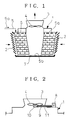
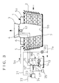
- FIGS 1 and 2 are diagrammatic side views of a known cooling tower for cooling warm water and of the drive for the cooling fan in the tower of Figure 1, respectively.
- Air suction passages defined by louver surfaces 2 are provided in the sides of the cooling tower main body 1.
- a cooling fan 4 for circulating air is installed in the air outlet 3 at the centre of the top of the main body 1. The fan 4 is driven to cause atmospheric air to flow through the air suction passages and the air passes through regulated passages in the main body 1 and is discharged through the outlet 3 to the atmosphere.
- a perforated warm-water receiver 6 is installed on the top of the main body 1 and receives warm water 5a from a supply line 5 constituting the medium to be cooled. The receiver 6 allows the warm water to flow down through the regulated passages.
- the warm water 5a which continuously flows down, comes into direct contact with the atmospheric air introduced through the air suction passages, and chilled water 5b is collected in a chilled water receptacle 7.
- an electric motor 8 is generally installed on the top of the main body 1, as shown in Figure 2, and a drive shaft 9 connected to the motor 8 extends into the main body 1 and transmits motive power to the cooling fan 4 via a speed reducer 10.
- a common mechanical support or bed supports the motor and the associated speed reducer, fan and shaft.
- the cooling fan 4 is of electrical motor-driven type and is generally driven with a blade tip speed of no more than 60 m/s.
- a single-speed motor is generally employed for driving the cooling fan, for the purpose of energy saving
- a pole change type (two-speed) motor may be used for operation at 50% or 100% of maximum speed; alternatively, a motor with an inverter may be utilized for operation at a variable speed of 50% to 100% of maximum speed.
- the cooling fan be driven by a hydraulic motor which in turn is operated by pressurised oil supplied by a hydraulic pump via a directional control valve.
- the hydraulic pump is driven by an electric motor and the directional control valve is controlled by electric signals.
- the construction of the prior document enables the hydraulic motor to be driven both in the normal and reverse directions and to be operated at a speed of 0 to 100% of maximum speed. It also enables the electric motor and the hydraulic pump to be installed at ground level, which facilitates maintenance and inspection. Further, only a relatively low starting current is taken since the electric motor is used only to drive the hydraulic pump.
- the output pressure of the hydraulic pump must be set to a value producing the maximum load torque which may be required during the year. Liquid discharged from the hydraulic pump is always at the above-mentioned maximum pressure, though its flow rate is automatically controlled to the required quantity of liquid passing through the directional control valve. Accordingly, when a lower load pressure at the hydraulic motor is acceptable or when a lower rotary speed of the cooling fan will suffice due to a reduced cooling requirement because of lower ambient air temperature in winter or the like, there is great difference between the pressure of the hydraulic pump for the maximum load torque condition and the lower load pressure actually required for the hydraulic motor which leads to pressure losses, resulting in energy losses.
- a cooling tower with a cooling fan driven by a hydraulic drive or motor with a control system which ensures that the hydraulic pressure provided by the hydraulic pump is never substantially greater than that required to rotate the fan at the speed which is necessary to satisfy the actual cooling requirement thereby resulting in an energy saving.
- a cooling tower for cooling a liquid including a cooling fan arranged to pass air through the cooling tower, a hydraulic motor connected to operate the fan, a pump, which is operated by a motor and is connected to the hydraulic motor via a hydraulic supply line which includes a flow control valve, a temperature detector for detecting the temperature of the liquid cooled within the cooling tower and a controller arranged to compare the detected temperature with a predetermined temperature and to control the flow control valve in dependence on the difference between the detected and predetermined temperatures is characterised in that the pump is of variable capacity type and that a capacity regulator is associated with the pump and arranged to vary the capacity of the pump to maintain a predetermined pressure differential between the pressures on the upstream and downstream sides of the flow control valve.
- the flow control valve in the supply line to the hydraulic motor is controlled in the usual manner, that is to say in dependence on the difference between the temperature of the cooled liquid and a predetermined reference temperature and the pressure drop across the flow control valve is controlled to be substantially at a predetermined value, such that the pressure on the upstream side is slightly higher than the pressure on the downstream side.
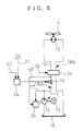
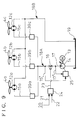
- the cooling fan 4 at the air outlet 3 at the top of the cooling tower main body 1 is connected to the output shaft of a hydraulic motor 12, and a variable capacity or variable displacement pump 14 driven by a motor 13 is installed on the ground surface.
- the supply side of the hydraulic motor 12 is connected to a flow control valve 16 (e.g. a known, proportional electromagnetic flow control valve) via a downstream side hydraulic pressure supply line 15, and the valve 16 is connected to the pump 14 via an upstream side hydraulic pressure supply line 17.
- the lines 15 and 17 together constitute a hydraulic pressure supply line 18A.
- the return side of the hydraulic motor 12 is connected to a tank 19 via a return line 18B so that the pressure liquid is returned to the suction side of the pump 14.
- a temperature detector 20 is provided for detecting the temperature of the chilled water 5b in the chilled water receptacle 7 or chilled water 5b to be supplied to a predetermined location via a water supply line 7a.
- a controller 24 is provided for comparing temperature 21 detected by the detector 20 with a preset or reference temperature 22 and controls the degree of opening of the flow control valve 16 by means of a control signal 23 generated in dependence on the difference between the above temperature values.
- the pump 14 is provided with a pressure-compensated variable capacity or variable displacement regulator 25 (pressure compensator).
- FIG. 4 shows an example of the regulator 25, which comprises capacity increasing biasing means 26, such as a spring, for biasing the capacity of the pump 14 in the increasing direction, an actuator 27 with a liquid chamber 27' for actuation in a direction to decrease the capacity of the pump 14 against the action of the biasing means 26 and a control valve 28 for controlling operation of the actuator 27.
- capacity increasing biasing means 26 such as a spring
- a low pressure port 30 connected via an orifice 29 to a branch line 15' of the downstream-side hydraulic pressure supply line 15 of the flow control valve 16 and a spring 31 for increasing the pressure of the port 30 as well as a port 28a for providing communication of the liquid chamber 27' of the actuator 27 with the tank 19.
- the spring 31 acts on the valve 28 and increases the force acting on the hydraulic fluid, thereby increasing the pressure at the port 30.
- the capacity decreasing side, B of the control valve 28 there are provided a high pressure port 32 connected via a branch line 17' to the upstream side hydraulic pressure supply line 17 of the flow control valve 16 and a port 28b for applying the pressure of the branch line 17' to the liquid chamber 27' of the actuator 27.
- the capacity of the pump 14 is controlled via the actuator 27 such that the upstream side pressure of the flow control valve 16 is maintained at a value somewhat higher than the downstream-side pressure thereof.
- the hydraulic pressure on the downstream side of the flow control valve 16 is applied through the low pressure port 30, and the spring 31 is also provided.
- the flow control valve 28 is pushed by a pressure somewhat higher than the hydraulic pressure of the downstream side hydraulic pressure supply line 15.
- this pushing force on the capacity increasing side A becomes equal to the pushing force on the capacity decreasing side B of the flow control valve 28 which is due to the hydraulic pressure on the upstream side of the flow control valve 16 applied through the high pressure port 32, (i.e. when the upstream side pressure is higher than the downstream side pressure by a preset pressure value set by the spring 31)
- the control valve 28 is balanced at an intermediate position where both the ports 28a and 28b are closed.
- force of the spring 31 is set or determined such that the difference between the hydraulic pressure on the upstream side of the flow control valve 16 and the hydraulic pressure on the downstream side is at an irreducible minimum value.
- a maximum pressure setting valve 33 Downstream of the orifice 29 in the branch line 15', a maximum pressure setting valve 33 is provided downstream of the orifice 29 in the branch line 15'.
- the maximum pressure setting valve 33 is opened to the tank 19.
- the capacity decreasing side B of the control valve 28 is then opened, and the hydraulic pressure on the upstream side hydraulic pressure supply line 17 is supplied to actuating side of the actuator 27, and the actuator is extended.
- the capacity of the variable displacement pump 14 is thus decreased against the action of the biasing means 26, thereby ensuring safety of the system.
- the temperature 21 of the chilled water 5b detected by the detector 20 in the supply water line 7a in Figure 3 is compared with the preset temperature 22 input into the controller 24, and the flow control valve 16 is controlled by the control signal 23. If the detected temperature 21 is higher than the preset temperature 22, the controller 24 opens the flow control valve 16 to increase the flow rate through the valve 16, whereby the speed of the cooling fan 4 driven by the hydraulic motor 12 is increased to enhance cooling of the warm water 5a. Thus, the temperature of the chilled water 5b is controlled to the preset temperature 22.
- the controller 24 acts to throttle the flow control valve 16 and reduces the flow rate in the valve 16. As a result, the speed of the cooling fan 5 driven by the hydraulic motor 12 is reduced. Thus, cooling of the warm water 5a is reduced and the temperature of the chilled water 5b is controlled up to the preset temperature 22. In this way, temperature of the supply water is always maintained at the preset temperature 22.
- the control valve 28 In the state in which the control valve 28 is kept in balance, when the flow control valve 16 is controlled to throttle flow through it, the pressure drop across the flow control valve 16 increases and the pressure on the downstream side is reduced. The pressure applied to the low pressure port 30 of the control valve 28 then decreases and the pressure at the low pressure port 30 is reduced more than the pressure of the high pressure port 32. Thus, the control valve 28 is controlled to open the port 28b, and the hydraulic pressure in the upstream side hydraulic pressure supply line 17 upstream of the flow control valve 16 is supplied to the liquid chamber 27' of the actuator 27, and the actuator 27 is extended. The action of the capacity increasing biasing means 26 is consequently overcome and the capacity of the variable displacement pump 14 is reduced. As a result, the pressure at the low pressure port 30 of the control valve 28 keeps in balance with the pressure at the high pressure port 32, and the system is brought to equilibrium.
- FIG. 5 shows an embodiment in which a normal-reverse switching valve 34 is provided across the downstream side hydraulic pressure supply line 15 connected to the hydraulic motor 12 and the return line 18B.
- the louver surfaces 2 may be frozen up when cold air is introduced.
- the normal-reverse switching valve 34 is switched over in the direction of arrow 35 manually or automatically to operate the cooling fan 4 in the reverse direction, warm air is blown out through the air suction passages thereby preventing freezing of the louver surfaces 2.
- Figure 6 shows an embodiment in which a normal-reverse switching flow control valve 40 (e.g. a known, proportional electromagnetic directional flow control valve), which serves as both the flow control valve 16 and the normal-reverse switching valve 34 of Figure 5 is provided across the supply line 18A and the return line 18B, and is controlled by commands from the controller 24.
- a normal-reverse switching flow control valve 40 e.g. a known, proportional electromagnetic directional flow control valve
- FIG. 6 shows an embodiment in which a normal-reverse switching flow control valve 40 (e.g. a known, proportional electromagnetic directional flow control valve), which serves as both the flow control valve 16 and the normal-reverse switching valve 34 of Figure 5 is provided across the supply line 18A and the return line 18B, and is controlled by commands from the controller 24.
- the purpose and operation of this embodiment are the same as those of Figure 5.
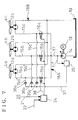
- FIG. 7 shows an embodiment in which a plurality of cooling fans, in this case three fans 4a, 4b and 4c, are provided which are driven by respective hydraulic motors 12a, 12b and 12c.
- flow control valves 16a, 16b and 16c are respectively arranged on the downstream side of the hydraulic pressure supply lines 15a, 15b and 15c, branching off from the upstream side of the hydraulic pressure supply line 17 supplied from a single variable displacement pump.
- Check valves 36a, 36b and 36c are respectively arranged in the outflow direction in the branch lines 15a', 15b' and 15c' connected to the downstream side of the flow control valves 16a, 16b and 16c.
- the outlets of the check valves 36a, 36b and 36c are connected to a pilot line 37 connected to the pressure-compensated variable displacement regulator 25; and the branch line 17' is connected to the regulator 25.
- the highest hydraulic pressure in the three downstream side hydraulic pressure supply lines 15a, 15b and 15c is introduced into the pressure-compensated variable displacement regulator 25 as the pilot pressure, and the discharge pressure of the variable displacement pump 14 is controlled to a pressure value somewhat higher than the driving pressure of the hydraulic motor 12, which is the highest loading pressure.
- stop signal 38 to stop the cooling fan 4a is produced only at a time when, when operation is switched over to the remaining two cooling fans 4b and 4c, the speed of each of the fans 4b and 4c will not exceed a maximum limit.
- the flow control valves 16a, 16b and 16c are provided in the downstream side hydraulic pressure supply lines 15a, 15b and 15c so that the speed of each of the cooling fans 4a, 4b and 4c can be independently controlled.
- cooling fans 4a, 4b and 4c are operated at almost the same speed to control the water temperature in the cooling tower as a whole.
- the properties of cooling fans are generally such that, when their number of revolutions per unit time, i.e. speed, increases in the normal operating range, the required driving torque also increases.
- the hydraulic supply pressure to the hydraulic motors 12a, 12b and 12c is theoretically in proportion to the driving torque of the cooling fans, and the liquid supply flow rate is in proportion to the speed of the cooling fans.
- Figure 9 shows an embodiment in which a hydraulic system is provided which is more economical than that of Figure 7 by utilizing this property of the cooling fans 4a, 4b and 4c.
- a single flow control valve 16 is arranged in the upstream side hydraulic pressure supply line 17, and the pressure-compensated variable displacement regulator 25 is connected to the downstream and upstream sides of the flow control valve 16 via branch lines 15' and 17'.
- the supply line 18A is branched to form downstream side hydraulic pressure supply lines 15a, 15b and 15c at a point downstream of the branching point of the branch line 15'.
- shut-off valves 39a, 39b and 39c such as electromagnetic valves, are installed in the downstream side hydraulic pressure supply lines 15a, 15b and 15c.
- one of the shut-off valves 39a, 39b or 39c can be operated to reduce the number of the hydraulic motors 12a, 12b and 12c in operation, whereby the remaining hydraulic motors and the associated cooling fans can be operated more efficiently.
Landscapes
- Engineering & Computer Science (AREA)
- Mechanical Engineering (AREA)
- General Engineering & Computer Science (AREA)
- Physics & Mathematics (AREA)
- Thermal Sciences (AREA)
- Fluid-Pressure Circuits (AREA)
- Structures Of Non-Positive Displacement Pumps (AREA)
- Motor Or Generator Cooling System (AREA)
Applications Claiming Priority (2)
| Application Number | Priority Date | Filing Date | Title |
|---|---|---|---|
| JP7281611A JP2701812B2 (ja) | 1995-10-30 | 1995-10-30 | 冷水塔の冷却ファン液圧駆動制御装置 |
| JP281611/95 | 1995-10-30 |
Publications (2)
| Publication Number | Publication Date |
|---|---|
| EP0772021A2 true EP0772021A2 (de) | 1997-05-07 |
| EP0772021A3 EP0772021A3 (de) | 1998-08-05 |
Family
ID=17641555
Family Applications (1)
| Application Number | Title | Priority Date | Filing Date |
|---|---|---|---|
| EP96307805A Withdrawn EP0772021A3 (de) | 1995-10-30 | 1996-10-29 | Kühltürme |
Country Status (4)
| Country | Link |
|---|---|
| US (1) | US5851441A (de) |
| EP (1) | EP0772021A3 (de) |
| JP (1) | JP2701812B2 (de) |
| KR (1) | KR100218205B1 (de) |
Cited By (6)
| Publication number | Priority date | Publication date | Assignee | Title |
|---|---|---|---|---|
| CN101865613A (zh) * | 2010-06-09 | 2010-10-20 | 中国科学院电工研究所 | 基于动力合成器的冷却塔综合节能系统及其控制方法 |
| CN102589343A (zh) * | 2012-03-06 | 2012-07-18 | 德州贝诺风力机械设备有限公司 | 冷却塔水电混合动力装置 |
| CN102817764A (zh) * | 2012-08-01 | 2012-12-12 | 上海交通大学 | 循环冷却水系统富余扬程优化利用的技术装置 |
| CN103453783A (zh) * | 2013-08-19 | 2013-12-18 | 河海大学 | 一种储能动力源驱动与运行的冷却塔 |
| CN112484524A (zh) * | 2020-11-18 | 2021-03-12 | 暨南大学 | 立体式多级冷却湿式冷却塔及冷却方法 |
| CN114413361A (zh) * | 2022-01-20 | 2022-04-29 | 平顶山天安煤业股份有限公司 | 用于冷却塔的供水机构、冷却塔、空调系统和控制方法 |
Families Citing this family (7)
| Publication number | Priority date | Publication date | Assignee | Title |
|---|---|---|---|---|
| JP4204137B2 (ja) * | 1999-04-22 | 2009-01-07 | 株式会社小松製作所 | 冷却用ファンの駆動制御装置 |
| US6912859B2 (en) * | 2002-02-12 | 2005-07-05 | Air Liquide Process And Construction, Inc. | Method and apparatus for using a main air compressor to supplement a chill water system |
| US7073782B2 (en) * | 2004-01-09 | 2006-07-11 | Jcs/Thg, Llc | Humidifier |
| AU2010229238B2 (en) * | 2009-03-26 | 2014-06-26 | Crown Equipment Corporation | Working vehicle having cooling system |
| DE102010031835A1 (de) * | 2010-07-22 | 2012-01-26 | Liebherr-Werk Nenzing Gmbh | Lüfterregelung |
| CN112747626A (zh) * | 2020-12-31 | 2021-05-04 | 广州市昊铭机电科技有限公司 | 一种变参量冷却塔组节能自动控制系统及控制方法 |
| CN112833611A (zh) * | 2021-01-22 | 2021-05-25 | 深圳市奥宇节能技术股份有限公司 | 一种冷却循环水系统及其控制方法 |
Citations (1)
| Publication number | Priority date | Publication date | Assignee | Title |
|---|---|---|---|---|
| JPS5930046A (ja) | 1982-08-13 | 1984-02-17 | Takashima Sangyo Kk | 総ビリルビン値定量計 |
Family Cites Families (11)
| Publication number | Priority date | Publication date | Assignee | Title |
|---|---|---|---|---|
| US3130557A (en) * | 1962-05-23 | 1964-04-28 | Mcfarlan Alden Irving | Cooling tower control means |
| US4446697A (en) * | 1978-05-18 | 1984-05-08 | Eaton Corporation | Hydraulic fan drive system including variable displacement pump |
| CA1133609A (en) * | 1979-01-19 | 1982-10-12 | Naomichi Shito | Fan control system for cooling apparatus |
| US4459807A (en) * | 1982-02-05 | 1984-07-17 | Koppen And Lethem Ag | Control apparatus for fluid operated systems |
| US4474027A (en) * | 1983-01-31 | 1984-10-02 | The Babcock & Wilcox Company | Optimum control of cooling tower water temperature by function blocks |
| JPS60174500A (ja) * | 1984-02-20 | 1985-09-07 | Ishikawajima Harima Heavy Ind Co Ltd | 冷水塔の冷却フアン駆動装置 |
| KR920010875B1 (ko) * | 1988-06-29 | 1992-12-19 | 히다찌 겐끼 가부시기가이샤 | 유압구동장치 |
| US4955585A (en) * | 1989-06-22 | 1990-09-11 | Dickerson John A | Hydraulically driven fan system for water cooling tower |
| US5040377A (en) * | 1989-11-21 | 1991-08-20 | Johnson Service Company | Cooling system with improved fan control and method |
| JPH0518365A (ja) * | 1991-07-05 | 1993-01-26 | Komatsu Ltd | 可変容量型油圧ポンプの容量制御装置 |
| JPH0754803A (ja) * | 1993-08-12 | 1995-02-28 | Komatsu Ltd | 可変容量型油圧ポンプの容量制御装置 |
-
1995
- 1995-10-30 JP JP7281611A patent/JP2701812B2/ja not_active Expired - Fee Related
-
1996
- 1996-10-09 US US08/729,029 patent/US5851441A/en not_active Expired - Lifetime
- 1996-10-22 KR KR1019960047327A patent/KR100218205B1/ko not_active Expired - Fee Related
- 1996-10-29 EP EP96307805A patent/EP0772021A3/de not_active Withdrawn
Patent Citations (1)
| Publication number | Priority date | Publication date | Assignee | Title |
|---|---|---|---|---|
| JPS5930046A (ja) | 1982-08-13 | 1984-02-17 | Takashima Sangyo Kk | 総ビリルビン値定量計 |
Cited By (11)
| Publication number | Priority date | Publication date | Assignee | Title |
|---|---|---|---|---|
| CN101865613A (zh) * | 2010-06-09 | 2010-10-20 | 中国科学院电工研究所 | 基于动力合成器的冷却塔综合节能系统及其控制方法 |
| CN101865613B (zh) * | 2010-06-09 | 2012-09-26 | 中国科学院电工研究所 | 基于动力合成器的冷却塔综合节能系统及其控制方法 |
| CN102589343A (zh) * | 2012-03-06 | 2012-07-18 | 德州贝诺风力机械设备有限公司 | 冷却塔水电混合动力装置 |
| CN102817764A (zh) * | 2012-08-01 | 2012-12-12 | 上海交通大学 | 循环冷却水系统富余扬程优化利用的技术装置 |
| CN102817764B (zh) * | 2012-08-01 | 2014-11-12 | 上海交通大学 | 循环冷却水系统富余扬程优化利用的技术装置 |
| CN103453783A (zh) * | 2013-08-19 | 2013-12-18 | 河海大学 | 一种储能动力源驱动与运行的冷却塔 |
| CN103453783B (zh) * | 2013-08-19 | 2015-11-25 | 河海大学 | 一种储能动力源驱动与运行的冷却塔 |
| CN112484524A (zh) * | 2020-11-18 | 2021-03-12 | 暨南大学 | 立体式多级冷却湿式冷却塔及冷却方法 |
| CN112484524B (zh) * | 2020-11-18 | 2021-09-14 | 暨南大学 | 立体式多级冷却湿式冷却塔及冷却方法 |
| CN114413361A (zh) * | 2022-01-20 | 2022-04-29 | 平顶山天安煤业股份有限公司 | 用于冷却塔的供水机构、冷却塔、空调系统和控制方法 |
| CN114413361B (zh) * | 2022-01-20 | 2023-07-18 | 平顶山天安煤业股份有限公司 | 用于冷却塔的供水机构、冷却塔、空调系统和控制方法 |
Also Published As
| Publication number | Publication date |
|---|---|
| JP2701812B2 (ja) | 1998-01-21 |
| KR100218205B1 (ko) | 1999-09-01 |
| EP0772021A3 (de) | 1998-08-05 |
| JPH09126686A (ja) | 1997-05-16 |
| KR970022195A (ko) | 1997-05-28 |
| US5851441A (en) | 1998-12-22 |
Similar Documents
| Publication | Publication Date | Title |
|---|---|---|
| EP0772021A2 (de) | Kühltürme | |
| US5522707A (en) | Variable frequency drive system for fluid delivery system | |
| US4024710A (en) | Load sensing hydraulic circuit having power matching means | |
| US4330238A (en) | Automatic actuator for variable speed pump | |
| JPH0158357B2 (de) | ||
| US5284202A (en) | Compressor aftercooler apparatus for use in low temperature operations, and method of use | |
| EP0584110B1 (de) | Verfahren und anordnung zur kontrolle der luftzufuhr zu festgesteinsbohrmaschinen | |
| JP3868054B2 (ja) | 液圧的な駆動機構 | |
| CN102859185A (zh) | 转子叶片调节装置 | |
| US5201803A (en) | Hydraulic system for a vehicle | |
| US4487255A (en) | Control for a fluid-driven fan | |
| USH1977H1 (en) | Closed loop hydraulic system with variable charge pressure | |
| US7165397B2 (en) | Anti-stall pilot pressure control system for open center systems | |
| US4089346A (en) | Load responsive fluid control valves | |
| JP4410669B2 (ja) | 冷却ファン回路 | |
| US20140086759A1 (en) | Hydraulic Power System for HVAC Compressor | |
| JPS6256427B2 (de) | ||
| US3493167A (en) | Compressor control | |
| US4989495A (en) | Hydraulic positioning system with normal and high supply and exhaust flow paths | |
| US5241821A (en) | Hydraulic system for a vehicle | |
| JP4122640B2 (ja) | 冷水塔の冷却ファン液圧駆動装置 | |
| JPH06159741A (ja) | 地域冷暖房の熱媒搬送制御方法および熱媒搬送装置 | |
| JPH09317465A (ja) | 冷却用ファンの油圧駆動装置 | |
| US4716740A (en) | Controller apparatus and method for heat exchange system | |
| JPS58174707A (ja) | 複数機器油圧駆動回路 |
Legal Events
| Date | Code | Title | Description |
|---|---|---|---|
| PUAI | Public reference made under article 153(3) epc to a published international application that has entered the european phase |
Free format text: ORIGINAL CODE: 0009012 |
|
| AK | Designated contracting states |
Kind code of ref document: A2 Designated state(s): BE DE GB IT |
|
| PUAL | Search report despatched |
Free format text: ORIGINAL CODE: 0009013 |
|
| AK | Designated contracting states |
Kind code of ref document: A3 Designated state(s): BE DE GB IT |
|
| 17P | Request for examination filed |
Effective date: 19981109 |
|
| 17Q | First examination report despatched |
Effective date: 20001208 |
|
| STAA | Information on the status of an ep patent application or granted ep patent |
Free format text: STATUS: THE APPLICATION IS DEEMED TO BE WITHDRAWN |
|
| 18D | Application deemed to be withdrawn |
Effective date: 20020108 |