EP0771882A1 - Heat resistance stainless steel wire or strip - Google Patents
Heat resistance stainless steel wire or strip Download PDFInfo
- Publication number
- EP0771882A1 EP0771882A1 EP96307965A EP96307965A EP0771882A1 EP 0771882 A1 EP0771882 A1 EP 0771882A1 EP 96307965 A EP96307965 A EP 96307965A EP 96307965 A EP96307965 A EP 96307965A EP 0771882 A1 EP0771882 A1 EP 0771882A1
- Authority
- EP
- European Patent Office
- Prior art keywords
- stainless steel
- steel wire
- strip
- heat resistant
- aluminum
- Prior art date
- Legal status (The legal status is an assumption and is not a legal conclusion. Google has not performed a legal analysis and makes no representation as to the accuracy of the status listed.)
- Granted
Links
Images


Classifications
-
- C—CHEMISTRY; METALLURGY
- C23—COATING METALLIC MATERIAL; COATING MATERIAL WITH METALLIC MATERIAL; CHEMICAL SURFACE TREATMENT; DIFFUSION TREATMENT OF METALLIC MATERIAL; COATING BY VACUUM EVAPORATION, BY SPUTTERING, BY ION IMPLANTATION OR BY CHEMICAL VAPOUR DEPOSITION, IN GENERAL; INHIBITING CORROSION OF METALLIC MATERIAL OR INCRUSTATION IN GENERAL
- C23C—COATING METALLIC MATERIAL; COATING MATERIAL WITH METALLIC MATERIAL; SURFACE TREATMENT OF METALLIC MATERIAL BY DIFFUSION INTO THE SURFACE, BY CHEMICAL CONVERSION OR SUBSTITUTION; COATING BY VACUUM EVAPORATION, BY SPUTTERING, BY ION IMPLANTATION OR BY CHEMICAL VAPOUR DEPOSITION, IN GENERAL
- C23C28/00—Coating for obtaining at least two superposed coatings either by methods not provided for in a single one of groups C23C2/00 - C23C26/00 or by combinations of methods provided for in subclasses C23C and C25C or C25D
- C23C28/02—Coating for obtaining at least two superposed coatings either by methods not provided for in a single one of groups C23C2/00 - C23C26/00 or by combinations of methods provided for in subclasses C23C and C25C or C25D only coatings only including layers of metallic material
- C23C28/021—Coating for obtaining at least two superposed coatings either by methods not provided for in a single one of groups C23C2/00 - C23C26/00 or by combinations of methods provided for in subclasses C23C and C25C or C25D only coatings only including layers of metallic material including at least one metal alloy layer
-
- B—PERFORMING OPERATIONS; TRANSPORTING
- B22—CASTING; POWDER METALLURGY
- B22F—WORKING METALLIC POWDER; MANUFACTURE OF ARTICLES FROM METALLIC POWDER; MAKING METALLIC POWDER; APPARATUS OR DEVICES SPECIALLY ADAPTED FOR METALLIC POWDER
- B22F5/00—Manufacture of workpieces or articles from metallic powder characterised by the special shape of the product
- B22F5/12—Manufacture of workpieces or articles from metallic powder characterised by the special shape of the product of wires
-
- B—PERFORMING OPERATIONS; TRANSPORTING
- B32—LAYERED PRODUCTS
- B32B—LAYERED PRODUCTS, i.e. PRODUCTS BUILT-UP OF STRATA OF FLAT OR NON-FLAT, e.g. CELLULAR OR HONEYCOMB, FORM
- B32B15/00—Layered products comprising a layer of metal
- B32B15/01—Layered products comprising a layer of metal all layers being exclusively metallic
- B32B15/012—Layered products comprising a layer of metal all layers being exclusively metallic one layer being formed of an iron alloy or steel, another layer being formed of aluminium or an aluminium alloy
-
- C—CHEMISTRY; METALLURGY
- C22—METALLURGY; FERROUS OR NON-FERROUS ALLOYS; TREATMENT OF ALLOYS OR NON-FERROUS METALS
- C22C—ALLOYS
- C22C32/00—Non-ferrous alloys containing at least 5% by weight but less than 50% by weight of oxides, carbides, borides, nitrides, silicides or other metal compounds, e.g. oxynitrides, sulfides, whether added as such or formed in situ
-
- C—CHEMISTRY; METALLURGY
- C23—COATING METALLIC MATERIAL; COATING MATERIAL WITH METALLIC MATERIAL; CHEMICAL SURFACE TREATMENT; DIFFUSION TREATMENT OF METALLIC MATERIAL; COATING BY VACUUM EVAPORATION, BY SPUTTERING, BY ION IMPLANTATION OR BY CHEMICAL VAPOUR DEPOSITION, IN GENERAL; INHIBITING CORROSION OF METALLIC MATERIAL OR INCRUSTATION IN GENERAL
- C23C—COATING METALLIC MATERIAL; COATING MATERIAL WITH METALLIC MATERIAL; SURFACE TREATMENT OF METALLIC MATERIAL BY DIFFUSION INTO THE SURFACE, BY CHEMICAL CONVERSION OR SUBSTITUTION; COATING BY VACUUM EVAPORATION, BY SPUTTERING, BY ION IMPLANTATION OR BY CHEMICAL VAPOUR DEPOSITION, IN GENERAL
- C23C24/00—Coating starting from inorganic powder
- C23C24/08—Coating starting from inorganic powder by application of heat or pressure and heat
-
- C—CHEMISTRY; METALLURGY
- C23—COATING METALLIC MATERIAL; COATING MATERIAL WITH METALLIC MATERIAL; CHEMICAL SURFACE TREATMENT; DIFFUSION TREATMENT OF METALLIC MATERIAL; COATING BY VACUUM EVAPORATION, BY SPUTTERING, BY ION IMPLANTATION OR BY CHEMICAL VAPOUR DEPOSITION, IN GENERAL; INHIBITING CORROSION OF METALLIC MATERIAL OR INCRUSTATION IN GENERAL
- C23C—COATING METALLIC MATERIAL; COATING MATERIAL WITH METALLIC MATERIAL; SURFACE TREATMENT OF METALLIC MATERIAL BY DIFFUSION INTO THE SURFACE, BY CHEMICAL CONVERSION OR SUBSTITUTION; COATING BY VACUUM EVAPORATION, BY SPUTTERING, BY ION IMPLANTATION OR BY CHEMICAL VAPOUR DEPOSITION, IN GENERAL
- C23C26/00—Coating not provided for in groups C23C2/00 - C23C24/00
-
- C—CHEMISTRY; METALLURGY
- C23—COATING METALLIC MATERIAL; COATING MATERIAL WITH METALLIC MATERIAL; CHEMICAL SURFACE TREATMENT; DIFFUSION TREATMENT OF METALLIC MATERIAL; COATING BY VACUUM EVAPORATION, BY SPUTTERING, BY ION IMPLANTATION OR BY CHEMICAL VAPOUR DEPOSITION, IN GENERAL; INHIBITING CORROSION OF METALLIC MATERIAL OR INCRUSTATION IN GENERAL
- C23C—COATING METALLIC MATERIAL; COATING MATERIAL WITH METALLIC MATERIAL; SURFACE TREATMENT OF METALLIC MATERIAL BY DIFFUSION INTO THE SURFACE, BY CHEMICAL CONVERSION OR SUBSTITUTION; COATING BY VACUUM EVAPORATION, BY SPUTTERING, BY ION IMPLANTATION OR BY CHEMICAL VAPOUR DEPOSITION, IN GENERAL
- C23C28/00—Coating for obtaining at least two superposed coatings either by methods not provided for in a single one of groups C23C2/00 - C23C26/00 or by combinations of methods provided for in subclasses C23C and C25C or C25D
- C23C28/02—Coating for obtaining at least two superposed coatings either by methods not provided for in a single one of groups C23C2/00 - C23C26/00 or by combinations of methods provided for in subclasses C23C and C25C or C25D only coatings only including layers of metallic material
- C23C28/027—Coating for obtaining at least two superposed coatings either by methods not provided for in a single one of groups C23C2/00 - C23C26/00 or by combinations of methods provided for in subclasses C23C and C25C or C25D only coatings only including layers of metallic material including at least one metal matrix material comprising a mixture of at least two metals or metal phases or metal matrix composites, e.g. metal matrix with embedded inorganic hard particles, CERMET, MMC.
-
- F—MECHANICAL ENGINEERING; LIGHTING; HEATING; WEAPONS; BLASTING
- F23—COMBUSTION APPARATUS; COMBUSTION PROCESSES
- F23Q—IGNITION; EXTINGUISHING-DEVICES
- F23Q7/00—Incandescent ignition; Igniters using electrically-produced heat, e.g. lighters for cigarettes; Electrically-heated glowing plugs
- F23Q7/001—Glowing plugs for internal-combustion engines
-
- H—ELECTRICITY
- H05—ELECTRIC TECHNIQUES NOT OTHERWISE PROVIDED FOR
- H05B—ELECTRIC HEATING; ELECTRIC LIGHT SOURCES NOT OTHERWISE PROVIDED FOR; CIRCUIT ARRANGEMENTS FOR ELECTRIC LIGHT SOURCES, IN GENERAL
- H05B3/00—Ohmic-resistance heating
- H05B3/10—Heater elements characterised by the composition or nature of the materials or by the arrangement of the conductor
- H05B3/12—Heater elements characterised by the composition or nature of the materials or by the arrangement of the conductor characterised by the composition or nature of the conductive material
-
- B—PERFORMING OPERATIONS; TRANSPORTING
- B22—CASTING; POWDER METALLURGY
- B22F—WORKING METALLIC POWDER; MANUFACTURE OF ARTICLES FROM METALLIC POWDER; MAKING METALLIC POWDER; APPARATUS OR DEVICES SPECIALLY ADAPTED FOR METALLIC POWDER
- B22F2998/00—Supplementary information concerning processes or compositions relating to powder metallurgy
-
- H—ELECTRICITY
- H05—ELECTRIC TECHNIQUES NOT OTHERWISE PROVIDED FOR
- H05B—ELECTRIC HEATING; ELECTRIC LIGHT SOURCES NOT OTHERWISE PROVIDED FOR; CIRCUIT ARRANGEMENTS FOR ELECTRIC LIGHT SOURCES, IN GENERAL
- H05B2203/00—Aspects relating to Ohmic resistive heating covered by group H05B3/00
- H05B2203/027—Heaters specially adapted for glow plug igniters
-
- Y—GENERAL TAGGING OF NEW TECHNOLOGICAL DEVELOPMENTS; GENERAL TAGGING OF CROSS-SECTIONAL TECHNOLOGIES SPANNING OVER SEVERAL SECTIONS OF THE IPC; TECHNICAL SUBJECTS COVERED BY FORMER USPC CROSS-REFERENCE ART COLLECTIONS [XRACs] AND DIGESTS
- Y10—TECHNICAL SUBJECTS COVERED BY FORMER USPC
- Y10T—TECHNICAL SUBJECTS COVERED BY FORMER US CLASSIFICATION
- Y10T428/00—Stock material or miscellaneous articles
- Y10T428/12—All metal or with adjacent metals
- Y10T428/12014—All metal or with adjacent metals having metal particles
- Y10T428/12028—Composite; i.e., plural, adjacent, spatially distinct metal components [e.g., layers, etc.]
- Y10T428/12063—Nonparticulate metal component
- Y10T428/12104—Particles discontinuous
- Y10T428/12111—Separated by nonmetal matrix or binder [e.g., welding electrode, etc.]
- Y10T428/12125—Nonparticulate component has Fe-base
- Y10T428/12132—Next to Fe-containing particles
-
- Y—GENERAL TAGGING OF NEW TECHNOLOGICAL DEVELOPMENTS; GENERAL TAGGING OF CROSS-SECTIONAL TECHNOLOGIES SPANNING OVER SEVERAL SECTIONS OF THE IPC; TECHNICAL SUBJECTS COVERED BY FORMER USPC CROSS-REFERENCE ART COLLECTIONS [XRACs] AND DIGESTS
- Y10—TECHNICAL SUBJECTS COVERED BY FORMER USPC
- Y10T—TECHNICAL SUBJECTS COVERED BY FORMER US CLASSIFICATION
- Y10T428/00—Stock material or miscellaneous articles
- Y10T428/12—All metal or with adjacent metals
- Y10T428/12014—All metal or with adjacent metals having metal particles
- Y10T428/12028—Composite; i.e., plural, adjacent, spatially distinct metal components [e.g., layers, etc.]
- Y10T428/12063—Nonparticulate metal component
- Y10T428/12139—Nonmetal particles in particulate component
-
- Y—GENERAL TAGGING OF NEW TECHNOLOGICAL DEVELOPMENTS; GENERAL TAGGING OF CROSS-SECTIONAL TECHNOLOGIES SPANNING OVER SEVERAL SECTIONS OF THE IPC; TECHNICAL SUBJECTS COVERED BY FORMER USPC CROSS-REFERENCE ART COLLECTIONS [XRACs] AND DIGESTS
- Y10—TECHNICAL SUBJECTS COVERED BY FORMER USPC
- Y10T—TECHNICAL SUBJECTS COVERED BY FORMER US CLASSIFICATION
- Y10T428/00—Stock material or miscellaneous articles
- Y10T428/12—All metal or with adjacent metals
- Y10T428/12431—Foil or filament smaller than 6 mils
- Y10T428/12438—Composite
-
- Y—GENERAL TAGGING OF NEW TECHNOLOGICAL DEVELOPMENTS; GENERAL TAGGING OF CROSS-SECTIONAL TECHNOLOGIES SPANNING OVER SEVERAL SECTIONS OF THE IPC; TECHNICAL SUBJECTS COVERED BY FORMER USPC CROSS-REFERENCE ART COLLECTIONS [XRACs] AND DIGESTS
- Y10—TECHNICAL SUBJECTS COVERED BY FORMER USPC
- Y10T—TECHNICAL SUBJECTS COVERED BY FORMER US CLASSIFICATION
- Y10T428/00—Stock material or miscellaneous articles
- Y10T428/12—All metal or with adjacent metals
- Y10T428/12493—Composite; i.e., plural, adjacent, spatially distinct metal components [e.g., layers, joint, etc.]
- Y10T428/12535—Composite; i.e., plural, adjacent, spatially distinct metal components [e.g., layers, joint, etc.] with additional, spatially distinct nonmetal component
- Y10T428/12583—Component contains compound of adjacent metal
- Y10T428/1259—Oxide
-
- Y—GENERAL TAGGING OF NEW TECHNOLOGICAL DEVELOPMENTS; GENERAL TAGGING OF CROSS-SECTIONAL TECHNOLOGIES SPANNING OVER SEVERAL SECTIONS OF THE IPC; TECHNICAL SUBJECTS COVERED BY FORMER USPC CROSS-REFERENCE ART COLLECTIONS [XRACs] AND DIGESTS
- Y10—TECHNICAL SUBJECTS COVERED BY FORMER USPC
- Y10T—TECHNICAL SUBJECTS COVERED BY FORMER US CLASSIFICATION
- Y10T428/00—Stock material or miscellaneous articles
- Y10T428/12—All metal or with adjacent metals
- Y10T428/12493—Composite; i.e., plural, adjacent, spatially distinct metal components [e.g., layers, joint, etc.]
- Y10T428/12771—Transition metal-base component
- Y10T428/12861—Group VIII or IB metal-base component
- Y10T428/12951—Fe-base component
- Y10T428/12972—Containing 0.01-1.7% carbon [i.e., steel]
- Y10T428/12979—Containing more than 10% nonferrous elements [e.g., high alloy, stainless]
Definitions
- the present invention relates to heat resistant stainless steel wire or strip for an electric heater as used in a preheating plug for a diesel engine, and particularly to heat resistant stainless steel wire or strip in which the bonding forces of a covering layer relative to the substrate steel wire are strong.
- Methods for applying a ceramic-metal composite covering to the surface of a base material or substrate metal known to date include Chemical Vapor Deposition (CVD), Physical Vapor Deposition (PVD), Solgel, flame coating and the like.
- CVD Chemical Vapor Deposition
- PVD Physical Vapor Deposition
- Solgel Solgel
- the bonding force or adhesion force between the substrate metal and the covering layer is weak.
- the bonding force or adhesion force between the substrate metal and the covering layer is weak, and it is difficult to form a covering layer whose thickness exceeds 1 micron. Particularly, it is necessary to finely roughen the surface of the substrate metal by shot blasting or the like before applying the covering layer. It is therefore very difficult to form a covering layer on metal parts such as a thin wire, a thin sheet, small articles, etc..
- Japanese Patent Application Laid-Open No. 287407/1993 discloses an example in which alloy powder such as nickel alloy, cobalt alloy, etc., is provided in firm contact with the surface of a ceramic powder such as relatively coarse silicon nitride, alumina, etc., in order to provide a ceramic based powder for covering the surface of a substrate metal such as a machining tool.
- a ceramic powder such as relatively coarse silicon nitride, alumina, etc.
- substrate metals have insufficient mechanical strength and the uses thereof are thus limited.
- stainless steel covered with aluminum by melt plating to provide enhanced heat resistance has been put to practical use.
- the aluminum alloy layer obtained by melt plating is brittle.
- stainless steel as a substrate metal becomes brittle at high temperature.
- an aluminum alloy layer obtained by diffusion treatment is also brittle, which alloy layer can be peeled off from the stainless steel wire or strip as a base material or substrate metal at high temperature.
- the substrate metal also becomes brittle.
- an aim of the present invention is to provide a heat resistant stainless steel wire or strip which has a strong bonding force relative to a covering layer.
- Another aim of the present invention is to provide a heat resistant stainless steel wire or strip in which a strong intermediate layer is formed between an aluminum covering layer and a substrate metal, thereby to enhance the heat resistance and the durability of the wire or strip.
- the present invention provides a heat resistant wire or strip comprising a stainless steel wire or strip containing chrome (Cr) covered with a covering layer formed of one of nickel (Ni) group alloy particles containing aluminum (Al) covered with ceramic particles or chrome (Cr) group alloy particles containing aluminum (Al) covered with ceramic particles.
- the present invention also provides a heat resistant wire or strip comprising a stainless steel wire or strip containing chrome (Cr) covered with a covering layer of one of nickel (Ni) group alloy particles containing aluminum (Al) covered with ceramic particles or chrome (Cr) group alloy particles containing aluminum (Al) covered with ceramic particles, and a fine ceramic layer covering said covering layer.
- the present invention further provides a heat resistant wire or strip comprising an austenitic stainless steel wire or strip, a first layer comprising aluminum and an iron-aluminum alloy formed as an outermost surface, and a second layer comprising an aluminum-iron compound and an aluminum-nickel compound dispersed in a ferritic stainless steel mainly comprising iron-chrome formed as an intermediate layer.
- the thickness of the first layer is 10 micron or less, and the average diameter of the crystalline particles of the second layer is 10 to 30 micron.
- the heat resistant wire of this invention uses a thin stainless steel wire or strip as the substrate metal, in particular of circular and thin rectangular section.
- a mixture of ceramic particles or powder having a uniform particle size distribution and an average particle diameter of 1 micron or less and alloy particles or powder is adhered to the surface of a thin steel wire or strip, as the substrate metal, by an organic solvent and then heat treated in vacuum to obtain the heat resistant steel wire or strip.
- the ceramic and alloy powders are reduced by carbon in the organic solvent and deposited on the thin steel wire or strip.
- thin steel wire or strip containing, in addition to chrome (Cr), at least one of nickel (Ni), aluminum (Al) and yttrium (Y), that is, thin stainless steel wire is selected.
- the ceramic powder at least one of aluminum (Al), silicon (Si), magnesium (Mg), zirconium (Zr), barium (Ba) and titanium (Ti) can be selected. More specifically, oxides such as Al 2 O 3 , SiO 2 , Mg0, ZrO 2 , BaTiO 3 , TiO 2 , etc., can be selected.
- nickel (Ni) based alloy powder containing aluminum (Al), preferably Ni-Cr-Al alloy powder can be selected.
- the alloy powder of chrome and aluminum is bonded on the surface of the thin stainless steel wire or strip as the substrate metal using an adhesive and then heat treated for about two hours in vacuum at a temperature of 1100°C.
- a first layer of 10 micron or less in thickness comprising aluminum and an iron-aluminum alloy is formed as the outermost surface of the thin stainless steel wire or strip
- a second layer of 20 micron or more in thickness comprising an aluminum-iron compound and an aluminum-nickel compound dispersed into a ferritic stainless steel mainly comprising iron-chrome is formed as an intermediate layer
- a thin austenitic based stainless steel wire or strip is present in the center portion of the heat resistant wire or strip.
- the mixture of ceramic powder and alloy powder is adhered to the surface of the substrate metal using an adhesive such as synthetic rubber and then heat treated in vacuum to obtain a heat resistant stainless steel wire or strip having a covering layer with a large bonding force relative to the substrate metal.
- chrome-aluminum particles are adhered to the surface of the thin austenitic stainless steel wire or strip which is then heat treated to obtain a heat resistant stainless steel wire or strip having a ferritic Fe-Cr-Ni-Al alloy layer on the surface thereof, which wire or strip has excellent heat resistance and tensile strength.
- the heat resistant stainless steel wire or strip according to the present invention can be readily worked plastically even if the wire diameter or strip thickness is small.
- a heat resistant stainless steel wire in accordance with a first embodiment of the present invention was fabricated as follows.
- a synthetic rubber based adhesive formed from acrylic rubber, an organic solvent, isohexane gas, etc., was coated, by spraying, on the surface of a thin stainless steel wire 2 of 0.2 mm diameter as a substrate metal.
- a mixture of Ni-Cr-Al alloy powder 4 having an average particle diameter of 5 to 20 micron and ceramic powder 6 such a Al 2 O 3 , SiO 2 , MgO, ZrO 2 , BaTiO 3 , TiO 2 , etc., having an average particle diameter of 0.3 to 1.0 micron was applied to the surface of the adhesive coated on the surface of the stainless steel wire 2.
- the stainless steel wire 2 was heated for about two hours under vacuum at a temperature of 1100 to 1300°C to obtain a heat resistant stainless steel wire "A" covered with particulate material.
- the surface of the heat resistant stainless steel wire "A" covered with particulate material obtained according to the present invention was analyzed.
- the Ni-Cr-Al alloy powder 4 and the ceramic powder 6 covered, and were adhered to, the surface of the stainless steel wire 2, with the stainless steel wire 2 having the same shape and the covering particles having the same diameter as before being treated (as shown in Figure 1).
- the particles 4, 6 covering the stainless steel wire 2 were not disposed one above the other but uniformly dispersed into a covering layer 10 as a substantially single layer.
- the covering particles 4, 6 were not agglomerated or sintered.
- the particle size distribution becomes more uniform as the particle diameter becomes smaller, thereby rendering the covering layer 10 more uniform. It has been found from comparative tests that when the average diameter of the ceramic particles 6 covering the surface of the stainless steel wire 2 exceeds 1 micron, the ceramic particles 6 adhere only poorly to the stainless steel wire 2 and a part of the surface of the stainless steel wire 2 is not covered at all with particulate material. It has been further found that when only Ni-Cr-Al alloy particles are used as the particulate material for covering the surface of the stainless steel wire 2, agglomeration of the Ni-Cr-Al alloy particles occurs.
- heat resistant stainless steel wires A1 - A5 covered with particulate material according to the present invention which use, as the particulate material, Ni-Cr-Al alloy particles and ceramic particles such as Al 2 O 3 , TiO 2 , MgO, ZrO 2 , SiO 2 , BaTiO 3 , etc., and thin stainless steel wires B1 - B3 as Comparative Examples, heat resistant strength tests were conducted to determine the change in strength after exposure to atmosphere at a temperature of 1100°C for 25 hours. As shown in Figure 5, the tensile strength of the heat resistant stainless steel wires A1 - A5 according to the present invention was 300 MPa or more.
- the tensile strength of the uncovered stainless steel wire B1 the tensile strength of the stainless steel wire B2 covered with Al 2 O 3 by the Solgel method, and the tensile strength of the stainless steel wire B3 covered with only Ni-Cr-Al alloy could not be measured after one hour of exposure, 10 hours of exposure, and 25 hours of exposure, respectively.
- the specific resistance of the surface of the heat resistant stainless steel wire "A” according to the present invention at ordinary room temperature was approximately 20 M ⁇ -cm, and particularly, the specific resistance of the surface of the heat resistant stainless steel wire A3 covered with particulate material including MgO was approximately 10 M ⁇ -cm even at a temperature of 1000°C.
- a solgel coating was applied to the surface of the covering layer 10 of the heat resistant stainless steel wire "A" covered with Ni-Cr-Al alloy particles 4 and ceramic particles 6 of Al 2 O 3 , SiO 2 , MgO, ZrO 2 , BaTiO 3 and TiO 2 , as the particulate material, using a coating solution prepared from commercially available metal alkoxide.
- the heat resistant stainless steel wire "A” was dipped into the coating solution, raised therefrom, subjected to hydrolysis, and then heat treated in atmosphere at a temperature of 600°C (as shown in Figure 3).
- the coating was peeled off simply, whereas in the heat resistant stainless steel wire "A" covered with particulate material according to the present invention, the coating layer 8 could not be peeled off when the thickness thereof was from 1 to 2 micron. It is considered that the contact strength of the coating layer 8 is enhanced due to an anchoring effect of the ceramic particles 6 adhered to the surface of the stainless steel wire 2.
- a heat resistant stainless steel wire in accordance with a second embodiment of the present invention was fabricated as follows.
- a synthetic rubber based adhesive formed from acrylic rubber, an organic solvent, isohexane gas, etc., was coated, by spraying, on the surface of a thin austenitic stainless steel wire (SUS304) 12 having a diameter of 0.25 mm.
- Alloy powder comprising by weight 50% of chrome and 50% of aluminum was applied to the surface of the synthetic rubber based adhesive and then subjected to a heat treatment for about two hours under vacuum at a temperature of 1100°C.
- the alloy layer 13 on the surface of the stainless steel wire 12 is not a single layer but comprises an alloy layer of 10 micron or less in thickness comprising aluminum and an aluminum-iron alloy, that is, a first layer 13a formed on the outermost surface, and an alloy layer of 20 micron or more in thickness in which an aluminum-iron compound and an aluminum-nickel compound are dispersed in ferritic crystalline grains 14a of 10 to 30 micron in particle diameter, that is, a second layer 13b formed internally of the first layer 13a.
- the average diameter of the crystalline particles of the aluminum-iron compound and the aluminum-nickel compound was 1 micron or less.
- Austenitic stainless steel having crystalline particles of average diameter of 20 to 50 micron is present in a center portion of the section of the heat resistant stainless steel wire "B".
- the second layer 13b of ferritic material is soft as compared with the iron-aluminum alloy of the first layer 13a.
- the tensile strength of the heat resistant stainless steel wire "B” according to the present invention and a Comparative Example were measured.
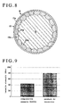
- the tensile strength of the heat resistant stainless steel wire "B” according to the present invention was found to be 800 MPa (as shown in Figure 9).
- the strength of a stainless steel wire heat treated without a covering alloy powder as a Comparative Example was found to be 455 MPa.
- the heat resistant stainless steel wire "B" according to the present invention is improved in strength by one or both of the thermal stress occurring from a difference in the coefficient of thermal expansion between the second layer 13b formed from an alloy layer of ferritic material on the surface of the stainless steel wire 12 and the austenitic stainless steel of the stainless steel wire 12, or the residual stress generated between the polycrystalline alloy layers on the surface of the stainless steel wire 12.
- Heat resistance tests were conducted on the heat resistant stainless steel wire "B" according to the present invention, a thin stainless steel wire formed from SUS304 as a first Comparative Example, and a thin stainless steel wire formed from FCH2 (Fe-Cr-Al alloy) as a second Comparative Example for 25 hours in atmosphere at a temperature of 1100°C.
- the tensile strength of the stainless steel wire of the first Comparative Example formed from SUS304 decreases to a level which is impossible to measure after about one hour of heating; the tensile strength of the stainless steel wire of the second Comparative Example formed from FCH2 (Fe-Cr-Al alloy) was 417 MPa; whereas the tensile strength of the heat resistant stainless steel wire "B" according to the present invention even after 25 hours of heating was 670 MPa.
- Figure 10 shows the relationship between the exposure time and the change (lowering) ratio of the tensile strength of the heat resistant stainless steel wire "B" according to the present invention and the stainless steel wire formed from FCH2 (Fe-Cr-Al alloy) of the second Comparative Example. It is evident that the tensile strength of the heat resistant stainless steel wire "B” according to the present invention decreases to a far lesser degree than the stainless steel wire formed from FCH2 (Fe-Cr-Al alloy) of the second Comparative Example.
- the afore-mentioned heat resistance test was conducted with various diameters of stainless steel wire 12 as the substrate metal with respect to the heat resistant stainless steel wire "B” according to the present invention and the stainless steel wire formed from FCH2 (Fe-Cr-Al alloy) of the second Comparative Example.
- the decrease in tensile strength of the heat resistant stainless steel wire "B” according to the present invention is smaller than that of the stainless steel wire formed from FCH2 (Fe-Cr-Al alloy) of the second Comparative Example for wire diameters up to 0.5 mm.
- the afore-mentioned heat resistance test was conducted with varying thicknesses of substrate metal with respect to heat resistant stainless steel strip "B” according to the present invention and stainless steel strip formed from FCH2 (Fe-Cr-Al alloy) as a second Comparative Example.
- the decrease in tensile strength of the heat resistant stainless steel strip "B” according to the present invention is smaller than that of the stainless steel strip formed from FCH2 (Fe-Cr-Al alloy) of the second Comparative Example for thicknesses up to 0.5 mm.
- Stainless steel wire or strip formed from FCH2 (Fe-Cr-Al alloy) of the second Comparative Example having a diameter of 0.2 mm or less is very difficult to subject to plastic working (such as stretching, rolling and bending).
- the heat resistant stainless steel wire and heat resistant stainless steel strip "B" according to the present invention can be worked plastically without any difficulty even if the diameter or thickness is made smaller by using stainless steel wire or strip having a relatively good processability.
- Figure 11 shows the relationship between the average diameter of the crystalline particles of the ferritic phase in the second layer 13b and the fracture elongation in the heat resistant stainless steel wire "B" according to the present invention. It is understood that when the average diameter of the crystalline particles of the second layer 13b exceeds 10 micron, the fracture elongation increases.
- Figure 12 shows the relationship between the average diameter of the crystalline particles of the aluminum-iron compound and the aluminum-nickel compound dispersed in the second layer 13b and the tensile strength of the heat resistant stainless steel wire "B" according to the present invention. It is understood that when the average diameter of the crystalline particles of the compounds dispersed in the second layer 13b is less than 1 micron, the tensile strength is materially enhanced.
- the heat treatment time of the heat resistant stainless steel wire "B” according to the present invention is excessively long, the crystals of the austenitic phase of the stainless steel wire 12 in the center portion of the heat resistant stainless steel wire “B” grow and the ferritic phase of the second layer 13b dissipates.
- a suitable heat treatment time is about two hours.
- the first layer 13a is formed to be thin because it is brittle.
- Alumina of the first layer 13a is high in heat resistance to prevent the second layer 13b from being oxidized.
- a plurality of samples having different thicknesses of the first layer 13a formed of a composite phase of aluminum and an aluminum-iron alloy were prepared using various heat treatment times to obtain heat resistant stainless steel wire "B” according to the present invention. Winding tests were conducted on the obtained heat resistant stainless steel wire "B” and the surface thereof analysed. It was found that when the thickness of the first layer 13a exceeds 10 micron, cracks occurred in the first layer 13a (as shown in Figure 13). From this viewpoint, it is preferable that the heat treatment time for obtaining the heat resistant stainless steel wire "B” according to the present invention is not too long.
- thin austenitic stainless steel wire as the substrate metal, from which carbide and martensite are much less likely to be produced during the heat treatment.
- An austenitic stainless steel wire having a chemical composition of by weight 0.15% or less of carbon, 15 to 26% of chrome, and 3.5 to 28% of nickel is particularly preferred.
- the carbide of the second layer 13b undesirably precipitates in the grain boundary and promotes brittleness.
Abstract
Description
- The present invention relates to heat resistant stainless steel wire or strip for an electric heater as used in a preheating plug for a diesel engine, and particularly to heat resistant stainless steel wire or strip in which the bonding forces of a covering layer relative to the substrate steel wire are strong.
- Methods for applying a ceramic-metal composite covering to the surface of a base material or substrate metal known to date include Chemical Vapor Deposition (CVD), Physical Vapor Deposition (PVD), Solgel, flame coating and the like.
- However, in the CVD method, materials for the substrate metal and the covering layer are restricted, and in the PVD method, the bonding force or adhesion force between the substrate metal and the covering layer is weak. Further, in the Solgel method, the bonding force or adhesion force between the substrate metal and the covering layer is weak, and it is difficult to form a covering layer whose thickness exceeds 1 micron. Particularly, it is necessary to finely roughen the surface of the substrate metal by shot blasting or the like before applying the covering layer. It is therefore very difficult to form a covering layer on metal parts such as a thin wire, a thin sheet, small articles, etc..
- Japanese Patent Application Laid-Open No. 287407/1993 discloses an example in which alloy powder such as nickel alloy, cobalt alloy, etc., is provided in firm contact with the surface of a ceramic powder such as relatively coarse silicon nitride, alumina, etc., in order to provide a ceramic based powder for covering the surface of a substrate metal such as a machining tool. However, such substrate metals have insufficient mechanical strength and the uses thereof are thus limited.
- On the other hand, stainless steel covered with aluminum by melt plating to provide enhanced heat resistance has been put to practical use. However, in a thin stainless steel wire or sheet covered with aluminum by melt plating, the aluminum alloy layer obtained by melt plating is brittle. Moreover, stainless steel as a substrate metal becomes brittle at high temperature. Likewise, an aluminum alloy layer obtained by diffusion treatment is also brittle, which alloy layer can be peeled off from the stainless steel wire or strip as a base material or substrate metal at high temperature. In addition, the substrate metal also becomes brittle.
- In view of the aforementioned problems, an aim of the present invention is to provide a heat resistant stainless steel wire or strip which has a strong bonding force relative to a covering layer.
- Another aim of the present invention is to provide a heat resistant stainless steel wire or strip in which a strong intermediate layer is formed between an aluminum covering layer and a substrate metal, thereby to enhance the heat resistance and the durability of the wire or strip.
- Accordingly, the present invention provides a heat resistant wire or strip comprising a stainless steel wire or strip containing chrome (Cr) covered with a covering layer formed of one of nickel (Ni) group alloy particles containing aluminum (Al) covered with ceramic particles or chrome (Cr) group alloy particles containing aluminum (Al) covered with ceramic particles.
- The present invention also provides a heat resistant wire or strip comprising a stainless steel wire or strip containing chrome (Cr) covered with a covering layer of one of nickel (Ni) group alloy particles containing aluminum (Al) covered with ceramic particles or chrome (Cr) group alloy particles containing aluminum (Al) covered with ceramic particles, and a fine ceramic layer covering said covering layer.
- The present invention further provides a heat resistant wire or strip comprising an austenitic stainless steel wire or strip, a first layer comprising aluminum and an iron-aluminum alloy formed as an outermost surface, and a second layer comprising an aluminum-iron compound and an aluminum-nickel compound dispersed in a ferritic stainless steel mainly comprising iron-chrome formed as an intermediate layer.
- In a preferred embodiment the thickness of the first layer is 10 micron or less, and the average diameter of the crystalline particles of the second layer is 10 to 30 micron.
- The heat resistant wire of this invention uses a thin stainless steel wire or strip as the substrate metal, in particular of circular and thin rectangular section.
- In a preferred embodiment a mixture of ceramic particles or powder having a uniform particle size distribution and an average particle diameter of 1 micron or less and alloy particles or powder is adhered to the surface of a thin steel wire or strip, as the substrate metal, by an organic solvent and then heat treated in vacuum to obtain the heat resistant steel wire or strip. By the heat treatment the ceramic and alloy powders are reduced by carbon in the organic solvent and deposited on the thin steel wire or strip.
- In a preferred embodiment, as the substrate metal, thin steel wire or strip containing, in addition to chrome (Cr), at least one of nickel (Ni), aluminum (Al) and yttrium (Y), that is, thin stainless steel wire is selected. As the ceramic powder, at least one of aluminum (Al), silicon (Si), magnesium (Mg), zirconium (Zr), barium (Ba) and titanium (Ti) can be selected. More specifically, oxides such as Al2O3, SiO2, Mg0, ZrO2, BaTiO3, TiO2, etc., can be selected. As the alloy powder, nickel (Ni) based alloy powder containing aluminum (Al), preferably Ni-Cr-Al alloy powder, can be selected.
- In order to improve the durability of the thin stainless steel wire or strip, the alloy powder of chrome and aluminum is bonded on the surface of the thin stainless steel wire or strip as the substrate metal using an adhesive and then heat treated for about two hours in vacuum at a temperature of 1100°C. With this treatment, a first layer of 10 micron or less in thickness comprising aluminum and an iron-aluminum alloy is formed as the outermost surface of the thin stainless steel wire or strip, a second layer of 20 micron or more in thickness comprising an aluminum-iron compound and an aluminum-nickel compound dispersed into a ferritic stainless steel mainly comprising iron-chrome is formed as an intermediate layer, and a thin austenitic based stainless steel wire or strip is present in the center portion of the heat resistant wire or strip.
- In a particularly preferred embodiment the mixture of ceramic powder and alloy powder is adhered to the surface of the substrate metal using an adhesive such as synthetic rubber and then heat treated in vacuum to obtain a heat resistant stainless steel wire or strip having a covering layer with a large bonding force relative to the substrate metal.
- In a preferred embodiment the chrome-aluminum particles are adhered to the surface of the thin austenitic stainless steel wire or strip which is then heat treated to obtain a heat resistant stainless steel wire or strip having a ferritic Fe-Cr-Ni-Al alloy layer on the surface thereof, which wire or strip has excellent heat resistance and tensile strength.
- As a substrate metal having a relatively good processability is used, the heat resistant stainless steel wire or strip according to the present invention can be readily worked plastically even if the wire diameter or strip thickness is small.
- Preferred embodiments of the present invention will now be described hereinbelow by way of example only with reference to the accompanying drawings, in which:
- Figure 1 is a schematic sectional view of a heat resistant stainless steel wire in accordance with a first embodiment of the present invention;
- Figure 2 is a fragmentary sectional view in enlarged scale of the heat resistant stainless steel wire of Figure 1;
- Figure 3 is a schematic sectional view of the heat resistant stainless steel wire of Figure 1 provided with a coating;
- Figure 4 is a graph showing the relationship between the diameter of the ceramic particles and the degree of covering by the covering layer in the heat resistant stainless steel wire according to the first embodiment of the present invention;
- Figure 5 is a graph showing the results of tensile strength tests performed on the heat resistant stainless steel wire according to the first embodiment of the present invention and Comparative Examples;
- Figure 6 is a graph showing the relationship between the addition of Al2O3 to the ceramic particles and the oxidation weighting of the heat resistant stainless steel wire according to the first embodiment of the present invention;
- Figure 7 is a graph showing the relationship between the addition of Al2O3 to the ceramic particles and the tensile strength of the heat resistant stainless steel wire according to the first embodiment of the present invention;
- Figure 8 is a schematic sectional view of a heat resistant stainless steel wire in accordance with a second embodiment of the present invention;
- Figure 9 is a block diagram showing the tensile strength of the heat resistant stainless steel wire according to the second embodiment of the present invention and a Comparative Example;
- Figure 10 is a graph showing the relationship between the tensile strength and exposure time at 1100°C of the heat resistant stainless steel wire according to the second embodiment of the present invention and a Comparative Example;
- Figure 11 is a graph showing the relationship between the average diameter of the crystalline particles and the fracture elongation of the ferritic phase in the second layer of the heat resistant stainless steel wire according to the second embodiment of the present invention;
- Figure 12 is a graph showing the relationship between the average diameter of the crystalline particles and the tensile strength of the second layer in the heat resistant stainless steel wire according to the second embodiment of the present invention; and
- Figure 13 is a graph showing the relationship between the thickness of the first layer and the rate of occurrence of cracks in the heat resistant stainless steel wire according to the second embodiment of the present invention.
- A heat resistant stainless steel wire in accordance with a first embodiment of the present invention (as shown in Figures 1 and 2) was fabricated as follows. A synthetic rubber based adhesive formed from acrylic rubber, an organic solvent, isohexane gas, etc., was coated, by spraying, on the surface of a thin
stainless steel wire 2 of 0.2 mm diameter as a substrate metal. A mixture of Ni-Cr-Al alloy powder 4 having an average particle diameter of 5 to 20 micron andceramic powder 6 such a Al2O3, SiO2, MgO, ZrO2, BaTiO3, TiO2, etc., having an average particle diameter of 0.3 to 1.0 micron was applied to the surface of the adhesive coated on the surface of thestainless steel wire 2. Subsequently, thestainless steel wire 2 was heated for about two hours under vacuum at a temperature of 1100 to 1300°C to obtain a heat resistant stainless steel wire "A" covered with particulate material. - The surface of the heat resistant stainless steel wire "A" covered with particulate material obtained according to the present invention was analyzed. The Ni-Cr-
Al alloy powder 4 and theceramic powder 6 covered, and were adhered to, the surface of thestainless steel wire 2, with thestainless steel wire 2 having the same shape and the covering particles having the same diameter as before being treated (as shown in Figure 1). Theparticles stainless steel wire 2 were not disposed one above the other but uniformly dispersed into a coveringlayer 10 as a substantially single layer. The coveringparticles - With regard to the
ceramic particles 6 covering the surface of thestainless steel wire 2, as shown in Figure 4 the particle size distribution becomes more uniform as the particle diameter becomes smaller, thereby rendering the coveringlayer 10 more uniform. It has been found from comparative tests that when the average diameter of theceramic particles 6 covering the surface of thestainless steel wire 2 exceeds 1 micron, theceramic particles 6 adhere only poorly to thestainless steel wire 2 and a part of the surface of thestainless steel wire 2 is not covered at all with particulate material. It has been further found that when only Ni-Cr-Al alloy particles are used as the particulate material for covering the surface of thestainless steel wire 2, agglomeration of the Ni-Cr-Al alloy particles occurs. - As a result of analysing sections of the heat resistant stainless steel wire "A" covered with particulate material according to the present invention, it has been found (as shown in Figure 2), that a
reaction layer 3 comprising constituent elements of thecovering particles stainless steel wire 2 is formed at the interface between thecovering particles stainless steel wire 2. This results from the fact that under vacuum the fineceramic particles 6 and the Ni-Cr-Al alloy particles 4 are reduced by carbon (C) contained in the organic solvent and react with thestainless steel wire 2 as the substrate metal. - For the evaluation of the adhesion between the
stainless steel wire 2 as the substrate metal and the coveringlayer 10 comprising thecovering particles particles layer 10 and detachment of thecovering particles particles stainless steel wire 2 are bonded together through thereaction layer 3 and theceramic particles 6 are not bonded to each other but are independent, as a consequence of which thermal stress is relieved. - Next, with respect to heat resistant stainless steel wires A1 - A5 covered with particulate material according to the present invention, which use, as the particulate material, Ni-Cr-Al alloy particles and ceramic particles such as Al2O3, TiO2, MgO, ZrO2, SiO2, BaTiO3, etc., and thin stainless steel wires B1 - B3 as Comparative Examples, heat resistant strength tests were conducted to determine the change in strength after exposure to atmosphere at a temperature of 1100°C for 25 hours. As shown in Figure 5, the tensile strength of the heat resistant stainless steel wires A1 - A5 according to the present invention was 300 MPa or more. On the other hand, the tensile strength of the uncovered stainless steel wire B1, the tensile strength of the stainless steel wire B2 covered with Al2O3 by the Solgel method, and the tensile strength of the stainless steel wire B3 covered with only Ni-Cr-Al alloy could not be measured after one hour of exposure, 10 hours of exposure, and 25 hours of exposure, respectively.
- With regard to the heat resistant stainless steel wire A1 covered with particulate material in which 5% by weight or more of Al2O3 particles were added to Ni-Cr-Al alloy particles, a heat resistant strength test, in which the heat resistant stainless steel wire A1 was exposed to atmosphere at a temperature of 1100°C for 25 hours, was conducted, after which an oxide layer on the surface of the stainless steel wire was analyzed. Chrome (Cr) and aluminum (Al) were detected in the oxide layer. On the other hand, iron (Fe) and chrome (Cr) were detected in an oxide layer on the surface of the stainless steel wire B3 having only Ni-Cr-Al alloy as the particulate material.
- It has been found by the afore-mentioned heat resistance strength test that when 5% by weight or more of Al2O3 particles is added to Ni-Cr-Al alloy particles, as the particulate material for covering the surface of the stainless steel wire, the oxidation weighting is reduced and the tensile strength after conducting the strength test is improved (as shown in Figures 6 and 7). The oxidation weighting PW is represented by PW=100(W1-W0)/W0, wherein W1 and W0 respectively represent the mass of the heat resistant stainless steel wire before and after the heat resistance strength test. It is considered from the afore-mentioned analysis and the heat resistance strength test what when Al2O3 particles are added to Ni-Cr-Al alloy particles, as the particulate material of the covering layer, the heat resistance strength is improved because the oxidation of iron (Fe) is suppressed.
- It has been found that the specific resistance of the surface of the heat resistant stainless steel wire "A" according to the present invention at ordinary room temperature was approximately 20 MΩ-cm, and particularly, the specific resistance of the surface of the heat resistant stainless steel wire A3 covered with particulate material including MgO was approximately 10 MΩ-cm even at a temperature of 1000°C.
- Next, a solgel coating was applied to the surface of the
covering layer 10 of the heat resistant stainless steel wire "A" covered with Ni-Cr-Al alloy particles 4 andceramic particles 6 of Al2O3, SiO2, MgO, ZrO2, BaTiO3 and TiO2, as the particulate material, using a coating solution prepared from commercially available metal alkoxide. In accordance with the conditions of solgel coating the heat resistant stainless steel wire "A" was dipped into the coating solution, raised therefrom, subjected to hydrolysis, and then heat treated in atmosphere at a temperature of 600°C (as shown in Figure 3). In a Comparative Example comprising thin stainless steel wire not covered with particulate material, the coating was peeled off simply, whereas in the heat resistant stainless steel wire "A" covered with particulate material according to the present invention, thecoating layer 8 could not be peeled off when the thickness thereof was from 1 to 2 micron. It is considered that the contact strength of thecoating layer 8 is enhanced due to an anchoring effect of theceramic particles 6 adhered to the surface of thestainless steel wire 2. - A heat resistant stainless steel wire in accordance with a second embodiment of the present invention was fabricated as follows. A synthetic rubber based adhesive formed from acrylic rubber, an organic solvent, isohexane gas, etc., was coated, by spraying, on the surface of a thin austenitic stainless steel wire (SUS304) 12 having a diameter of 0.25 mm. Alloy powder comprising by
weight 50% of chrome and 50% of aluminum was applied to the surface of the synthetic rubber based adhesive and then subjected to a heat treatment for about two hours under vacuum at a temperature of 1100°C. - A section of the heat resistant stainless steel wire "B" according to the present invention, obtained as above-described, was analyzed. A Fe-Cr-Ni-
Al alloy layer 13 having a fine dispersed phase ofthickness 10 to 50 micron was formed on the surface of the stainless steel wire 12 (as shown in Figure 8). It has been found that thealloy layer 13 on the surface of the stainless steel wire 12 is not a single layer but comprises an alloy layer of 10 micron or less in thickness comprising aluminum and an aluminum-iron alloy, that is, afirst layer 13a formed on the outermost surface, and an alloy layer of 20 micron or more in thickness in which an aluminum-iron compound and an aluminum-nickel compound are dispersed in ferriticcrystalline grains 14a of 10 to 30 micron in particle diameter, that is, asecond layer 13b formed internally of thefirst layer 13a. The average diameter of the crystalline particles of the aluminum-iron compound and the aluminum-nickel compound was 1 micron or less. Austenitic stainless steel having crystalline particles of average diameter of 20 to 50 micron is present in a center portion of the section of the heat resistant stainless steel wire "B". Thesecond layer 13b of ferritic material is soft as compared with the iron-aluminum alloy of thefirst layer 13a. - The tensile strength of the heat resistant stainless steel wire "B" according to the present invention and a Comparative Example were measured. The tensile strength of the heat resistant stainless steel wire "B" according to the present invention was found to be 800 MPa (as shown in Figure 9). The strength of a stainless steel wire heat treated without a covering alloy powder as a Comparative Example (corresponding to the substrate metal of the present invention) was found to be 455 MPa. It is considered that the heat resistant stainless steel wire "B" according to the present invention is improved in strength by one or both of the thermal stress occurring from a difference in the coefficient of thermal expansion between the
second layer 13b formed from an alloy layer of ferritic material on the surface of the stainless steel wire 12 and the austenitic stainless steel of the stainless steel wire 12, or the residual stress generated between the polycrystalline alloy layers on the surface of the stainless steel wire 12. - Heat resistance tests were conducted on the heat resistant stainless steel wire "B" according to the present invention, a thin stainless steel wire formed from SUS304 as a first Comparative Example, and a thin stainless steel wire formed from FCH2 (Fe-Cr-Al alloy) as a second Comparative Example for 25 hours in atmosphere at a temperature of 1100°C. The tensile strength of the stainless steel wire of the first Comparative Example formed from SUS304 decreases to a level which is impossible to measure after about one hour of heating; the tensile strength of the stainless steel wire of the second Comparative Example formed from FCH2 (Fe-Cr-Al alloy) was 417 MPa; whereas the tensile strength of the heat resistant stainless steel wire "B" according to the present invention even after 25 hours of heating was 670 MPa.
- Figure 10 shows the relationship between the exposure time and the change (lowering) ratio of the tensile strength of the heat resistant stainless steel wire "B" according to the present invention and the stainless steel wire formed from FCH2 (Fe-Cr-Al alloy) of the second Comparative Example. It is evident that the tensile strength of the heat resistant stainless steel wire "B" according to the present invention decreases to a far lesser degree than the stainless steel wire formed from FCH2 (Fe-Cr-Al alloy) of the second Comparative Example.
- The afore-mentioned heat resistance test was conducted with various diameters of stainless steel wire 12 as the substrate metal with respect to the heat resistant stainless steel wire "B" according to the present invention and the stainless steel wire formed from FCH2 (Fe-Cr-Al alloy) of the second Comparative Example. The decrease in tensile strength of the heat resistant stainless steel wire "B" according to the present invention is smaller than that of the stainless steel wire formed from FCH2 (Fe-Cr-Al alloy) of the second Comparative Example for wire diameters up to 0.5 mm.
- Further, the afore-mentioned heat resistance test was conducted with varying thicknesses of substrate metal with respect to heat resistant stainless steel strip "B" according to the present invention and stainless steel strip formed from FCH2 (Fe-Cr-Al alloy) as a second Comparative Example. The decrease in tensile strength of the heat resistant stainless steel strip "B" according to the present invention is smaller than that of the stainless steel strip formed from FCH2 (Fe-Cr-Al alloy) of the second Comparative Example for thicknesses up to 0.5 mm.
- Stainless steel wire or strip formed from FCH2 (Fe-Cr-Al alloy) of the second Comparative Example having a diameter of 0.2 mm or less is very difficult to subject to plastic working (such as stretching, rolling and bending). On the other hand, the heat resistant stainless steel wire and heat resistant stainless steel strip "B" according to the present invention can be worked plastically without any difficulty even if the diameter or thickness is made smaller by using stainless steel wire or strip having a relatively good processability.
- Figure 11 shows the relationship between the average diameter of the crystalline particles of the ferritic phase in the
second layer 13b and the fracture elongation in the heat resistant stainless steel wire "B" according to the present invention. It is understood that when the average diameter of the crystalline particles of thesecond layer 13b exceeds 10 micron, the fracture elongation increases. - Figure 12 shows the relationship between the average diameter of the crystalline particles of the aluminum-iron compound and the aluminum-nickel compound dispersed in the
second layer 13b and the tensile strength of the heat resistant stainless steel wire "B" according to the present invention. It is understood that when the average diameter of the crystalline particles of the compounds dispersed in thesecond layer 13b is less than 1 micron, the tensile strength is materially enhanced. - When the heat treatment time of the heat resistant stainless steel wire "B" according to the present invention is excessively long, the crystals of the austenitic phase of the stainless steel wire 12 in the center portion of the heat resistant stainless steel wire "B" grow and the ferritic phase of the
second layer 13b dissipates. A suitable heat treatment time is about two hours. Preferably, thefirst layer 13a is formed to be thin because it is brittle. Alumina of thefirst layer 13a is high in heat resistance to prevent thesecond layer 13b from being oxidized. - A plurality of samples having different thicknesses of the
first layer 13a formed of a composite phase of aluminum and an aluminum-iron alloy were prepared using various heat treatment times to obtain heat resistant stainless steel wire "B" according to the present invention. Winding tests were conducted on the obtained heat resistant stainless steel wire "B" and the surface thereof analysed. It was found that when the thickness of thefirst layer 13a exceeds 10 micron, cracks occurred in thefirst layer 13a (as shown in Figure 13). From this viewpoint, it is preferable that the heat treatment time for obtaining the heat resistant stainless steel wire "B" according to the present invention is not too long. - In the present invention, it is preferable to use thin austenitic stainless steel wire as the substrate metal, from which carbide and martensite are much less likely to be produced during the heat treatment. An austenitic stainless steel wire having a chemical composition of by weight 0.15% or less of carbon, 15 to 26% of chrome, and 3.5 to 28% of nickel is particularly preferred. When the composition ratio of carbon increases, the carbide of the
second layer 13b undesirably precipitates in the grain boundary and promotes brittleness. - It will be understood that the present invention is not limited to the above-described embodiments, but can be modified in many different ways within the scope of the appended claims.
Claims (13)
- A heat resistant wire or strip comprising a stainless steel wire or strip containing chrome (Cr) covered with a covering layer formed of one of nickel (Ni) group alloy particles containing aluminum (Al) covered with ceramic particles or chrome (Cr) group alloy particles containing aluminum (Al) covered with ceramic particles.
- A heat resistant wire or strip according to claim 1, wherein said stainless steel further contains at least one of nickel (Ni), aluminum (Al) and yttrium (Y).
- A heat resistant wire or strip according to claim 1 or 2, wherein alloy particles of said covering layer are bonded to each other, and the ceramic particles of said covering layer are independent without being sintered and adhered to the surface of said alloy particles and said stainless steel wire or strip.
- A heat resistant wire or strip according to any of claims 1 to 3, wherein the ceramic particles of said covering layer contain at least one of aluminum (Al), silicon (Si), magnesium (Mg), zirconium (Zr), barium (Ba) and titanium (Ti), 5% weight or more of which is contained in said covering layer thereof.
- A heat resistant stainless steel wire or strip according to any of claims 1 to 4, wherein the ceramic particles of said covering layer have an average particle diameter of 1 micron or less.
- A heat resistant wire or strip comprising a stainless steel wire or strip containing chrome (Cr) covered with a covering layer of one of nickel (Ni) group alloy particles containing aluminum (Al) covered with ceramic particles or chrome (Cr) group alloy particles containing aluminum (Al) covered with ceramic particles, and a fine ceramic layer covering said covering layer.
- A heat resistant wire or strip comprising an austenitic stainless steel wire or strip, a first layer comprising aluminum and an iron-aluminum alloy formed as an outermost surface, and a second layer comprising an aluminum-iron compound and an aluminum-nickel compound dispersed in a ferritic stainless steel mainly comprising iron-chrome formed as an intermediate layer.
- A heat resistant stainless steel wire or strip according to claim 7, wherein the thickness of said first layer is 10 micron or less.
- A heat resistant stainless steel wire or strip according to claim 7 or 8, wherein the average diameter of the crystalline particles of said second layer is 10 to 30 micron.
- A heat resistant wire or strip according to any of claims 7 to 9, wherein the average diameter of the crystalline particles of the aluminum-iron and aluminum-nickel compounds dispersed in said second layer is 1 micron or less.
- A heat resistant wire or strip according to any of claims 7 to 10, wherein said austenitic stainless steel contains by weight 0.15% or less of carbon, 15 to 26% of chrome, and 3.5 to 28% of nickel.
- A heat resistant wire or strip according to any of claims 7 to 11, wherein the diameter or thickness of said wire or strip is 0.5 mm or less.
- A heat resistant wire or strip according to any of claims 7 to 12, wherein said alloy particles are particles deposited on the stainless steel wire or strip.
Priority Applications (1)
| Application Number | Priority Date | Filing Date | Title |
|---|---|---|---|
| EP98201850A EP0874062A3 (en) | 1995-11-06 | 1996-11-04 | Heat resistant stainless steel wire or strip |
Applications Claiming Priority (4)
| Application Number | Priority Date | Filing Date | Title |
|---|---|---|---|
| JP313554/95 | 1995-11-06 | ||
| JP31355495A JPH09125106A (en) | 1995-11-06 | 1995-11-06 | Metal coated with granular material |
| JP3438796A JPH09209118A (en) | 1996-01-29 | 1996-01-29 | Heat resistant coated stainless steel |
| JP34387/96 | 1996-01-29 |
Related Child Applications (1)
| Application Number | Title | Priority Date | Filing Date |
|---|---|---|---|
| EP98201850A Division EP0874062A3 (en) | 1995-11-06 | 1996-11-04 | Heat resistant stainless steel wire or strip |
Publications (2)
| Publication Number | Publication Date |
|---|---|
| EP0771882A1 true EP0771882A1 (en) | 1997-05-07 |
| EP0771882B1 EP0771882B1 (en) | 1999-03-03 |
Family
ID=26373187
Family Applications (2)
| Application Number | Title | Priority Date | Filing Date |
|---|---|---|---|
| EP96307965A Expired - Lifetime EP0771882B1 (en) | 1995-11-06 | 1996-11-04 | Heat resistance stainless steel wire or strip |
| EP98201850A Ceased EP0874062A3 (en) | 1995-11-06 | 1996-11-04 | Heat resistant stainless steel wire or strip |
Family Applications After (1)
| Application Number | Title | Priority Date | Filing Date |
|---|---|---|---|
| EP98201850A Ceased EP0874062A3 (en) | 1995-11-06 | 1996-11-04 | Heat resistant stainless steel wire or strip |
Country Status (3)
| Country | Link |
|---|---|
| US (1) | US5976708A (en) |
| EP (2) | EP0771882B1 (en) |
| DE (1) | DE69601612T2 (en) |
Cited By (2)
| Publication number | Priority date | Publication date | Assignee | Title |
|---|---|---|---|---|
| EP1498180A2 (en) * | 2003-07-18 | 2005-01-19 | Rhodius GmbH | Metallic catalyst support and its manufacturing |
| CN115233169A (en) * | 2022-06-22 | 2022-10-25 | 苏州六九新材料科技有限公司 | Aluminum-based tubular target and preparation method thereof |
Families Citing this family (3)
| Publication number | Priority date | Publication date | Assignee | Title |
|---|---|---|---|---|
| DE19942234C1 (en) * | 1999-09-03 | 2001-03-01 | Krupp Vdm Gmbh | Process for the production of multi-phase composite materials and use of the composite material |
| DE19957646A1 (en) * | 1999-11-30 | 2001-05-31 | Krupp Vdm Gmbh | Alloy production comprises coating base material made of austenitic nickel-based alloy or cobalt-based alloy or special steel on one or both sides with layer of aluminum or aluminum alloy |
| CN114411141B (en) * | 2022-01-19 | 2023-07-07 | 西部宝德科技股份有限公司 | Nest-shaped stainless steel porous material and preparation method thereof |
Citations (8)
| Publication number | Priority date | Publication date | Assignee | Title |
|---|---|---|---|---|
| US2934670A (en) * | 1956-11-05 | 1960-04-26 | Columbia Broadcasting Syst Inc | Electron tubes and method of making same |
| JPS55110830A (en) * | 1979-02-20 | 1980-08-26 | Matsushita Electric Ind Co Ltd | Ignition heater |
| JPS58140411A (en) * | 1982-02-15 | 1983-08-20 | Toyota Motor Corp | Ignition heater for collector of soot in exhaust gas of motor car and its manufacture |
| JPS60216A (en) * | 1983-06-15 | 1985-01-05 | Ngk Spark Plug Co Ltd | Glow plug |
| EP0475427A1 (en) * | 1990-09-14 | 1992-03-18 | Matsushita Electric Industrial Co., Ltd. | A heating element and a method for manufacturing the same |
| JPH06241450A (en) * | 1993-02-10 | 1994-08-30 | Tanaka Kikinzoku Kogyo Kk | Heater wire for battery type lighter |
| JPH0719473A (en) * | 1993-02-05 | 1995-01-20 | Akira Takeuchi | Battery cell lighter |
| EP0673493A1 (en) * | 1993-10-12 | 1995-09-27 | Beru Werk Ruprecht Gmbh Co A | Glow plug. |
Family Cites Families (21)
| Publication number | Priority date | Publication date | Assignee | Title |
|---|---|---|---|---|
| US4141760A (en) * | 1972-11-06 | 1979-02-27 | Alloy Surfaces Company, Inc. | Stainless steel coated with aluminum |
| FR2182614B1 (en) * | 1972-03-17 | 1978-05-05 | Louyot Comptoir Lyon Alemand | |
| US3807030A (en) * | 1972-12-27 | 1974-04-30 | Chrysler Corp | Method of preparing oxidation resistant materials |
| US4292208A (en) * | 1974-05-03 | 1981-09-29 | Alloy Surfaces Company, Inc. | Diffusion coating combinations |
| US4977036A (en) * | 1979-03-30 | 1990-12-11 | Alloy Surfaces Company, Inc. | Coating and compositions |
| JPS5693869A (en) * | 1979-12-28 | 1981-07-29 | Nippon Steel Corp | Preparation of steel material having al diffused layer |
| JPS56112459A (en) * | 1980-02-08 | 1981-09-04 | Hitachi Ltd | Cr-al coating method |
| US5077257A (en) * | 1989-11-21 | 1991-12-31 | Alloy Surfaces Surfaces Company, Inc. | Diffusion-coated metals |
| US5182078A (en) * | 1980-07-28 | 1993-01-26 | Alloy Surfaces Company, Inc. | Metal treatment |
| US4655852A (en) * | 1984-11-19 | 1987-04-07 | Rallis Anthony T | Method of making aluminized strengthened steel |
| US4686155A (en) * | 1985-06-04 | 1987-08-11 | Armco Inc. | Oxidation resistant ferrous base foil and method therefor |
| US5066549A (en) * | 1986-05-20 | 1991-11-19 | Armco Inc. | Hot dip aluminum coated chromium alloy steel |
| US4885215A (en) * | 1986-10-01 | 1989-12-05 | Kawasaki Steel Corp. | Zn-coated stainless steel welded pipe |
| DE3882769T2 (en) * | 1987-03-31 | 1993-11-11 | Nippon Steel Corp | Corrosion-resistant plated steel strip and process for its manufacture. |
| US4835010A (en) * | 1987-06-08 | 1989-05-30 | Exxon Research And Engineering Company | Aluminide dispersed ferrite diffusion coating on austenitic stainless steel substrates |
| US4929473A (en) * | 1987-07-30 | 1990-05-29 | Intevep, S. A. | Corrosion resistance of low carbon steels in a vanadium, sulfur and sodium environment at high temperatures |
| US5372886A (en) * | 1989-03-28 | 1994-12-13 | Sumitomo Electric Industries, Ltd. | Insulated wire with an intermediate adhesion layer and an insulating layer |
| US5262033A (en) * | 1989-05-18 | 1993-11-16 | Nisshin Steel Co., Ltd. | Apparatus for the continuous etchings and aluminum plating of stainless steel strips |
| KR940001346B1 (en) * | 1991-12-30 | 1994-02-19 | 포항종합제철 주식회사 | Aluminum diffusion coating layer of heat resisting stainless steel and method for forming the same |
| JPH05287407A (en) * | 1992-04-08 | 1993-11-02 | Kawaguchi Seiko Kk | Production of ceramic powder coated with metal on surface for powder metallurty |
| JPH06260178A (en) * | 1993-02-26 | 1994-09-16 | Kawasaki Heavy Ind Ltd | Device material anti-corrosive covering method for molten salt and anti-corrosive covering material |
-
1996
- 1996-11-01 US US08/742,925 patent/US5976708A/en not_active Expired - Fee Related
- 1996-11-04 EP EP96307965A patent/EP0771882B1/en not_active Expired - Lifetime
- 1996-11-04 DE DE69601612T patent/DE69601612T2/en not_active Expired - Fee Related
- 1996-11-04 EP EP98201850A patent/EP0874062A3/en not_active Ceased
Patent Citations (8)
| Publication number | Priority date | Publication date | Assignee | Title |
|---|---|---|---|---|
| US2934670A (en) * | 1956-11-05 | 1960-04-26 | Columbia Broadcasting Syst Inc | Electron tubes and method of making same |
| JPS55110830A (en) * | 1979-02-20 | 1980-08-26 | Matsushita Electric Ind Co Ltd | Ignition heater |
| JPS58140411A (en) * | 1982-02-15 | 1983-08-20 | Toyota Motor Corp | Ignition heater for collector of soot in exhaust gas of motor car and its manufacture |
| JPS60216A (en) * | 1983-06-15 | 1985-01-05 | Ngk Spark Plug Co Ltd | Glow plug |
| EP0475427A1 (en) * | 1990-09-14 | 1992-03-18 | Matsushita Electric Industrial Co., Ltd. | A heating element and a method for manufacturing the same |
| JPH0719473A (en) * | 1993-02-05 | 1995-01-20 | Akira Takeuchi | Battery cell lighter |
| JPH06241450A (en) * | 1993-02-10 | 1994-08-30 | Tanaka Kikinzoku Kogyo Kk | Heater wire for battery type lighter |
| EP0673493A1 (en) * | 1993-10-12 | 1995-09-27 | Beru Werk Ruprecht Gmbh Co A | Glow plug. |
Non-Patent Citations (5)
| Title |
|---|
| PATENT ABSTRACTS OF JAPAN vol. 004, no. 161 (M - 040) 11 November 1980 (1980-11-11) * |
| PATENT ABSTRACTS OF JAPAN vol. 007, no. 257 (M - 256) 16 November 1983 (1983-11-16) * |
| PATENT ABSTRACTS OF JAPAN vol. 009, no. 111 (M - 379) 15 May 1985 (1985-05-15) * |
| PATENT ABSTRACTS OF JAPAN vol. 018, no. 628 (M - 1713) 30 November 1994 (1994-11-30) * |
| PATENT ABSTRACTS OF JAPAN vol. 95, no. 001 * |
Cited By (4)
| Publication number | Priority date | Publication date | Assignee | Title |
|---|---|---|---|---|
| EP1498180A2 (en) * | 2003-07-18 | 2005-01-19 | Rhodius GmbH | Metallic catalyst support and its manufacturing |
| EP1498180A3 (en) * | 2003-07-18 | 2005-02-23 | Rhodius GmbH | Metallic catalyst support and its manufacturing |
| CN115233169A (en) * | 2022-06-22 | 2022-10-25 | 苏州六九新材料科技有限公司 | Aluminum-based tubular target and preparation method thereof |
| CN115233169B (en) * | 2022-06-22 | 2023-09-05 | 苏州六九新材料科技有限公司 | Aluminum-based tubular target material and preparation method thereof |
Also Published As
| Publication number | Publication date |
|---|---|
| EP0874062A2 (en) | 1998-10-28 |
| EP0771882B1 (en) | 1999-03-03 |
| US5976708A (en) | 1999-11-02 |
| EP0874062A3 (en) | 1999-09-08 |
| DE69601612D1 (en) | 1999-04-08 |
| DE69601612T2 (en) | 1999-09-09 |
Similar Documents
| Publication | Publication Date | Title |
|---|---|---|
| CA1055326A (en) | Platinum-rhodium-containing high temperature alloy coating | |
| EP0215554B1 (en) | Method of producing brazing metals | |
| JP4519387B2 (en) | Thermal spray coating cermet powder and thermal spray coating roll with excellent build-up resistance | |
| EP0185603B1 (en) | Improved durability metallic-ceramic turbine air seals | |
| JP3356889B2 (en) | Hearth roll with excellent durability | |
| JPH0967662A (en) | Ceramic-coated member | |
| Oshida et al. | Titanium-porcelain system Part I: Oxidation kinetics of nitrided pure titanium, simulated to porcelain firing process | |
| JPH06173009A (en) | Coated cemented carbide excellent in wear resistance and its production | |
| EP0771882B1 (en) | Heat resistance stainless steel wire or strip | |
| JPH08268799A (en) | Preparation of tool insert brazable in air and insert prepared thereby | |
| Turker et al. | Oxidation behavior of three commercial ODS alloys at 1200 C | |
| Pérez et al. | Oxidation behavior of a Ni 3 Al PM alloy | |
| US6309699B2 (en) | Method of producing a metallic part exhibiting excellent oxidation resistance | |
| Pérez et al. | The influence of the alloy microstructure on the oxidation behavior of Ti–46Al–1Cr–0.2 Si Alloy | |
| JP2823169B2 (en) | Coil spring and its manufacturing method | |
| JP3081765B2 (en) | Carbon member and method of manufacturing the same | |
| JP3403460B2 (en) | Method for producing carbon material having non-oxide ceramic spray coating | |
| AU696386B2 (en) | Method of manufacturing high temperature resistant shaped parts | |
| JP3129383B2 (en) | Oxide-coated silicon carbide material and its manufacturing method | |
| US4902576A (en) | High temperature sliding element and method for preventing high temperature sliding wear | |
| JPS6033364A (en) | Hearth roll for heat treating furnace and preparation thereof | |
| EP0252728B1 (en) | Metallic slide members to be used with ceramic slide members and sliding assemblies using the same | |
| JP4032654B2 (en) | Surface coating material with excellent pick-up resistance and high-temperature wear resistance | |
| JPH05263212A (en) | Heat-resistant coating | |
| JP2693180B2 (en) | Stainless steel plate with excellent water repellency |
Legal Events
| Date | Code | Title | Description |
|---|---|---|---|
| PUAI | Public reference made under article 153(3) epc to a published international application that has entered the european phase |
Free format text: ORIGINAL CODE: 0009012 |
|
| AK | Designated contracting states |
Kind code of ref document: A1 Designated state(s): DE FR GB |
|
| 17P | Request for examination filed |
Effective date: 19970823 |
|
| 17Q | First examination report despatched |
Effective date: 19980119 |
|
| GRAG | Despatch of communication of intention to grant |
Free format text: ORIGINAL CODE: EPIDOS AGRA |
|
| GRAG | Despatch of communication of intention to grant |
Free format text: ORIGINAL CODE: EPIDOS AGRA |
|
| GRAH | Despatch of communication of intention to grant a patent |
Free format text: ORIGINAL CODE: EPIDOS IGRA |
|
| GRAH | Despatch of communication of intention to grant a patent |
Free format text: ORIGINAL CODE: EPIDOS IGRA |
|
| GRAA | (expected) grant |
Free format text: ORIGINAL CODE: 0009210 |
|
| AK | Designated contracting states |
Kind code of ref document: B1 Designated state(s): DE FR GB |
|
| ET | Fr: translation filed | ||
| REF | Corresponds to: |
Ref document number: 69601612 Country of ref document: DE Date of ref document: 19990408 |
|
| PLBE | No opposition filed within time limit |
Free format text: ORIGINAL CODE: 0009261 |
|
| STAA | Information on the status of an ep patent application or granted ep patent |
Free format text: STATUS: NO OPPOSITION FILED WITHIN TIME LIMIT |
|
| 26N | No opposition filed | ||
| PGFP | Annual fee paid to national office [announced via postgrant information from national office to epo] |
Ref country code: GB Payment date: 20011029 Year of fee payment: 6 Ref country code: FR Payment date: 20011029 Year of fee payment: 6 |
|
| PGFP | Annual fee paid to national office [announced via postgrant information from national office to epo] |
Ref country code: DE Payment date: 20011219 Year of fee payment: 6 |
|
| REG | Reference to a national code |
Ref country code: GB Ref legal event code: IF02 |
|
| PG25 | Lapsed in a contracting state [announced via postgrant information from national office to epo] |
Ref country code: GB Free format text: LAPSE BECAUSE OF NON-PAYMENT OF DUE FEES Effective date: 20021104 |
|
| PG25 | Lapsed in a contracting state [announced via postgrant information from national office to epo] |
Ref country code: DE Free format text: LAPSE BECAUSE OF NON-PAYMENT OF DUE FEES Effective date: 20030603 |
|
| GBPC | Gb: european patent ceased through non-payment of renewal fee | ||
| PG25 | Lapsed in a contracting state [announced via postgrant information from national office to epo] |
Ref country code: FR Free format text: LAPSE BECAUSE OF NON-PAYMENT OF DUE FEES Effective date: 20030731 |
|
| REG | Reference to a national code |
Ref country code: FR Ref legal event code: ST |