EP0771401B1 - Fülleinrichtung für isoliermaterial - Google Patents
Fülleinrichtung für isoliermaterial Download PDFInfo
- Publication number
- EP0771401B1 EP0771401B1 EP95923357A EP95923357A EP0771401B1 EP 0771401 B1 EP0771401 B1 EP 0771401B1 EP 95923357 A EP95923357 A EP 95923357A EP 95923357 A EP95923357 A EP 95923357A EP 0771401 B1 EP0771401 B1 EP 0771401B1
- Authority
- EP
- European Patent Office
- Prior art keywords
- tube
- filling
- insulation
- interior space
- feeder
- Prior art date
- Legal status (The legal status is an assumption and is not a legal conclusion. Google has not performed a legal analysis and makes no representation as to the accuracy of the status listed.)
- Expired - Lifetime
Links
Images

Classifications
-
- F—MECHANICAL ENGINEERING; LIGHTING; HEATING; WEAPONS; BLASTING
- F16—ENGINEERING ELEMENTS AND UNITS; GENERAL MEASURES FOR PRODUCING AND MAINTAINING EFFECTIVE FUNCTIONING OF MACHINES OR INSTALLATIONS; THERMAL INSULATION IN GENERAL
- F16L—PIPES; JOINTS OR FITTINGS FOR PIPES; SUPPORTS FOR PIPES, CABLES OR PROTECTIVE TUBING; MEANS FOR THERMAL INSULATION IN GENERAL
- F16L59/00—Thermal insulation in general
- F16L59/04—Arrangements using dry fillers, e.g. using slag wool
-
- F—MECHANICAL ENGINEERING; LIGHTING; HEATING; WEAPONS; BLASTING
- F16—ENGINEERING ELEMENTS AND UNITS; GENERAL MEASURES FOR PRODUCING AND MAINTAINING EFFECTIVE FUNCTIONING OF MACHINES OR INSTALLATIONS; THERMAL INSULATION IN GENERAL
- F16L—PIPES; JOINTS OR FITTINGS FOR PIPES; SUPPORTS FOR PIPES, CABLES OR PROTECTIVE TUBING; MEANS FOR THERMAL INSULATION IN GENERAL
- F16L59/00—Thermal insulation in general
- F16L59/14—Arrangements for the insulation of pipes or pipe systems
Definitions
- double tube assemblies wherein an insulation is arranged in the interior space between an inner tube and an outer tube surrounding said inner tube.
- Such tube assemblies are used for a very wide variety of purposes, for instance for conducting warm or cold fluids like liquids, air or smoke.
- Such assemblies often comprise individual shorter modules to compose a tubing of a desired length and form.
- a set of insulating tubes is known from our earlier Finnish patent No. 90590, wherein the set comprises outer tubes which surround inner tubes and end flanges closing the interior space between said tubes, said interior space being filled with an insulation material, especially blown insulation wool or the like.
- Each module in this set comprises mating end flanges by which said tube modules can be interconnected.
- said tube further comprises mating male and female portions.
- the inventive method consists in initially bringing one or several openings located in said end flange to register with parallel filling means functioning in pairs, after which tube assembly and said filling means functioning in pairs are brought in a mutually relative movement so that at least an end of a feeder tube is located at that location in the interior space of said tube assembly, from which the filling operation starts.
- said insulation material is brought to flow with a flow of fluid along one of said filling means or feeder tube into said interior space.
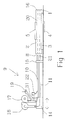
- an arrangement according to the invention suitably comprises an insulation procedure table 1, at one end of which there are placed tube assemblies 2 yet to be filled and at the opposite end thereof, respectively, are placed filled tube assemblies to be taken to storage.
- Said insulation procedure table 1 favorably comprises hoisting means which, according to a favorable embodiment of the invention, lift the empty tube assembly to be weighed prior to the filling procedure.
- said hoisting means are shown as roller type supports 3 which favorably are connected to a balance means generally shown as reference 4, suitably to a balance sensor which functions under said filling procedure table 1.
- a special characteristic of the invention resides therein that a uniform filling can be achieved also when the tubes are in a horizontal position and remain in position during the whole filling procedure, which considerably facilitates the handling of said tube assemblies 2.
- making sure of the filling degree also comprises the control of the pressure in the feeding blower tube 10, in which case a pressure sensor 31 is arranged to cut off the blowing and feeding of insulation material only at the stage when a certain counter pressure is achieved in the tube.
- a pressure sensor 31 is arranged to cut off the blowing and feeding of insulation material only at the stage when a certain counter pressure is achieved in the tube.
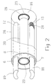
- the pre-fabricated tube assembly 2 to be filled comprises two filling openings 6 and 7, which suitably are located in an opposed disposition at at least one end flange 8, i.e. a flange which is arranged for the filling procedure, as is shown in more detail in Figures 2 and 3.
- a filler means 9 comprises at least on set of filler means functioning in pairs, i.e. an insulation feeding tube 10 and a pressure balancing or suction tube 11. At least one of the ends of said tubes, i.e. the end portion 12 of said feeding tube 10, and, according to one embodiment of the invention, also the end 13 of said suction tube, are movable with respect to said tube assembly 2.
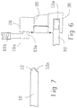
- Figure 6 discloses a corresponding arrangement wherein said end 13 of a suction tube 11a is arranged directly in an opening 6 in said flange 8 of said tube assembly 2, in which case said suction tube 11a in practice does not extend essentially at all into said tube assembly 2 but it is arranged through a suitably flexible tube portion llb separate from the other arrangement at the location of said opening in said flange 8.
- said end 12 of said feeder tube 10 is shaped so that a nozzle opening 12a has an inclined direction with respect to the general extent of said feeder tube 10 and said tube assembly 2. This is more clearly shown in Figure 7, wherein the end of said tube is rounded and the discharge opening 12a is located in the flank of said tube.
- both tube ends 12, 13 are located essentially at an equal distance (counted from the end flanges 8, 16 of said tube) the main air stream will occur at a very distinct area, i.e. so that said air stream and the insulation traveling therewith will remain essentially in a disk shaped transversal position when seen in the longitudinal direction of said tube 2 to be filled.
- the distribution of insulation or the like filler can be very well controlled, despite the fact that the filling procedure advances essentially in the horizontal direction and without moving said filling means 9 or said tube assembly to be filled, in a tangential direction with respect to the central axis of the procedure,
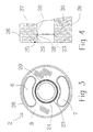
- said holes are especially capable of letting a certain portion of the insulation 27 transporting fluid to flow directly out just at said end flanges 8 and/or 16 of said tube 2, where the even distribution of insulation is at most difficult and where, on the other hand, the uniformity of the insulation 27 is most important.
- said holes 24 may be at least partly replaced with on or several outlet openings 7a located at the flange 16 which is opposite to the filling end, said outlet comprising a suitably detachable screen 21a.
- said opening 7a is further connected to an extra suction arrangement.
- said outlet openings are covered with a closing plate in a similar manner to said openings 6 and 7.
- Figure 4 further discloses that the extension portion 28 of said inner tube 20 favorably is realized in such a way that it comprises a bush portion 29 in connection with the end flange, over which portion said inner tube 20 can be pushed with its slightly enlarged collar portion 30.
- the inner tube 20 will in practice be quite smooth and thus it does not collect dust or soot but permits the undisturbed passage of the medium which flows in the tube.
Landscapes
- Engineering & Computer Science (AREA)
- General Engineering & Computer Science (AREA)
- Mechanical Engineering (AREA)
- Manufacturing Of Electric Cables (AREA)
- Thermal Insulation (AREA)
- Processing And Handling Of Plastics And Other Materials For Molding In General (AREA)
- Superconductors And Manufacturing Methods Therefor (AREA)
- Insulating Bodies (AREA)
- Insulators (AREA)
- Inorganic Insulating Materials (AREA)
Claims (10)
- Anordnung zur Befüllung des Innenraumes zwischen Rohren mit einem Isoliermaterial (27) oder ähnlichem, insbesondere mit geblasener Isolierwolle oder einem entsprechenden Material, insbesondere bei einer Rohrbaugruppe (2), die ein inneres Rohr (20) und einen äußeren rohrförmigen Mantel (26) umfaßt, der sowohl das innere Rohr als auch Endflansche (8, 16) umgibt, welche an beiden Enden der Rohre (20, 26) angebracht sind, wobei die Anordnung Füllmittel (9) verwendet, die sich durch mindestens einen der Endflansche (8) in den Innenraum erstrecken, wobei die Füllmittel (9) Zufuhrrohre (10) und Druckausgleichsaugrohre (11, 11a) umfassen, die paarweise wirken, sowie ein Mittel (17), um einen aktiven Fluidstrom, der das Isoliermaterial mit sich führt, durch das Einfüllrohr (10) in den Innenraum der Rohrbaugruppe (2) zu leiten, und entsprechend ein Mittel (18), um den Fluidstrom vom Innenraum über das Saugrohr (11, 11a) zurückzuziehen.
- Anordnung gemäß Anspruch 1, dadurch gekennzeichnet, daß die Zufuhrrohre (10) für die Isolierung (27) und die Druckausgleich- oder Saugrohre (11, 11a) für eine im wesentlichen parallele Wirkungsweise angeordnet sind, vorzugsweise so, daß sich eins (10) der Rohre in eine Hälfte des Raumes erstreckt, der zu befüllen ist, und das andere (11, 11a) der Rohre sich in die gegenüberliegende Hälfte des Raumes erstreckt, wobei die Anordnung des weiteren Mittel (14, 15) umfaßt, um mindestens eins der Rohre (10, 11) in den Innenraum der Rohrbaugruppe (2) durch eine Öffnung (6, 7) zu führen, die im Endflansch (8) angebracht ist, vorzugsweise mindestens eins der Befüllungsrohre, wobei zweckmäßigerweise das Zufuhrrohr (10) für die Isolierung sowie das Druckausgleichsaugrohr (11) abgeflachte Rohre sind, deren Querschnitt vorzugsweise im allgemeinen gekrümmt, zweckmäßig eingeschnürt ist.
- Anordnung gemäß Anspruch 1 oder 2, dadurch gekennzeichnet, daß am Saugrohr (11, 11a), zweckmäßigerweise an dem Ende, das sich in den Innenraum der Rohrbaugruppe (2) öffnet, eine Filteranordnung angebracht ist, um zu verhindern, daß die Isolierung (27) in das Saugrohr (11, 11a) gelangt, wobei die Filteranordnung zweckmäßigerweise einen Verschlußbereich umfaßt, der am Ende des Saugrohrs (11, 11a) angeordnet ist, wobei der Bereich zweckmäßigerweise Löcher (21) umfaßt, die im Verhältnis zur Größe der Partikel der Isolierung klein sind.
- Anordnung gemäß Anspruch 1 bis 3, dadurch gekennzeichnet, daß sich das Ende des Saugrohrs (11) im wesentlichen auf der Höhe des Endes des Zufuhrrohrs (10) für die Isolierung befindet, wobei sich das Zufuhrrohr (10), insbesondere in Verbindung mit dem Befüllen von relativ engen Rohrbaugruppen (2), vorzugsweise in den oberen Bereich des Innenraums der Rohrbaugruppe (2) oberhalb des zentralen inneren Rohrs (20) erstreckt, und wobei sich das Saugrohr (11) entsprechend erstreckt, jedoch hinsichtlich des inneren Rohrs (20) auf der gegenüberliegenden Seite, d.h. im unteren Bereich des Innenraums und unterhalb der inneren Rohrs (20).
- Anordnung gemäß Anspruch 1 bis 3, dadurch gekennzeichnet, daß sich das Ende des Saugrohrs (11a) im wesentlichen in der Nähe des Flansches (8) befindet, und dadurch, daß sich das Zufuhrrohr (10) zweckmäßigerweise nur leicht in den Innenraum der Rohrbaugruppe (2) erstreckt, vorzugsweise unterhalb des Saugrohrs (11a), wobei eine Düsenöffnung (12a) des Zufuhrrohrs (10) asymmetrisch angeordnet ist, vorzugsweise in einem geneigten Winkel im Verhältnis zur allgemeinen Richtung, in der sich das Zufuhrrohr (10) erstreckt, um die Fluidströmung so zu führen, daß sie innerhalb des Innenraums der Rohrbaugruppe (2) zumindest leicht turbulent ist.
- Anordnung gemäß einem der Ansprüche 1 bis 5, dadurch gekennzeichnet, daß mindestens die Endflansche (8, 16) der Rohrbaugruppe (2), die zu befüllen ist, Öffnungen zum Ausgleich des Fülldrucks umfassen, wobei an den Öffnungen Mittel zur Verhinderung eines Abflusses der Isolierung befestigt sind, zweckmäßigerweise ein ringförmiger durchlöcherter Bereich, dessen Löcher (24) vorzugsweise in einer Nut (23) angeordnet sind, die für eine Dichtung (25) angeordnet ist und das Ende des inneren Rohrs (20) umgibt, und/oder eine getrennte Abflußöffnung (7a), die sich hinsichtlich des Flansches (8), der am Befüllungsende der Rohrbaugruppe (2) angeordnet ist, im gegenüberliegenden Flansch (16) befindet, wobei die getrennte Abflußöffnung ein Sieb (21a) umfaßt, um den Durchgang der Isolierung zu verhindern, sowie gegebenenfalls des weiteren eine getrennte Saugrohrbaugruppe (11a).
- Anordnung gemäß einem der Ansprüche 1 bis 6, dadurch gekennzeichnet, daß die Vorrichtung des weiteren zweckmäßigerweise Steuerungs- und/oder Fördermittel (15, 19, 22) umfaßt, um die Rohre (2) und/oder die Füllmittel (9) mit einer gewünschten Geschwindigkeit zu einem Befüllungsort zu bewegen, sowie Mittel für die Zufuhr des Isoliermaterials (27) und/oder eines Klebstoffs in das Zufuhrrohr (10), vorzugsweise so, daß eine Anordnung (22) für die Zufuhr von Klebstoff in die Isolierung mit dem Zufuhrrohr (10) für die Isolierung (27) verbunden ist, wobei die Anordnung vorzugsweise eine oder mehrere Klebstoffzufuhrdüsen umfaßt, die vorzugsweise am Einlaßende des Zufuhrrohrs (10) hinsichtlich der Strömung des Füllmaterials angeordnet sind, und wobei die Vorrichtung des weiteren zweckmäßigerweise Mittel (4) zur Steuerung des Füllvorgangs und zur überprüfung, ob das gewünschte Ergebnis erreicht wurde, aufweist.
- Anordnung gemäß Anspruch 7, dadurch gekennzeichnet, daß die Vorrichtung für die Zufuhr von Isoliermaterial mindestens ein Pumpenmittel umfaßt, das in der Rohrbaugruppe das Fluid zirkulieren läßt, das das Isoliermaterial (27) mit sich führt, und das das Fluid, aus dem sich das Isoliermaterial (27) abgesetzt hat, aus der Rohrbaugruppe entfernt, wobei das Fluid vorzugsweise Luft umfaßt und das Pumpenmittel zweckmäßigerweise zwei parallele Gebläseeinheiten (17, 18) umfaßt, die im wesentlichen mit derselben Wirkung arbeiten, wobei mit einer der Einheiten, d.h. der Zufuhreinheit (17) Mittel (19) für die Zufuhr von Isoliermaterial (27) in das Zufuhrrohr (10) verbunden sind, sowie vorzugsweise ebenfalls ein Klebstoffzufuhrmittel (22).
- Verfahren zur Befüllung des Innenraums einer Rohrbaugruppe (2) durch einen Endflasch (8, 16), der den Innenraum abschließt, mit einem Isoliermaterial (27), wobei die Rohrbaugruppe ein inneres Rohr (20) und einen äußeren Mantel (26) umfaßt, der das Rohr umgibt, wobei bei diesem Verfahren Mittel (10, 11), die sich in den Innenraum erstrecken, als Füllmittel (9) verwendet werden,wobei eine oder mehrere Öffnungen (6, 7), die sich an mindestens einem (8) der Endflansche befinden, dazu gebracht werden, zu parallelen Füllmitteln zu passen, die paarweise wirken, d.h. zu einem Zufuhrrohr (10) und einem Saugrohr (11),wobei eine Fluidströmung durch das Zufuhrrohr (10) erzeugt (17) wird, die in Richtung des Innenraums in der Rohrbaugruppe (2) gerichtet ist, und wobei ein Fluidströmung erzeugt (18) wird, die vom Innenraum weggerichtet ist und durch das Saugrohr (11) absaugt,wobei das Isoliermaterial (27) dazu gebracht wird, mit der Fluidströmung entlang eines der Füllmittel, d.h. des Zufuhrrohrs (10), in den Innenraum der Rohrbaugruppe (2) zu strömen und gleichzeitig Fluid aus dem anderen der Füllmittel, d.h. dem Saugrohr (11) herausgezogen wird, während ein Durchgang des Isoliermaterials (27) in das Saugrohr (11) verhindert wird,wobei nach dem Füllvorgang die Füllmittel (10, 11) aus der Verbindung mit dem Innenraum entfernt werden undeine oder mehrere Öffnungen (6, 7) geschlossen werden, die für die Füllmittel (9) an dem Endflansch (8) ausgelegt sind.
- Verfahren gemäß Anspruch 9, dadurch gekennzeichnet, daß die Rohrbaugruppe (2) und/oder die Füllmittel (10, 11), die paarweise wirken, in eine solche wechselseitige Anordnung gebracht werden, daß die Enden (12, 13) der Füllmittel (10, 11) in einer im wesentlichen gleichen Entfernung hinsichtlich des Endflansches (8, 16) der Rohrbaugruppe (2) angebracht sind und in einer solchen Position, in der mit dem Füllvorgang begonnen wird, und wobei die Rohrbaugruppe (2) und/oder die Füllmittel (9) dazu gebracht werden, sich wechselseitig im Verlauf des Fortschreitens des Füllvorgangs zu dem Endflansch (8) zu bewegen, von dem sich die Füllmittel (10, 11) in den Innenraum erstrecken, und wobei zweckmäßigerweise das Fluid, das die Isolierung (27) bewegt, sowohl durch das Saugrohr (11) der Füllmittel (9) als auch durch einen durchlöcherten Endflansch (8) zurückgezogen wird, während der Durchgang der Isolierung (27), aus dem Innenraum hinaus, verhindert wird.
Applications Claiming Priority (3)
| Application Number | Priority Date | Filing Date | Title |
|---|---|---|---|
| FI943183 | 1994-07-01 | ||
| FI943183A FI102208B1 (fi) | 1994-07-01 | 1994-07-01 | Eristeen täyttöjärjestely |
| PCT/FI1995/000379 WO1996001389A1 (en) | 1994-07-01 | 1995-06-30 | Filling arrangement for insulation material |
Publications (2)
| Publication Number | Publication Date |
|---|---|
| EP0771401A1 EP0771401A1 (de) | 1997-05-07 |
| EP0771401B1 true EP0771401B1 (de) | 2000-03-01 |
Family
ID=8541045
Family Applications (1)
| Application Number | Title | Priority Date | Filing Date |
|---|---|---|---|
| EP95923357A Expired - Lifetime EP0771401B1 (de) | 1994-07-01 | 1995-06-30 | Fülleinrichtung für isoliermaterial |
Country Status (6)
| Country | Link |
|---|---|
| EP (1) | EP0771401B1 (de) |
| AT (1) | ATE190123T1 (de) |
| AU (1) | AU2794695A (de) |
| DE (1) | DE69515308T2 (de) |
| FI (1) | FI102208B1 (de) |
| WO (1) | WO1996001389A1 (de) |
Families Citing this family (5)
| Publication number | Priority date | Publication date | Assignee | Title |
|---|---|---|---|---|
| FI105235B (fi) * | 1998-04-17 | 2000-06-30 | Termex Eriste Oy | Menetelmä ja laitteisto puhallettavan lämpöeristeen käsittelemiseen |
| US6317959B1 (en) | 1999-02-16 | 2001-11-20 | Owens Corning Sweden A.B. | Process and apparatus for packing insulation material in a passage between first and second elements |
| FR2801243B1 (fr) * | 1999-11-18 | 2006-06-02 | Saint Gobain Isover | Procede pour appliquer une couche isolante sur une surface d'un objet et produit isole correspondant |
| DE102004052046A1 (de) * | 2004-10-26 | 2006-04-27 | BSH Bosch und Siemens Hausgeräte GmbH | Haushaltsgerätevorrichtung |
| US11300317B2 (en) * | 2020-05-07 | 2022-04-12 | Captive-Aire Systems, Inc. | Commercial kitchen installation with double wall grease duct |
Family Cites Families (6)
| Publication number | Priority date | Publication date | Assignee | Title |
|---|---|---|---|---|
| GB871635A (en) * | 1958-12-17 | 1961-06-28 | Expanded Perlite Ltd | Improvements in or relating to plant, equipment and methods for insulation by means of powdered insulation materials |
| US3935632A (en) * | 1973-07-02 | 1976-02-03 | Continental Oil Company | Method of preparing an insulated negative buoyancy flow line |
| NL171372C (nl) * | 1977-02-07 | 1983-03-16 | Nederlandse Steenwolfabriek Nv | Inrichting voor het vullen van een langwerpige ruimte met isolerend deeltjesvormig materiaal. |
| GB2131862A (en) * | 1982-12-11 | 1984-06-27 | John Barry Jackson | A system for filling a cavity wall |
| FR2544777A1 (fr) * | 1983-04-21 | 1984-10-26 | Isolindustrie France | Procede et appareil de remplissage de parties creuses dans les murs de constructions nouvelles ou anciennes avec un materiau injectable isolant |
| DE4218503A1 (de) * | 1992-06-04 | 1993-12-09 | Rheinhold & Mahla Ag | Verfahren zur Herstellung einer wärmedämmenden Isolierung |
-
1994
- 1994-07-01 FI FI943183A patent/FI102208B1/fi not_active IP Right Cessation
-
1995
- 1995-06-30 EP EP95923357A patent/EP0771401B1/de not_active Expired - Lifetime
- 1995-06-30 WO PCT/FI1995/000379 patent/WO1996001389A1/en not_active Ceased
- 1995-06-30 DE DE69515308T patent/DE69515308T2/de not_active Expired - Fee Related
- 1995-06-30 AT AT95923357T patent/ATE190123T1/de not_active IP Right Cessation
- 1995-06-30 AU AU27946/95A patent/AU2794695A/en not_active Abandoned
Also Published As
| Publication number | Publication date |
|---|---|
| FI943183A0 (fi) | 1994-07-01 |
| EP0771401A1 (de) | 1997-05-07 |
| AU2794695A (en) | 1996-01-25 |
| DE69515308D1 (de) | 2000-04-06 |
| DE69515308T2 (de) | 2001-01-11 |
| ATE190123T1 (de) | 2000-03-15 |
| FI943183L (fi) | 1996-01-02 |
| FI102208B (fi) | 1998-10-30 |
| FI102208B1 (fi) | 1998-10-30 |
| WO1996001389A1 (en) | 1996-01-18 |
Similar Documents
| Publication | Publication Date | Title |
|---|---|---|
| US7144204B2 (en) | Pneumatic conveyor device and method | |
| FI95054C (fi) | Laite ja menetelmiä useita komponentteja käsittävien ilmaa sisältävien kuitutyynyjen muodostamiseksi | |
| FI68392B (fi) | Foerfarande och anordning foer framstaellning av mineralullsfibrer speciellt stenullsfibrer | |
| JP4791479B2 (ja) | 物体を正位置に定めるために利用される調整装置のためのコンベア | |
| EP0771401B1 (de) | Fülleinrichtung für isoliermaterial | |
| FI70697C (fi) | Foerfarande och anordning foer foerdelning av fibrer transporterade av gasstroemmar pao ett mottagningsorgan | |
| EP0714837A1 (de) | Einrichtung zum Trennen pulverförmiger Materialien aus einem Luftstrom | |
| CZ287995A3 (en) | Tubular heat-exchange apparatus with fins | |
| ITMI951310A1 (it) | Estrattore/raffreddatore di materiali sfusi | |
| CA2100486A1 (en) | Freezing tunnel | |
| FI90046B (fi) | Munstycksarrangemang foer en haerdningsugn foer planglas | |
| CA1119373A (en) | Method and apparatus for heat treatment of fibrous mats | |
| CN86100269A (zh) | 丝传送和变形用的喷嘴 | |
| JP2006503193A (ja) | 繊維のウエブを乾燥成形する装置 | |
| US5810902A (en) | Method and apparatus for making air products | |
| FI61461C (fi) | Foerfarande och anordning foer framstaellning av fibrer av smaelt mineralmaterial | |
| SE468722B (sv) | Anordning foer anbringande av en isolering innefattande fibrer paa en yta, innefattande ett organ foer alstrande av en luftstroem som bringar fiberstroemmen i rotation | |
| US4462140A (en) | Pneumatic leveling device for fiber feeding apparatus | |
| IT9048533A1 (it) | Dispositivo e procedimento per agglomerare polveri alimentari. | |
| EP1276921B1 (de) | Verfahren und vorrichtung zum fördern eines planaren bandes aus gekräuselten fasern | |
| US5027835A (en) | Apparatus for pneumatic transportation of particulate material such as tobacco | |
| US5122321A (en) | Method for disposing of gaseous monomer | |
| CN219949599U (zh) | 一种碗形塞分料机构 | |
| US20220160024A1 (en) | Methods and Equipment for Gathering Fibres | |
| US6910610B2 (en) | Conveyor for air-filled packing pillows |
Legal Events
| Date | Code | Title | Description |
|---|---|---|---|
| PUAI | Public reference made under article 153(3) epc to a published international application that has entered the european phase |
Free format text: ORIGINAL CODE: 0009012 |
|
| AK | Designated contracting states |
Kind code of ref document: A1 Designated state(s): AT BE CH DE DK ES FR GB GR IE IT LI LU MC NL PT SE |
|
| 17P | Request for examination filed |
Effective date: 19970203 |
|
| 17Q | First examination report despatched |
Effective date: 19980615 |
|
| RAP1 | Party data changed (applicant data changed or rights of an application transferred) |
Owner name: JYVAESKYLAEN IVK-TUOTE OY |
|
| RIN1 | Information on inventor provided before grant (corrected) |
Inventor name: HAUTALA, REIJO KALEVI |
|
| GRAG | Despatch of communication of intention to grant |
Free format text: ORIGINAL CODE: EPIDOS AGRA |
|
| GRAG | Despatch of communication of intention to grant |
Free format text: ORIGINAL CODE: EPIDOS AGRA |
|
| GRAH | Despatch of communication of intention to grant a patent |
Free format text: ORIGINAL CODE: EPIDOS IGRA |
|
| GRAH | Despatch of communication of intention to grant a patent |
Free format text: ORIGINAL CODE: EPIDOS IGRA |
|
| GRAA | (expected) grant |
Free format text: ORIGINAL CODE: 0009210 |
|
| AK | Designated contracting states |
Kind code of ref document: B1 Designated state(s): AT BE CH DE DK ES FR GB GR IE IT LI LU MC NL PT SE |
|
| PG25 | Lapsed in a contracting state [announced via postgrant information from national office to epo] |
Ref country code: SE Free format text: THE PATENT HAS BEEN ANNULLED BY A DECISION OF A NATIONAL AUTHORITY Effective date: 20000301 Ref country code: NL Free format text: LAPSE BECAUSE OF FAILURE TO SUBMIT A TRANSLATION OF THE DESCRIPTION OR TO PAY THE FEE WITHIN THE PRESCRIBED TIME-LIMIT Effective date: 20000301 Ref country code: LI Free format text: LAPSE BECAUSE OF NON-PAYMENT OF DUE FEES Effective date: 20000301 Ref country code: IT Free format text: LAPSE BECAUSE OF FAILURE TO SUBMIT A TRANSLATION OF THE DESCRIPTION OR TO PAY THE FEE WITHIN THE PRESCRIBED TIME-LIMIT;WARNING: LAPSES OF ITALIAN PATENTS WITH EFFECTIVE DATE BEFORE 2007 MAY HAVE OCCURRED AT ANY TIME BEFORE 2007. THE CORRECT EFFECTIVE DATE MAY BE DIFFERENT FROM THE ONE RECORDED. Effective date: 20000301 Ref country code: GR Free format text: LAPSE BECAUSE OF NON-PAYMENT OF DUE FEES Effective date: 20000301 Ref country code: ES Free format text: THE PATENT HAS BEEN ANNULLED BY A DECISION OF A NATIONAL AUTHORITY Effective date: 20000301 Ref country code: CH Free format text: LAPSE BECAUSE OF NON-PAYMENT OF DUE FEES Effective date: 20000301 Ref country code: BE Free format text: LAPSE BECAUSE OF FAILURE TO SUBMIT A TRANSLATION OF THE DESCRIPTION OR TO PAY THE FEE WITHIN THE PRESCRIBED TIME-LIMIT Effective date: 20000301 Ref country code: AT Free format text: LAPSE BECAUSE OF FAILURE TO SUBMIT A TRANSLATION OF THE DESCRIPTION OR TO PAY THE FEE WITHIN THE PRESCRIBED TIME-LIMIT Effective date: 20000301 |
|
| REF | Corresponds to: |
Ref document number: 190123 Country of ref document: AT Date of ref document: 20000315 Kind code of ref document: T |
|
| REG | Reference to a national code |
Ref country code: CH Ref legal event code: EP |
|
| REF | Corresponds to: |
Ref document number: 69515308 Country of ref document: DE Date of ref document: 20000406 |
|
| REG | Reference to a national code |
Ref country code: IE Ref legal event code: FG4D |
|
| PG25 | Lapsed in a contracting state [announced via postgrant information from national office to epo] |
Ref country code: PT Free format text: LAPSE BECAUSE OF FAILURE TO SUBMIT A TRANSLATION OF THE DESCRIPTION OR TO PAY THE FEE WITHIN THE PRESCRIBED TIME-LIMIT Effective date: 20000601 Ref country code: DK Free format text: LAPSE BECAUSE OF FAILURE TO SUBMIT A TRANSLATION OF THE DESCRIPTION OR TO PAY THE FEE WITHIN THE PRESCRIBED TIME-LIMIT Effective date: 20000601 |
|
| ET | Fr: translation filed | ||
| PG25 | Lapsed in a contracting state [announced via postgrant information from national office to epo] |
Ref country code: MC Free format text: THE PATENT HAS BEEN ANNULLED BY A DECISION OF A NATIONAL AUTHORITY Effective date: 20000630 Ref country code: LU Free format text: LAPSE BECAUSE OF NON-PAYMENT OF DUE FEES Effective date: 20000630 Ref country code: IE Free format text: LAPSE BECAUSE OF NON-PAYMENT OF DUE FEES Effective date: 20000630 |
|
| NLV1 | Nl: lapsed or annulled due to failure to fulfill the requirements of art. 29p and 29m of the patents act | ||
| REG | Reference to a national code |
Ref country code: CH Ref legal event code: PL |
|
| PLBE | No opposition filed within time limit |
Free format text: ORIGINAL CODE: 0009261 |
|
| STAA | Information on the status of an ep patent application or granted ep patent |
Free format text: STATUS: NO OPPOSITION FILED WITHIN TIME LIMIT |
|
| 26N | No opposition filed | ||
| REG | Reference to a national code |
Ref country code: IE Ref legal event code: MM4A |
|
| REG | Reference to a national code |
Ref country code: GB Ref legal event code: IF02 |
|
| PGFP | Annual fee paid to national office [announced via postgrant information from national office to epo] |
Ref country code: FR Payment date: 20050530 Year of fee payment: 11 |
|
| PGFP | Annual fee paid to national office [announced via postgrant information from national office to epo] |
Ref country code: GB Payment date: 20050608 Year of fee payment: 11 |
|
| PGFP | Annual fee paid to national office [announced via postgrant information from national office to epo] |
Ref country code: DE Payment date: 20050624 Year of fee payment: 11 |
|
| PG25 | Lapsed in a contracting state [announced via postgrant information from national office to epo] |
Ref country code: GB Free format text: LAPSE BECAUSE OF NON-PAYMENT OF DUE FEES Effective date: 20060630 |
|
| PG25 | Lapsed in a contracting state [announced via postgrant information from national office to epo] |
Ref country code: DE Free format text: LAPSE BECAUSE OF NON-PAYMENT OF DUE FEES Effective date: 20070103 |
|
| GBPC | Gb: european patent ceased through non-payment of renewal fee |
Effective date: 20060630 |
|
| REG | Reference to a national code |
Ref country code: FR Ref legal event code: ST Effective date: 20070228 |
|
| PG25 | Lapsed in a contracting state [announced via postgrant information from national office to epo] |
Ref country code: FR Free format text: LAPSE BECAUSE OF NON-PAYMENT OF DUE FEES Effective date: 20060630 |