EP0770554B1 - Package for elongated articles and method for its filling - Google Patents
Package for elongated articles and method for its filling Download PDFInfo
- Publication number
- EP0770554B1 EP0770554B1 EP96810510A EP96810510A EP0770554B1 EP 0770554 B1 EP0770554 B1 EP 0770554B1 EP 96810510 A EP96810510 A EP 96810510A EP 96810510 A EP96810510 A EP 96810510A EP 0770554 B1 EP0770554 B1 EP 0770554B1
- Authority
- EP
- European Patent Office
- Prior art keywords
- packaging means
- region
- section
- sections
- means according
- Prior art date
- Legal status (The legal status is an assumption and is not a legal conclusion. Google has not performed a legal analysis and makes no representation as to the accuracy of the status listed.)
- Expired - Lifetime
Links
- 238000000034 method Methods 0.000 title claims description 3
- 239000000463 material Substances 0.000 claims abstract description 15
- 238000004806 packaging method and process Methods 0.000 claims description 26
- 239000003708 ampul Substances 0.000 description 7
- 238000003860 storage Methods 0.000 description 5
- 238000004519 manufacturing process Methods 0.000 description 3
- 239000005022 packaging material Substances 0.000 description 3
- 241000264877 Hippospongia communis Species 0.000 description 2
- 238000005429 filling process Methods 0.000 description 2
- 210000001520 comb Anatomy 0.000 description 1
- 238000001514 detection method Methods 0.000 description 1
- 239000000428 dust Substances 0.000 description 1
- 239000011521 glass Substances 0.000 description 1
- 238000003780 insertion Methods 0.000 description 1
- 230000037431 insertion Effects 0.000 description 1
Images
Classifications
-
- B—PERFORMING OPERATIONS; TRANSPORTING
- B65—CONVEYING; PACKING; STORING; HANDLING THIN OR FILAMENTARY MATERIAL
- B65D—CONTAINERS FOR STORAGE OR TRANSPORT OF ARTICLES OR MATERIALS, e.g. BAGS, BARRELS, BOTTLES, BOXES, CANS, CARTONS, CRATES, DRUMS, JARS, TANKS, HOPPERS, FORWARDING CONTAINERS; ACCESSORIES, CLOSURES, OR FITTINGS THEREFOR; PACKAGING ELEMENTS; PACKAGES
- B65D85/00—Containers, packaging elements or packages, specially adapted for particular articles or materials
- B65D85/30—Containers, packaging elements or packages, specially adapted for particular articles or materials for articles particularly sensitive to damage by shock or pressure
- B65D85/42—Containers, packaging elements or packages, specially adapted for particular articles or materials for articles particularly sensitive to damage by shock or pressure for ampoules; for lamp bulbs; for electronic valves or tubes
-
- B—PERFORMING OPERATIONS; TRANSPORTING
- B65—CONVEYING; PACKING; STORING; HANDLING THIN OR FILAMENTARY MATERIAL
- B65D—CONTAINERS FOR STORAGE OR TRANSPORT OF ARTICLES OR MATERIALS, e.g. BAGS, BARRELS, BOTTLES, BOXES, CANS, CARTONS, CRATES, DRUMS, JARS, TANKS, HOPPERS, FORWARDING CONTAINERS; ACCESSORIES, CLOSURES, OR FITTINGS THEREFOR; PACKAGING ELEMENTS; PACKAGES
- B65D5/00—Rigid or semi-rigid containers of polygonal cross-section, e.g. boxes, cartons or trays, formed by folding or erecting one or more blanks made of paper
- B65D5/42—Details of containers or of foldable or erectable container blanks
- B65D5/44—Integral, inserted or attached portions forming internal or external fittings
- B65D5/50—Internal supporting or protecting elements for contents
- B65D5/5028—Elements formed separately from the container body
- B65D5/5035—Paper elements
- B65D5/5059—Paper panels presenting one or more openings or recesses in wich at least a part of the contents are located
- B65D5/5061—Paper panels presenting one or more openings or recesses in wich at least a part of the contents are located the openings or recesses being located in different panels of a single blank
-
- B—PERFORMING OPERATIONS; TRANSPORTING
- B65—CONVEYING; PACKING; STORING; HANDLING THIN OR FILAMENTARY MATERIAL
- B65D—CONTAINERS FOR STORAGE OR TRANSPORT OF ARTICLES OR MATERIALS, e.g. BAGS, BARRELS, BOTTLES, BOXES, CANS, CARTONS, CRATES, DRUMS, JARS, TANKS, HOPPERS, FORWARDING CONTAINERS; ACCESSORIES, CLOSURES, OR FITTINGS THEREFOR; PACKAGING ELEMENTS; PACKAGES
- B65D5/00—Rigid or semi-rigid containers of polygonal cross-section, e.g. boxes, cartons or trays, formed by folding or erecting one or more blanks made of paper
- B65D5/42—Details of containers or of foldable or erectable container blanks
- B65D5/44—Integral, inserted or attached portions forming internal or external fittings
- B65D5/50—Internal supporting or protecting elements for contents
- B65D5/5028—Elements formed separately from the container body
- B65D5/5035—Paper elements
- B65D5/5076—U-shaped elements supporting the articles along substantially their whole length, e.g. a cradle
Definitions
- the invention relates to a packaging means for elongated Objects, in particular for ampoules, according to the generic term from claim 1.
- the usually very fragile For example, items must be in a box are stored individually and must not be mutually exclusive touch.
- the use of corrugated material strips has therefore long been known and used for such purposes.
- the receiving compartments in cross section as honeycombs open upwards.
- packaging materials integrated in a box are, for example in FR-A 1 049 050 or in CH-A 263 453 described.
- the advantage of the open honeycomb is that the ampoules are inserted from above and that the individual ampoules are clamped.
- a disadvantage of this known packaging means however, in that the ampoules are not in the axial direction are supported. For blows and bumps are therefore straight the sensitive ampoule skewers are exposed to high loads, which often leads to an ampoule break.
- a support shoulder is created in the axial direction that the object can support.
- the middle section can be curved or angled. In both Cases can be a pinching, pincer-like detection of the Reach objects.
- Both side walls are preferred a receiving compartment symmetrically with such a central section trained, but it would be axially stable storage also sufficient, a central section only on one side wall to provide.
- a support shoulder of sufficient depth is particularly easy achieve well by the fact that the compartment between the both side walls has a bottom, the width of the Area of the middle section is smaller than the width in Area of the end sections. In extreme cases, they could Middle sections practically converge in the area of the floor.
- the storage compartment can be between the two Side walls in the plane of the wave crests a fill opening have, whose width in the region of the central sections is greater than the width in the area of the end sections. This measure helps to insert the To lighten objects from above somewhat, so no too great resistance must be overcome.
- the width of the The filling opening could also be the same as the width between the two end sections.
- the Middle sections through a folded edge in two in one blunt Surfaces inclined at an angle to each other are divided, whereby in the area of the middle sections the receiving compartment approximately has hexagonal cross section.
- the ampoule is on this Holds in a line at four points. If the elongated object itself a polygonal cross section has, it could also be appropriate, the middle section to be designed as a curved wall section, so that in in any case, the elongated object is only in line.
- the end sections are advantageously offset from the central section by an incision. In certain cases, however, an intermediate space could also be provided between the central section and the end sections.
- a simple and expedient production is achieved in that the material strip extends in an angular manner in the area of the end sections, for example at right angles in a meandering manner.
- the advantages according to the invention could also be achieved, for example, with a sinusoidal strip of material.
- the packaging means can be connected directly to a wall section of a box, for example to the bottom section. However, it is also conceivable to design the packaging means as a separate packaging insert which is subsequently placed in a box. In such a case, the wavy material strip would be stabilized with a carrier section.
- the invention also relates to a method for filling a Packaging means according to the invention by the features is characterized in claim 9.
- the individual wave crests can always be in layers Dodge the direction towards the adjacent tray, in which is currently not inserted.
- Place items sequentially in the trays.
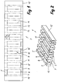
- Figures 1 and 2 show the structure of a packaging insert 1, which consists of an elongated strip of material 3 Cardboard, plastic or from a laminate is formed. At the illustrated embodiment has the packaging insert over a total of five compartments 4, each through Spaces 5 are separated from each other. Is completed the material strip through an end wall 12 or 12 ', which is loose in the box on the side wall of the box is present.
- the dash-dotted lines in FIG. 1 represent fold edges 13 represents, while on the solid lines 14 and 15 of the material strips is separated by an incision.
- the Folded edges and incisions divide the flat material strip when erecting in the configuration according to Figure 2 in individual wall sections.
- Each storage compartment 4 is laterally a total of one Side wall 6 and 6 'limited.
- the side walls are below connected by a bottom 9.
- the gaps 5 form the actual waves with the wave crests or Top sides 11.
- Each side wall 6 or 6 ' is divided into the two end sections 7 and 7 'and the intermediate Middle section 8.
- the middle sections 8 are in the present embodiment angled outwards, which is particularly evident from FIG. 4.
- Each middle section 8 is defined by a folded edge 13 or divided by cuts 14 into two surfaces 16, 16 ', which converge at an obtuse angle ⁇ . Without that pre-marked division into two areas would be the Bend the middle section 8 in an arc. Obviously the cross-section of the Enlarged compartments, in the present case by forming an approximately hexagonal cross section.
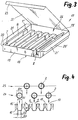
- Figure 3 shows the arrangement of the packaging insert 1 according to Figure 2 in a box 17 made from a single blank can be made of the same material as the packaging insert.
- the deposit will be advantageous immediately during the manufacture of the box with the box bottom 18 glued.
- the box has the two Long side walls 19 and 19 ', the two transverse side walls 20 and 20 'and via a hinged hinged lid 22, which with an insertion tongue 23 is provided.
- the packaging interior is on the side protected by the dust flaps 21 and 21 '.
- the filling process is also shown schematically in FIG shown.
- the individual ampoules 2 are each simultaneously in a first layer 24 and in a second layer 25 inserted.
- the first row 24 is from the left seen to the right, the first, the third and the fifth Storage compartment filled.
- the wave crests 11 can each in the direction of the arrow x towards the empty receiving compartment dodge.
- the second layer 25 is then inserted, the second and fourth compartments are also filled become. Again, the wave crests can dodge the already filled compartments.
- a simultaneous it is not possible to insert them in all of the compartments possible because the width B4 of an ampoule is larger than the width B1 of the receiving openings.
Abstract
Description
Die Erfindung betrifft ein Verpackungsmittel für längliche
Gegenstände, insbesondere für Ampullen, gemäss dem Oberbegriff
vom Anspruch 1. Die in der Regel sehr bruchempfindlichen
Gegenstände müssen beispielsweise in einer Schachtel
einzeln gelagert werden und dürfen sich gegenseitig nicht
berühren. Der Einsatz wellenartig gefalteter Materialstreifen
ist daher für derartige Zwecke seit langem bekannt und gebräuchlich.The invention relates to a packaging means for elongated
Objects, in particular for ampoules, according to the generic term
from
Um Ampullen nicht nur seitlich voneinander abzugrenzen, sondern diese auch bezüglich ihrer radialen Lage festzuhalten, ist es bereits bekannt, die Aufnahmefächer im Querschnitt als nach oben geöffnete Waben auszubilden. Derartige, in eine Schachtel integrierte Verpackungsmittel sind beispielsweise in der FR-A 1 049 050 oder in der CH-A 263 453 beschrieben. Der Vorteil der nach oben geöffneten Waben besteht darin, dass die Ampullen von oben eingelegt werden können und dass die einzelnen Ampullen klemmend erfasst werden. Ein Nachteil dieser bekannten Verpackungsmittel besteht allerdings darin, dass die Ampullen in Axialrichtung nicht abgestützt sind. Bei Schlägen und Stössen sind daher gerade die empfindlichen Ampullenspiesse hohen Belastungen ausgesetzt, was oft zu einem Ampullenbruch führt.In order not only to separate ampoules from the side, but also to record them with regard to their radial position, it is already known, the receiving compartments in cross section as honeycombs open upwards. Such, packaging materials integrated in a box are, for example in FR-A 1 049 050 or in CH-A 263 453 described. The advantage of the open honeycomb is that the ampoules are inserted from above and that the individual ampoules are clamped. A disadvantage of this known packaging means however, in that the ampoules are not in the axial direction are supported. For blows and bumps are therefore straight the sensitive ampoule skewers are exposed to high loads, which often leads to an ampoule break.
Es ist daher eine Aufgabe der Erfindung, ein Verpackungsmittel
der eingangs genannten Art zu schaffen, mit dessen
Hilfe insbesondere Ampullen nicht nur radial, sondern auch
axial abgestützt werden können. Das Verpackungsmittel soll
ausserdem einfach in der Herstellung sein und sich für den
Einsatz in automatischen Verpackungslinien gut eignen. Diese
Aufgabe wird erfindungsgemäss mit einem Verpackungsmittel
gelöst, dass die Merkmale des Anspruchs 1 aufweist.It is therefore an object of the invention to provide packaging
to create of the type mentioned, with its
Aid in particular ampoules not only radially but also
can be supported axially. The packaging material should
also easy to manufacture and for the
Well suited for use in automatic packaging lines. This
According to the invention, the object is achieved with a packaging material
solved that has the features of
Durch die Unterteilung der Seitenwände der Aufnahmefächer oder ggf. auch nur einer der Seitenwände in zwei endseitige Abschnitte und einen von diesen abgesetzten Mittelabschnitt, wird in Axialrichtung je eine Stützschulter geschaffen, an der sich der Gegenstand abstützen kann. Der Mittelabschnitt kann dabei gekrümmt oder abgewinkelt verlaufen. In beiden Fällen lässt sich eine klemmende, zangenartige Erfassung der Gegenstände erreichen. Vorzugsweise sind beide Seitenwände eines Aufnahmefachs symmetrisch mit einem derartigen Mittelabschnitt ausgebildet, doch würde es zur axialstabilen Lagerung auch genügen, nur an einer Seitenwand einen Mittelabschnitt vorzusehen.By dividing the side walls of the compartments or possibly only one of the side walls in two end sides Sections and a central section separated from them, a support shoulder is created in the axial direction that the object can support. The middle section can be curved or angled. In both Cases can be a pinching, pincer-like detection of the Reach objects. Both side walls are preferred a receiving compartment symmetrically with such a central section trained, but it would be axially stable storage also sufficient, a central section only on one side wall to provide.
Eine Stützschulter von ausreichender Tiefe lässt sich besonders gut dadurch erzielen, dass das Aufnahmefach zwischen den beiden Seitenwänden einen Boden aufweist, dessen Breite im Bereich des Mittelabschnitts kleiner ist, als die Breite im Bereich der endseitigen Abschnitte. Im Extremfall könnten die Mittelabschnitte im Bereich des Bodens praktisch zusammenlaufen.A support shoulder of sufficient depth is particularly easy achieve well by the fact that the compartment between the both side walls has a bottom, the width of the Area of the middle section is smaller than the width in Area of the end sections. In extreme cases, they could Middle sections practically converge in the area of the floor.
Im oberen Bereich kann das Aufnahmefach zwischen den beiden Seitenwänden in der Ebene der Wellenkämme eine Einfüllöffnung aufweisen, deren Breite im Bereich der Mittelabschnitte grösser ist als die Breite im Bereich der endseitigen Abschnitte. Diese Massnahme trägt dazu bei, das Einschieben der Gegenstände von oben etwas zu erleichtern, so dass kein zu grosser Widerstand überwunden werden muss. Die Breite der Einfüllöffnung könnte aber auch gleich sein, wie die Breite zwischen den beiden endseitigen Abschnitten.In the upper area, the storage compartment can be between the two Side walls in the plane of the wave crests a fill opening have, whose width in the region of the central sections is greater than the width in the area of the end sections. This measure helps to insert the To lighten objects from above somewhat, so no too great resistance must be overcome. The width of the The filling opening could also be the same as the width between the two end sections.
Insbesondere für die Lagerung zylindrischer Gegenstände, wie z.B. Glasampullen, ist es besonders vorteilhaft, wenn die Mittelabschnitte durch eine Falzkante in zwei in einem stumpfen Winkel zueinander geneigte Flächen unterteilt sind, wobei im Bereich der Mittelabschnitte das Aufnahmefach einen etwa sechseckigen Querschnitt aufweist. Die Ampulle wird auf diese Weise linienförmig an vier Stellen festgehalten. Falls der längliche Gegenstand selbst einen polygonalen Querschnitt aufweist, könnte es aber auch zweckmässig sein, den Mittelabschnitt als gekrümmte Wandpartie auszubilden, so dass in jedem Fall der längliche Gegenstand nur linienförmig anliegt.Especially for the storage of cylindrical objects, such as e.g. Glass ampoules, it is particularly advantageous if the Middle sections through a folded edge in two in one blunt Surfaces inclined at an angle to each other are divided, whereby in the area of the middle sections the receiving compartment approximately has hexagonal cross section. The ampoule is on this Holds in a line at four points. If the elongated object itself a polygonal cross section has, it could also be appropriate, the middle section to be designed as a curved wall section, so that in in any case, the elongated object is only in line.
Die endseitigen Abschnitte sind vorteilhaft durch einen
Einschnitt vom Mittelabschnitt abgesetzt. In bestimmten
Fällen könnte aber zwischen dem Mittelabschnitt und den
endseitigen Abschnitten auch ein Zwischenraum vorgesehen
werden. Eine einfache und zweckmässige Herstellung wird
dadurch erreicht, dass der Materialstreifen im Bereich der
endseitigen Abschnitte winklig, z.B. rechtwinklig mäanderförmig
verläuft. Die erfindungsgemässen Vorteile könnten aber
auch mit einem beispielsweise sinusförmigen Materialstreifen
erzielt werden.
Das Verpackungsmittel kann unmittelbar mit einem Wandabschnitt
einer Schachtel, beispielsweise mit dem Bodenabschnitt
verbunden werden. Es ist aber auch denkbar, das
Verpackungsmittel als separate Verpackungseinlage auszubilden,
die nachträglich in eine Schachtel eingelegt wird. In
einem derartigen Fall würde der wellenartig gefaltete Materialstreifen
mit einem Trägerabschnitt stabilisiert.The end sections are advantageously offset from the central section by an incision. In certain cases, however, an intermediate space could also be provided between the central section and the end sections. A simple and expedient production is achieved in that the material strip extends in an angular manner in the area of the end sections, for example at right angles in a meandering manner. The advantages according to the invention could also be achieved, for example, with a sinusoidal strip of material.
The packaging means can be connected directly to a wall section of a box, for example to the bottom section. However, it is also conceivable to design the packaging means as a separate packaging insert which is subsequently placed in a box. In such a case, the wavy material strip would be stabilized with a carrier section.
Die Erfindung betrifft auch ein Verfahren zum Füllen eines
erfindungsgemässen Verpackungsmittels, das durch die Merkmale
im Anspruch 9 gekennzeichnet ist. Durch das Einlegen in zwei
Lagen können die einzelnen Wellenkämme jeweils immer in
Richtung gegen das benachbarte Aufnahmefach ausweichen, in
welches gerade kein Gegenstand eingelegt wird. Selbstverständlich
wäre es in bestimmten Fällen aber auch denkbar, die
Gegenstände sequentiell in die Aufnahmefächer einzulegen.The invention also relates to a method for filling a
Packaging means according to the invention by the features
is characterized in
Ein Ausführungsbeispiel der Erfindung ist in den Zeichnungen dargestellt und wird nachstehend genauer beschrieben. Es zeigen:
Figur 1- eine Draufsicht auf einen Materialstreifen vor der wellenartigen Deformation,
Figur 2- eine perspektivische Darstellung des Materialstreifens gemäss
Figur 1 nach der wellenartigen Deformation, Figur 3- das Verpackungsmittel gemäss
Figur 2 in einer Schachtel, und Figur 4- eine schematische Darstellung des Verpackungsmittels
gemäss
Figur 2 vor dem Einlegen der Gegenstände.
- Figure 1
- a plan view of a strip of material before the wave-like deformation,
- Figure 2
- 2 shows a perspective illustration of the material strip according to FIG. 1 after the wave-like deformation,
- Figure 3
- the packaging according to Figure 2 in a box, and
- Figure 4
- a schematic representation of the packaging according to Figure 2 before inserting the objects.
Die Figuren 1 und 2 zeigen den Aufbau einer Verpackungseinlage
1, die aus einem länglichen Materialstreifen 3 aus
Karton, Kunststoff oder aus einem Laminat gebildet wird. Beim
dargestellten Ausführungsbeispiel verfügt die Verpackungseinlage
über insgesamt fünf Aufnahmefächer 4, die jeweils durch
Zwischenräume 5 voneinander getrennt sind. Abgeschlossen wird
der Materialstreifen durch eine Abschlusswand 12 bzw. 12',
welche in der Schachtel lose an der Seitenwand der Schachtel
anliegt.Figures 1 and 2 show the structure of a
Die strichpunktierten Linien in Figur 1 stellen Falzkanten 13
dar, während an den ausgezogenen Linien 14 und 15 der Materialstreifen
durch einen Einschnitt durchgetrennt ist. Die
Falzkanten und Einschnitte unterteilen den flächigen Materialstreifen
beim Aufrichten in die Konfiguration gemäss
Figur 2 in einzelne Wandpartien.The dash-dotted lines in FIG. 1 represent
Jedes Aufnahmefach 4 wird seitlich insgesamt durch je eine
Seitenwand 6 und 6' begrenzt. Die Seitenwände sind unten
durch einen Boden 9 miteinander verbunden. Die Zwischenräume
5 bilden die eigentlichen Wellen mit den Wellenkämmen bzw.
Oberseiten 11. Je eine Seitenwand 6 bzw. 6' ist unterteilt in
die beiden endseitigen Abschnitte 7 und 7' und den dazwischenliegenden
Mittelabschnitt 8. Die Mittelabschnitte 8 sind
im vorliegenden Ausführungsbeispiel nach aussen hin abgewinkelt,
was insbesondere aus Figur 4 ersichtlich ist.Each
Jeder Mittelabschnitt 8 ist durch eine Falzkante 13 bzw.
durch Einschnitte 14 in zwei Flächen 16, 16' unterteilt,
welche in einem stumpfen Winkel α zusammenlaufen. Ohne die
vormarkierte Unterteilung in zwei Flächen würde sich der
Mittelabschnitt 8 bogenförmig krümmen. Ersichtlicherweise
wird im Bereich der Mittelabschnitte der Querschnitt der
Aufnahmefächer vergrössert, und zwar im vorliegenden Fall
durch die Bildung eines etwa sechseckigen Querschnitts.Each
Damit sich beim Aufrichten des Materialstreifens 3 die Mittelabschnitte
8 relativ zu den endseitigen Abschnitten 7 und
7' überhaupt nach aussen deformieren, müssen die Mittelabschnitte
ersichtlicherweise relativ zur Höhe der endseitigen
Abschnitte eine Ueberlänge aufweisen. Diese Ueberlänge wird
durch die Länge der Trennschnitte 15 definiert, welche die
Mittelabschnitte 8 von den endseitigen Abschnitten 7, 7'
unterteilen. Wie aus Figur 1 ersichtlich ist, erhalten derart
die Mittelabschnitte die Länge L1 und die endseitigen Abschnitte
L2. Gemäss Figur 4 ergibt dies im aufgerichteten
Zustand eine Breite B1 der Aufnahmeöffnungen 10, welche im
Bereich der Mittelabschnitte grösser ist, als die Breite B3
in der gleichen Ebene im Bereich der endseitigen Abschnitte 7
und 7'. Am Boden 9 sind die Breitenverhältnisse gerade umgekehrt.
Dort ist die Breite B2 im Bereich der Mittelabschnitte
kleiner als die Breite B3 im Bereich der endseitigen Abschnitte.So that the middle sections when the
Figur 3 zeigt die Anordnung der Verpackungseinlage 1 gemäss
Figur 2 in einer Schachtel 17, die aus einem einzigen Zuschnitt
aus dem gleichen Material gefertigt sein kann, wie
die Verpackungseinlage. Die Einlage wird dabei vorteilhaft
unmittelbar bei der Herstellung der Schachtel mit dem Schachtelboden
18 verklebt. Die Schachtel verfügt über die beiden
Längsseitenwände 19 und 19', die beiden Querseitenwände 20
und 20' und über einen angelenkten Klappdeckel 22, der mit
einer Einsteckzunge 23 versehen ist. Seitlich wird der Verpackungsinnenraum
durch die Staublaschen 21 und 21' geschützt.Figure 3 shows the arrangement of the
In der Darstellung gemäss Figur 3 ist nur eine einzige
Spiessampulle 2 eingelegt. Die Verpackungseinlage 1 schliesst
sich unmittelbar an die Längsseitenwand 19 an, ist jedoch
weniger breit als die Gesamtbreite der Schachtel, so dass
ein Freiraum 26 für die Ampullenspiesse verbleibt. Der zylindrische
Abschnitt für die Ampulle stützt sich jeweils an
einer Seitenkante der endseitigen Abschnitte 7 und 7' ab.In the illustration according to FIG. 3 there is only one
In Figur 4 ist ausserdem noch schematisch der Füllvorgang
dargestellt. Die einzelnen Ampullen 2 werden jeweils gleichzeitig
in einer ersten Lage 24 und in einer zweiten Lage 25
eingelegt. Beim Einlegen der ersten Reihe 24 wird von links
nach rechts gesehen, das erste, das dritte und das fünfte
Aufnahmefach gefüllt. Die Wellenkämme 11 können dabei jeweils
in Pfeilrichtung x gegen das leerbleibende Aufnahmefach hin
ausweichen. Anschliessend wird die zweite Lage 25 eingelegt,
wobei auch noch das zweite und das vierte Aufnahmefach gefüllt
werden. Auch dabei können die Wellenkämme wiederum
gegen die bereits gefüllten Fächer hin ausweichen. Ein simultanes
Einlegen in sämtliche Aufnahmefächer ist dagegen nicht
möglich, weil die Breite B4 einer Ampulle grösser ist, als
die Breite B1 der Aufnahmeöffnungen. Dieser scheinbare Nachteil
bezogen auf den Abfüllvorgang ist jedoch gleichzeitig
ein erheblicher Vorteil für die Sicherung der Ampullen in
ihren Aufnahmefächern. Fällt nämlich beispielsweise die
Schachtel 17 auf ihren Deckel 22, bewegen sich alle Ampullen
gleichzeitig gegen die Einfüllöffnungen 10 hin. Dabei sperren
sie sich jedoch gegenseitig, so dass ein Ausweichen der
Wellenkämme 11 in Pfeilrichtung x wie beim Einfüllen nicht
möglich ist.The filling process is also shown schematically in FIG
shown. The
Claims (9)
- A packaging means (1) for elongate objects, in particular for ampullas (2), consisting of a material strip (3) which is folded in a wave-like manner such that in each case there are formed parallel receiving compartments (4) for the objects which are arranged at a distance to one another, characterised in that the receiving compartments (4) at least partly comprise at least one lateral wall (6) with a middle section (8) which is between two end side sections (7, 7') and is set back from these and which with respect to the end side sections (7, 7'), increasing the cross section of the receiving compartment in this region, runs in an arcuate or bent manner.
- A packaging means according to claim 1, characterised in that both lateral walls (6, 6') of a receiving compartment (4) are formed symmetrically to a middle section (8).
- A packaging means according to claim 2, characterised in that the receiving compartment between the two lateral walls (6, 6') comprises a floor (9) whose width (B2) in the region of the middle section (8) is smaller than the width (B3) in the region of the end-side sections (7, 7').
- A packaging means according to claim 2 or 3, characterised in that the receiving compartment (4) between the two lateral walls (6, 6') in the plane of the wave crests (11) comprises a filling opening (10) whose width in the region of the middle section (8) is smaller than the width (B3) in the region of the end-side sections (7, 7').
- A packaging means according to one of claims 2 to 4, characterised in that the middle sections (8) is subdivided by a longitudinal folding line (13) into two surfaces (16, 16') inclined at an obtuse angle (α) to one another, wherein in the region of the middle sections the receiving compartment (4) comprises a roughly hexagonal cross section.
- A packaging means according to one of the claims 1 to 5, characterised in that the end-side sections (7, 7') are set back from the middle section (8) by an incision (15).
- A packaging means according to one of the claims 1 to 6, characterised in that the material strip in the region of the end-side sections (7, 7') runs at right angles in a meander-shaped manner.
- A box (17) with a packaging means (1) according to one of the claims 1 to 7, characterised in that the packaging means on the floor sections (9) of the receiving compartments (4) is connected to a wall section, in particular to the floor section (18) of the box.
- A method for filling a packaging means according to one of the claims 1 to 7 with elongate objects, whose width (B4) is larger than the width (B1) between the wave crests (11) in the region of the middle sections (8), characterised in that firstly a first layer (24) of elongate objects (2) are placed simultaneously from above into the receiving compartments (4), wherein next to each object at least one receiving compartment remains empty, and that subsequently a second layer (25) of elongate objects is placed simultaneously from above into the empty receiving compartments, wherein in each case the wave crests (11) of the receiving compartments, on placing in the first and second layer, open elastically and after the placing in, again return into their original position.
Applications Claiming Priority (2)
| Application Number | Priority Date | Filing Date | Title |
|---|---|---|---|
| CH300195 | 1995-10-24 | ||
| CH3001/95 | 1995-10-24 |
Publications (2)
| Publication Number | Publication Date |
|---|---|
| EP0770554A1 EP0770554A1 (en) | 1997-05-02 |
| EP0770554B1 true EP0770554B1 (en) | 1999-06-02 |
Family
ID=4246408
Family Applications (1)
| Application Number | Title | Priority Date | Filing Date |
|---|---|---|---|
| EP96810510A Expired - Lifetime EP0770554B1 (en) | 1995-10-24 | 1996-07-30 | Package for elongated articles and method for its filling |
Country Status (3)
| Country | Link |
|---|---|
| EP (1) | EP0770554B1 (en) |
| AT (1) | ATE180734T1 (en) |
| DE (1) | DE59602075D1 (en) |
Cited By (1)
| Publication number | Priority date | Publication date | Assignee | Title |
|---|---|---|---|---|
| US10577186B2 (en) | 2011-08-18 | 2020-03-03 | Countlab, Inc. | Container filling machine |
Families Citing this family (5)
| Publication number | Priority date | Publication date | Assignee | Title |
|---|---|---|---|---|
| EP0881154A1 (en) * | 1997-05-30 | 1998-12-02 | GRAFICHE EIKON S.r.l. | Vial container |
| FR2878232B1 (en) * | 2004-11-19 | 2007-02-23 | Finega Sa | PROTECTION STRUCTURE FOR A PRODUCT AND FLAN PREDECOUPE FOR OBTAINING SUCH A STRUCTURE |
| WO2008098340A1 (en) | 2007-02-16 | 2008-08-21 | Countlab Inc. | A container filling machine |
| US8006468B2 (en) | 2008-04-14 | 2011-08-30 | Countlab Inc. | Container filling machine having vibration trays |
| CA2686751C (en) | 2008-12-02 | 2017-02-21 | Countlab, Inc. | A discrete article spacing apparatus for vibration trays |
Family Cites Families (5)
| Publication number | Priority date | Publication date | Assignee | Title |
|---|---|---|---|---|
| BE518625A (en) * | ||||
| CH263453A (en) * | 1948-02-02 | 1949-08-31 | Cafag Cartonnagenfabrik Freibu | Ampoule packaging. |
| FR1049050A (en) * | 1952-01-11 | 1953-12-28 | Packaging | |
| IT1238242B (en) * | 1990-02-09 | 1993-07-12 | Maurizio Marchesini | PERFECTED CONTAINER FOR TUBULAR PRODUCTS, SUCH AS GLASS VIALS, BOTTLES AND SIMILAR. |
| DE59200480D1 (en) * | 1991-02-15 | 1994-10-20 | Dividella Ag | Packaging part for holding elongated objects. |
-
1996
- 1996-07-30 AT AT96810510T patent/ATE180734T1/en not_active IP Right Cessation
- 1996-07-30 DE DE59602075T patent/DE59602075D1/en not_active Expired - Fee Related
- 1996-07-30 EP EP96810510A patent/EP0770554B1/en not_active Expired - Lifetime
Cited By (1)
| Publication number | Priority date | Publication date | Assignee | Title |
|---|---|---|---|---|
| US10577186B2 (en) | 2011-08-18 | 2020-03-03 | Countlab, Inc. | Container filling machine |
Also Published As
| Publication number | Publication date |
|---|---|
| EP0770554A1 (en) | 1997-05-02 |
| DE59602075D1 (en) | 1999-07-08 |
| ATE180734T1 (en) | 1999-06-15 |
Similar Documents
| Publication | Publication Date | Title |
|---|---|---|
| EP0362581B1 (en) | Packaging made from cardboard or the like | |
| DD299167A5 (en) | PORT FOR RECEIVING ROUND KOERPER | |
| DE4003104C2 (en) | Packaging container for holding objects, in particular chocolate articles, and blanks for forming the same | |
| EP2028115B1 (en) | Presentation container, blank and method for its manufacture | |
| DE2236426C3 (en) | Shaped box for holding fragile goods | |
| EP0770554B1 (en) | Package for elongated articles and method for its filling | |
| EP0976660A1 (en) | Package for a group of articles and process for its manufacture | |
| DE9320302U9 (en) | Blank for the production of a box and box from sheet material | |
| DE4017399A1 (en) | Carton for small articles - has insert with dividing walls formed by folds in square blank with square holes | |
| CH669768A5 (en) | ||
| DE3616632C2 (en) | ||
| DE19530156C2 (en) | egg carton | |
| DE69831630T2 (en) | Packaging for cigarette packs | |
| WO1986005159A1 (en) | Crate | |
| DE3741283C2 (en) | ||
| EP0857656B1 (en) | Device, especially for transport and presentation of an article | |
| DE3310596A1 (en) | Folding box with separating device | |
| EP0786413A1 (en) | Container | |
| DE202006014891U1 (en) | Cardboard blank for producing holder for pharmaceutical ampoules in cartons has sections with scores on either side and Z-shaped slit through its center, allowing them to fold upwards, forming tabs which hold ampoule in position | |
| DE3939948C1 (en) | ||
| DE2537881B2 (en) | Compartment for inserting into packs for the division of objects such as bottles, cans, etc. | |
| DE616975C (en) | ||
| DE2403883A1 (en) | HOLDER AND PACKAGING, ESPECIALLY FOR MULTIPLE ITEMS | |
| DD279658A5 (en) | FLAECHENVERRIEGELUNGSVORRICHTUNG | |
| WO2001040061A1 (en) | Partitioning insert and packaging unit produced by using the same |
Legal Events
| Date | Code | Title | Description |
|---|---|---|---|
| PUAI | Public reference made under article 153(3) epc to a published international application that has entered the european phase |
Free format text: ORIGINAL CODE: 0009012 |
|
| AK | Designated contracting states |
Kind code of ref document: A1 Designated state(s): AT BE CH DE DK ES FI FR GB GR IE IT LI NL PT SE |
|
| 17P | Request for examination filed |
Effective date: 19970620 |
|
| GRAG | Despatch of communication of intention to grant |
Free format text: ORIGINAL CODE: EPIDOS AGRA |
|
| GRAG | Despatch of communication of intention to grant |
Free format text: ORIGINAL CODE: EPIDOS AGRA |
|
| GRAH | Despatch of communication of intention to grant a patent |
Free format text: ORIGINAL CODE: EPIDOS IGRA |
|
| 17Q | First examination report despatched |
Effective date: 19981012 |
|
| GRAH | Despatch of communication of intention to grant a patent |
Free format text: ORIGINAL CODE: EPIDOS IGRA |
|
| GRAA | (expected) grant |
Free format text: ORIGINAL CODE: 0009210 |
|
| AK | Designated contracting states |
Kind code of ref document: B1 Designated state(s): AT BE CH DE DK ES FI FR GB GR IE IT LI NL PT SE |
|
| PG25 | Lapsed in a contracting state [announced via postgrant information from national office to epo] |
Ref country code: SE Free format text: THE PATENT HAS BEEN ANNULLED BY A DECISION OF A NATIONAL AUTHORITY Effective date: 19990602 Ref country code: NL Free format text: LAPSE BECAUSE OF FAILURE TO SUBMIT A TRANSLATION OF THE DESCRIPTION OR TO PAY THE FEE WITHIN THE PRESCRIBED TIME-LIMIT Effective date: 19990602 Ref country code: GR Free format text: LAPSE BECAUSE OF NON-PAYMENT OF DUE FEES Effective date: 19990602 Ref country code: GB Free format text: LAPSE BECAUSE OF FAILURE TO SUBMIT A TRANSLATION OF THE DESCRIPTION OR TO PAY THE FEE WITHIN THE PRESCRIBED TIME-LIMIT Effective date: 19990602 Ref country code: FR Free format text: LAPSE BECAUSE OF FAILURE TO SUBMIT A TRANSLATION OF THE DESCRIPTION OR TO PAY THE FEE WITHIN THE PRESCRIBED TIME-LIMIT Effective date: 19990602 Ref country code: FI Free format text: LAPSE BECAUSE OF NON-PAYMENT OF DUE FEES Effective date: 19990602 Ref country code: ES Free format text: THE PATENT HAS BEEN ANNULLED BY A DECISION OF A NATIONAL AUTHORITY Effective date: 19990602 |
|
| REF | Corresponds to: |
Ref document number: 180734 Country of ref document: AT Date of ref document: 19990615 Kind code of ref document: T |
|
| REG | Reference to a national code |
Ref country code: CH Ref legal event code: EP |
|
| REF | Corresponds to: |
Ref document number: 59602075 Country of ref document: DE Date of ref document: 19990708 |
|
| PGFP | Annual fee paid to national office [announced via postgrant information from national office to epo] |
Ref country code: BE Payment date: 19990715 Year of fee payment: 4 |
|
| REG | Reference to a national code |
Ref country code: IE Ref legal event code: FG4D Free format text: GERMAN |
|
| PGFP | Annual fee paid to national office [announced via postgrant information from national office to epo] |
Ref country code: DE Payment date: 19990729 Year of fee payment: 4 |
|
| PG25 | Lapsed in a contracting state [announced via postgrant information from national office to epo] |
Ref country code: AT Free format text: LAPSE BECAUSE OF NON-PAYMENT OF DUE FEES Effective date: 19990730 |
|
| PG25 | Lapsed in a contracting state [announced via postgrant information from national office to epo] |
Ref country code: IE Free format text: LAPSE BECAUSE OF NON-PAYMENT OF DUE FEES Effective date: 19990802 |
|
| PG25 | Lapsed in a contracting state [announced via postgrant information from national office to epo] |
Ref country code: PT Free format text: LAPSE BECAUSE OF FAILURE TO SUBMIT A TRANSLATION OF THE DESCRIPTION OR TO PAY THE FEE WITHIN THE PRESCRIBED TIME-LIMIT Effective date: 19990902 Ref country code: DK Free format text: LAPSE BECAUSE OF FAILURE TO SUBMIT A TRANSLATION OF THE DESCRIPTION OR TO PAY THE FEE WITHIN THE PRESCRIBED TIME-LIMIT Effective date: 19990902 |
|
| EN | Fr: translation not filed | ||
| GBV | Gb: ep patent (uk) treated as always having been void in accordance with gb section 77(7)/1977 [no translation filed] |
Effective date: 19990602 |
|
| PLBE | No opposition filed within time limit |
Free format text: ORIGINAL CODE: 0009261 |
|
| STAA | Information on the status of an ep patent application or granted ep patent |
Free format text: STATUS: NO OPPOSITION FILED WITHIN TIME LIMIT |
|
| REG | Reference to a national code |
Ref country code: IE Ref legal event code: MM4A |
|
| 26N | No opposition filed | ||
| PG25 | Lapsed in a contracting state [announced via postgrant information from national office to epo] |
Ref country code: LI Free format text: LAPSE BECAUSE OF NON-PAYMENT OF DUE FEES Effective date: 20000731 Ref country code: CH Free format text: LAPSE BECAUSE OF NON-PAYMENT OF DUE FEES Effective date: 20000731 Ref country code: BE Free format text: LAPSE BECAUSE OF NON-PAYMENT OF DUE FEES Effective date: 20000731 |
|
| BERE | Be: lapsed |
Owner name: DIVIDELLA A.G. Effective date: 20000731 |
|
| REG | Reference to a national code |
Ref country code: CH Ref legal event code: PL |
|
| PG25 | Lapsed in a contracting state [announced via postgrant information from national office to epo] |
Ref country code: DE Free format text: LAPSE BECAUSE OF NON-PAYMENT OF DUE FEES Effective date: 20010501 |
|
| PG25 | Lapsed in a contracting state [announced via postgrant information from national office to epo] |
Ref country code: IT Free format text: LAPSE BECAUSE OF NON-PAYMENT OF DUE FEES;WARNING: LAPSES OF ITALIAN PATENTS WITH EFFECTIVE DATE BEFORE 2007 MAY HAVE OCCURRED AT ANY TIME BEFORE 2007. THE CORRECT EFFECTIVE DATE MAY BE DIFFERENT FROM THE ONE RECORDED. Effective date: 20050730 |