EP0770552B1 - Bottle crates and method for manufacturing such crates - Google Patents
Bottle crates and method for manufacturing such crates Download PDFInfo
- Publication number
- EP0770552B1 EP0770552B1 EP95116856A EP95116856A EP0770552B1 EP 0770552 B1 EP0770552 B1 EP 0770552B1 EP 95116856 A EP95116856 A EP 95116856A EP 95116856 A EP95116856 A EP 95116856A EP 0770552 B1 EP0770552 B1 EP 0770552B1
- Authority
- EP
- European Patent Office
- Prior art keywords
- handle
- crate
- plastic
- bead
- shaped
- Prior art date
- Legal status (The legal status is an assumption and is not a legal conclusion. Google has not performed a legal analysis and makes no representation as to the accuracy of the status listed.)
- Expired - Lifetime
Links
Images
Classifications
-
- B—PERFORMING OPERATIONS; TRANSPORTING
- B65—CONVEYING; PACKING; STORING; HANDLING THIN OR FILAMENTARY MATERIAL
- B65D—CONTAINERS FOR STORAGE OR TRANSPORT OF ARTICLES OR MATERIALS, e.g. BAGS, BARRELS, BOTTLES, BOXES, CANS, CARTONS, CRATES, DRUMS, JARS, TANKS, HOPPERS, FORWARDING CONTAINERS; ACCESSORIES, CLOSURES, OR FITTINGS THEREFOR; PACKAGING ELEMENTS; PACKAGES
- B65D25/00—Details of other kinds or types of rigid or semi-rigid containers
- B65D25/28—Handles
- B65D25/30—Hand holes
-
- B—PERFORMING OPERATIONS; TRANSPORTING
- B29—WORKING OF PLASTICS; WORKING OF SUBSTANCES IN A PLASTIC STATE IN GENERAL
- B29C—SHAPING OR JOINING OF PLASTICS; SHAPING OF MATERIAL IN A PLASTIC STATE, NOT OTHERWISE PROVIDED FOR; AFTER-TREATMENT OF THE SHAPED PRODUCTS, e.g. REPAIRING
- B29C45/00—Injection moulding, i.e. forcing the required volume of moulding material through a nozzle into a closed mould; Apparatus therefor
- B29C45/17—Component parts, details or accessories; Auxiliary operations
- B29C45/1703—Introducing an auxiliary fluid into the mould
- B29C45/1704—Introducing an auxiliary fluid into the mould the fluid being introduced into the interior of the injected material which is still in a molten state, e.g. for producing hollow articles
-
- B—PERFORMING OPERATIONS; TRANSPORTING
- B65—CONVEYING; PACKING; STORING; HANDLING THIN OR FILAMENTARY MATERIAL
- B65D—CONTAINERS FOR STORAGE OR TRANSPORT OF ARTICLES OR MATERIALS, e.g. BAGS, BARRELS, BOTTLES, BOXES, CANS, CARTONS, CRATES, DRUMS, JARS, TANKS, HOPPERS, FORWARDING CONTAINERS; ACCESSORIES, CLOSURES, OR FITTINGS THEREFOR; PACKAGING ELEMENTS; PACKAGES
- B65D1/00—Rigid or semi-rigid containers having bodies formed in one piece, e.g. by casting metallic material, by moulding plastics, by blowing vitreous material, by throwing ceramic material, by moulding pulped fibrous material or by deep-drawing operations performed on sheet material
- B65D1/22—Boxes or like containers with side walls of substantial depth for enclosing contents
- B65D1/24—Boxes or like containers with side walls of substantial depth for enclosing contents with moulded compartments or partitions
- B65D1/243—Crates for bottles or like containers
-
- B—PERFORMING OPERATIONS; TRANSPORTING
- B29—WORKING OF PLASTICS; WORKING OF SUBSTANCES IN A PLASTIC STATE IN GENERAL
- B29L—INDEXING SCHEME ASSOCIATED WITH SUBCLASS B29C, RELATING TO PARTICULAR ARTICLES
- B29L2031/00—Other particular articles
- B29L2031/712—Containers; Packaging elements or accessories, Packages
- B29L2031/7134—Crates, e.g. for bottles
-
- B—PERFORMING OPERATIONS; TRANSPORTING
- B65—CONVEYING; PACKING; STORING; HANDLING THIN OR FILAMENTARY MATERIAL
- B65D—CONTAINERS FOR STORAGE OR TRANSPORT OF ARTICLES OR MATERIALS, e.g. BAGS, BARRELS, BOTTLES, BOXES, CANS, CARTONS, CRATES, DRUMS, JARS, TANKS, HOPPERS, FORWARDING CONTAINERS; ACCESSORIES, CLOSURES, OR FITTINGS THEREFOR; PACKAGING ELEMENTS; PACKAGES
- B65D2501/00—Containers having bodies formed in one piece
- B65D2501/24—Boxes or like containers with moulded compartments or partitions
- B65D2501/24006—Details relating to bottle crates
- B65D2501/24012—Materials
- B65D2501/24019—Mainly plastics
-
- B—PERFORMING OPERATIONS; TRANSPORTING
- B65—CONVEYING; PACKING; STORING; HANDLING THIN OR FILAMENTARY MATERIAL
- B65D—CONTAINERS FOR STORAGE OR TRANSPORT OF ARTICLES OR MATERIALS, e.g. BAGS, BARRELS, BOTTLES, BOXES, CANS, CARTONS, CRATES, DRUMS, JARS, TANKS, HOPPERS, FORWARDING CONTAINERS; ACCESSORIES, CLOSURES, OR FITTINGS THEREFOR; PACKAGING ELEMENTS; PACKAGES
- B65D2501/00—Containers having bodies formed in one piece
- B65D2501/24—Boxes or like containers with moulded compartments or partitions
- B65D2501/24006—Details relating to bottle crates
- B65D2501/2405—Construction
- B65D2501/24063—Construction of the walls
- B65D2501/2407—Apertured
-
- B—PERFORMING OPERATIONS; TRANSPORTING
- B65—CONVEYING; PACKING; STORING; HANDLING THIN OR FILAMENTARY MATERIAL
- B65D—CONTAINERS FOR STORAGE OR TRANSPORT OF ARTICLES OR MATERIALS, e.g. BAGS, BARRELS, BOTTLES, BOXES, CANS, CARTONS, CRATES, DRUMS, JARS, TANKS, HOPPERS, FORWARDING CONTAINERS; ACCESSORIES, CLOSURES, OR FITTINGS THEREFOR; PACKAGING ELEMENTS; PACKAGES
- B65D2501/00—Containers having bodies formed in one piece
- B65D2501/24—Boxes or like containers with moulded compartments or partitions
- B65D2501/24006—Details relating to bottle crates
- B65D2501/24363—Handles
- B65D2501/24509—Integral handles
- B65D2501/24522—Integral handles provided near to or at the uper edge or rim
-
- B—PERFORMING OPERATIONS; TRANSPORTING
- B65—CONVEYING; PACKING; STORING; HANDLING THIN OR FILAMENTARY MATERIAL
- B65D—CONTAINERS FOR STORAGE OR TRANSPORT OF ARTICLES OR MATERIALS, e.g. BAGS, BARRELS, BOTTLES, BOXES, CANS, CARTONS, CRATES, DRUMS, JARS, TANKS, HOPPERS, FORWARDING CONTAINERS; ACCESSORIES, CLOSURES, OR FITTINGS THEREFOR; PACKAGING ELEMENTS; PACKAGES
- B65D2501/00—Containers having bodies formed in one piece
- B65D2501/24—Boxes or like containers with moulded compartments or partitions
- B65D2501/24006—Details relating to bottle crates
- B65D2501/24363—Handles
- B65D2501/24541—Hand holes
Definitions
- the invention relates to a crate, in particular a bottle crate made of Plastic is injection molded, with a box bottom and few a handle for carrying the box, the handle at least above and below with a bead-shaped in the longitudinal direction of the handle Section is provided, at least one of which at least one is at least part of its longitudinal extent is hollow by gas injection.
- a box is known from DE-U-94 18 484, which is made of plastic in the Spraying process is made and one box bottom and several handles for Bearing the box.
- the handles are with a top and bottom provided bead-shaped portion which are hollow by gas injection.
- the invention is based on the object, a box of mentioned type so that it is also in full and therefore difficult Condition relatively easy to wear.
- the at the upper edge of the Handle provided bead-shaped section on its free underside is wavy.
- An advantageous embodiment of the invention is characterized in that at least the bead-shaped section arranged on the underside of the handle is at least approximately teardrop-shaped in cross section.
- Another advantageous embodiment of the invention is that between the two bead-shaped sections at least one further rib-shaped section is provided.
- the plastic injected from both sides of the handle can easily become loose connect.
- Another advantageous embodiment of the invention is that the lower bead-shaped section of the handle is arched and the handle on its underside has a convex shape.
- Another advantageous embodiment of the invention resides in a box, in particular a bottle crate made of plastic by injection molding and is provided with a handle which consists of at least two one above the other arranged bead-shaped sections is that at least the lower Outside of the lower bulbous section made of a softer Plastic material is made.
- the softer plastic material also injected into the mold and on the inside with the actual plastic material for making the rest of the box is covered.
- the softer material as a separate Component manufactured and retrofitted to the handle.
- the lower outside of the Handle and the rest of the box are made of a related plastic.
- Fig.1 1 is a bottle crate
- the bottom 2 and four of this has upstanding side walls 3, 4, 5 and 6.
- a handle 7 which up to the height of the upper edge of the Sidewalls are enough.
- This handle 7 is undulating on its underside formed, the waveform of the finger assembly on the human hand is adjusted.
- the handle 7 has three sections 8, 9 and 10 lying one above the other on, which are bulge-shaped.
- the upper and lower sections are 8 and 10 each hollow and with a relatively large Outside diameter manufactured. Both sections 8 and 10 have both in their outer shape as well as in the cross-sectional shape of the cavity a teardrop shape.
- the inner bead-shaped section 9 has a somewhat smaller diameter and is massively trained.
- the plastic is used to form this handle 7 from Floor 2 forth at the same time through the vertical bars 11 and 12 in the actual Handle passed, the two plastic streams usually in the middle of the Handgrip meet and unite there. Because of the already The partial cooling of the plastic can no longer occur be optimal, which would result in a weak point of the handle here.
- the three superimposed sections 8, 9 and 10 are each on one side Flow brakes 13, 14 and 15 are provided in the injection mold, which the Reduce the flow rate of the plastic. This will make each one Meeting point 16, 17 and 18 of the two plastic streams from the middle of the Handle moved to the edge area. For the three sections 8, 9 and 10 lie these meeting points at different positions, so that the Handle receives optimal strength despite any weaknesses.
- the three are one above the other bead-shaped sections 8, 9 and 10 by means of two webs 20 and 21 with each other connected.
- the lower bead-shaped section 10 is essentially drop-shaped formed, its lower surface slightly flattened and in the longitudinal direction is wavy.
- the upper section 8 has a similar teardrop shape Shape and is slightly flattened on its upper surface. Both bead-shaped sections 8 and 10 are hollow, this being the case used compressed gas was blown through the opening 19 and from there flows simultaneously into the two sections 8, 10.
- the inner shape of the two Cavities are also teardrop-shaped.
- each of these handles 38 contains three overlapping bead or rib-shaped sections 40, 41 and 42, of which only the lower section 42 is hollow.
- the three bead or rib-shaped Sections 40, 41 and 42 are about webs 43 and 44, which are proportionate have a small cross-section, interconnected.
- the entire handle is supplied with liquid plastic via the two vertical bars 45 and 46, the reaches the three sections 40, 41, 42 and the two webs 43, 44 simultaneously. At the same time, pressure gas flows through the inflow opening 19 into the lower section 42 pressed in, which forms a cavity there.
- section 42 acts the compressed gas as long as its pressure is maintained on the plastic in the other sections 40 and 41 or the webs 43 and 44, but can be there none due to the small cross-sections or the flow brake 47 provided Form cavity.
- the underside of the handle 38 is again wavy educated.
- a handle 50 is shown, the two superimposed bead-shaped Sections 51 and 52. Both sections are teardrop-shaped in cross section formed and connected to each other by a web 53. Inside are those two bead-shaped sections 51, 52 are also drop-shaped, wherein the two cavities were created by separately blowing in compressed gas. The lower of the two sections is both on its underside and on its free Wavy upper side. Also the free underside of the upper section 52 is wave-shaped. As a result, the fingers or fingertips experience in the Wave valleys have a very good lateral hold.
- the lower bead-shaped section is 61 of the handle 60 is hollow and has both outside and inside teardrop shape.
- the upper section 62 is also in cross section drop-shaped; however, cavity formation has not taken place here.
- a layer 63 made of softer Plastic material is provided, which forms the lower end surface. This location 63 is through a separate, not shown injection nozzle in this area injected and after the injection of the actual box. However, it is also possible to make this layer 63 separately and either before spraying the Insert the box into the injection mold or subsequently on the finished box to attach.
- the lower limit of Handle 70 of the box 71 curved. So the lower one runs bead-shaped section 72 arcuate. The upper bead portion 73 and two rib-shaped sections 74 and 75 lying in between run against it straightforward. Here, too, there are webs 76, 77 and 78 between the neighboring ones Sections provided. Through the two inflow openings 19 and 23 through a flow brake 23 are shielded from each other, pressurized gas enters the lower and upper beaded portions 72 and 73, making them be hollow independently of each other. In the two narrow side walls the box 71 can also straight instead of the curved handles 70 trained handles can be provided, such as in Figures 3 and 4 are shown. But it can also be arch-shaped on the underside Handles are used.
Landscapes
- Engineering & Computer Science (AREA)
- Mechanical Engineering (AREA)
- Manufacturing & Machinery (AREA)
- Ceramic Engineering (AREA)
- Details Of Rigid Or Semi-Rigid Containers (AREA)
- Packages (AREA)
Abstract
Description
Die Erfindung bezieht sich auf einen Kasten, insbesondere Flaschenkasten, der aus Kunststoff im Spritzverfahren hergestellt ist, mit einem Kastenboden und wenigsten einem Handgriff zum Tragen des Kastens, wobei der Handgriff wenigstens oben und unten mit einem wulstförmigen in Längsrichtung des Handgriffs verlaufenden Abschnitt versehen ist, von denen wenigstens einer wenigstens einer wenigstens auf einem Teil seiner Längserstreckung durch Gaseinblasung hohl ausgebildet ist.The invention relates to a crate, in particular a bottle crate made of Plastic is injection molded, with a box bottom and few a handle for carrying the box, the handle at least above and below with a bead-shaped in the longitudinal direction of the handle Section is provided, at least one of which at least one is at least part of its longitudinal extent is hollow by gas injection.
Derartige Kästen sind im beladenen Zustand sehr schwer, wobei der Handgriff in die Hand einschneidet und sich damit ein sehr unbequemes Tragen ergibt.Such boxes are very heavy when loaded, with the handle in the Cuts into the hand and is very uncomfortable to carry.
Es sind zahlreiche Versuche bekannt, den Handgriff so auszugestalten, daß er handfreundlicher ist.Numerous attempts are known to design the handle so that it is more hand-friendly.
Beispielweise ist aus DE-U-94 18 484 ein Kasten bekannt, der aus Kunststoff im Spritzverfahren hergestellt ist und der einen Kastenboden und mehrere Handgriffe zum Tragen des Kastens aufweist. Die Handgriffe sind oben und unten mit einem wulstförmigen Abschnitt versehen, die durch Gaseinblasung hohl ausgebildet sind. For example, a box is known from DE-U-94 18 484, which is made of plastic in the Spraying process is made and one box bottom and several handles for Bearing the box. The handles are with a top and bottom provided bead-shaped portion which are hollow by gas injection.
Der Erfindung liegt, hiervon ausgehend die Aufgabe zugrunde, einen Kasten der genannten Art so auszugestalten, daß er sich auch im vollen und damit schweren Zustand verhältnismäßig leicht tragen läßt.The invention is based on the object, a box of mentioned type so that it is also in full and therefore difficult Condition relatively easy to wear.
Diese Aufgabe wird erfindungsgemäß dadurch gelöst, daß der an der unteren Kante des Handgriffs angeordnete wulstförmige Abschnitt sowohl an seiner Unterseite als auch an seiner freien Oberseite wellenförmig ausgebildet ist, wobei die Wellen quer zur Längsrichtung des Handgriffs verlaufen und entsprechend den Fingern der menschlichen Hand ausgebildet sind.This object is achieved in that at the bottom edge arranged on the underside of the handle is also wave-shaped on its free upper side, the waves being transverse to the longitudinal direction of the handle and according to the fingers of the human hand.
Hierdurch wird eine optimale Grifffläche am Handgriff gebildet, welche ein bequemes Tragen auch des vollen Kastens erlaubt. Durch die Gaseinblasung kann im hohl ausgebildeten Bereich Kunststoffmaterial eingespart werden. Darüber hinaus wird aber durch den Gasdruck ein beim Abkühlen des Kunststoffes normalerweise eintretender Schwund ausgeglichen und der fertig abgekühlte Kasten weist keinerlei schwundbedingte Einfallstellen auf. Darüber hinaus wird hiermit eine hohe Stabilität des Handgriffes gewährleistet.This creates an optimal grip area on the handle, which is convenient Carrying of the full box allowed. Due to the gas injection in the hollow trained area plastic material can be saved. Beyond that due to the gas pressure, this normally occurs when the plastic cools down Shrinkage compensated and the completely cooled box shows nothing sink marks due to shrinkage. It also provides high stability of the handle guaranteed.
Erfindungsgemäß kann auch vorgesehen werden, daß der an der oberen Kante des Handgriffs vorgesehene wulstförmige Abschnitt an seiner freien Unterseite wellenförmig ausgebildet ist.According to the invention can also be provided that the at the upper edge of the Handle provided bead-shaped section on its free underside is wavy.
Dadurch erhalten die Fingerspitzen einen sehr guten seitlichen Halt, was das Tragen des Kastens noch wesentlich erleichtert.This gives the fingertips a very good lateral hold, which is what to wear of the box still much relieved.
Eine vorteilhafte Ausgestaltung der Erfindung ist dadurch gekennzeichnet, daß wenigstens der an der Unterseite des Handgriffs angeordnete wulstförmige Abschnitt im Querschnitt wenigstens annähernd tropfenförmig ausgebildet ist.An advantageous embodiment of the invention is characterized in that at least the bead-shaped section arranged on the underside of the handle is at least approximately teardrop-shaped in cross section.
Dadurch wird neben der Handfreundlichkeit eine sehr hohe Festigkeit erzielt. In addition to being easy to use, this results in very high strength.
Eine weitere vorteilhafte Ausgestaltung der Erfindung liegt darin, daß zwischen den beiden wulstförmigen Abschnitten wenigstens ein weiterer rippenförmiger Abschnitt vorgesehen ist.Another advantageous embodiment of the invention is that between the two bead-shaped sections at least one further rib-shaped section is provided.
Damit wird zum einen die Stabilität des Handgriffs noch weiter erhöht und zum anderen der Tragekomfort verbessert, da sich die Fingerspitzen an dem weiteren rippenförmigen Abschnitt abstützen können.On the one hand, this increases the stability of the handle even further, and on the other Others improved the comfort because the fingertips on the other can support rib-shaped section.
Als sehr vorteilhaft hat es sich ergeben, wenn erfindungsgemäß die wulst- und/oder rippenförmigen Abschnitte untereinander verbunden sind.It has been found to be very advantageous if, according to the invention, the beads and / or rib-shaped sections are interconnected.
Dabei kann der von beiden Seiten des Handgriffs eingespritzte Kunststoff sich leicht verbinden.The plastic injected from both sides of the handle can easily become loose connect.
Als sehr vorteilhaft hat es sich auch ergeben, wenn erfindungsgemäß wenigstens der obere und der untere wulstförmige Abschnitt durch voneinander getrennte Gaseinblasung mit einem Hohlraum versehen sind, die keine Verbindung miteinander aufweisen.It has also turned out to be very advantageous if, according to the invention, at least the upper and lower bead-shaped sections separated from each other Gas injection are provided with a cavity that are not connected to each other exhibit.
Damit werden die Vorteile einer hohlen Ausgestaltung der wulstförmigen Abschnitte erzielt ohne die Nachteile bei einer Verbindung der Hohlräume mit deren dann eintretenden unkontrollierten Ausdehnung in Kauf nehmen zu müssen.This gives the advantages of a hollow configuration of the bead-shaped sections achieved without the disadvantages of connecting the cavities to them uncontrolled expansion.
Es hat sich auch als sehr vorteilhaft erwiesen, wenn erfindungsgemäß im Handgriffbereich Fließbremsen für die Kunststoffströme vorgesehen sind, die einerseits die Fließgeschwindigkeit des Kunststoffes reduzieren und andererseits ein Durchbrechen des Gases verhindern.It has also proven to be very advantageous if, according to the invention, in Handle area flow brakes are provided for the plastic flows that reduce the flow rate of the plastic on the one hand and Prevent gas from breaking through.
Damit wird erreicht, daß die Kunststoffströme in den einzelnen wulst- und/oder rippenförmigen Abschnitten unterschiedlich schnell vorankommen, so daß bei beidseitigem Einspritzen des Kunststoffs die Zusammentreff-Stellen der Kunststoffströme an unterschiedlichen Stellen vorliegen. Da die Zusammentreff-Stellen im allgemeinen eine Schwachstelle darstellen, wird hierdurch deren negativer Einfluß auf die Festigkeit des Handgriffs erheblich reduziert. Zum anderen wird an diesen Fließbremsen verhindert, daß sich ungewollte Hohlraumverbindungen einstellen, da bei entsprechender Ausgestaltung der Fließbremsen zwar der Kunststoff durch diese Fließbremsen hindurch gelangt; infolge der sich bildenden Engstelle aber ein Gasdurchtritt nicht erfolgen kann.This ensures that the plastic flows in the individual beads and / or rib-shaped sections progress at different speeds, so that at injecting the plastic on both sides the meeting points of the Plastic flows are present in different places. Because the meeting points generally represent a vulnerability, it will make it more negative Influence on the strength of the handle significantly reduced. The other is on These flow brakes prevent unwanted void connections adjust, because with a corresponding design of the flow brakes the plastic passes through these flow brakes; as a result of the narrowing gas cannot pass through.
Eine weitere vorteilhafte Ausgestaltung der Erfindung liegt darin, daß der untere wulstförmige Abschnitt des Handgriffs bogenförmig verläuft und der Handgriff an seiner Unterseite damit eine konvexe Form aufweist.Another advantageous embodiment of the invention is that the lower bead-shaped section of the handle is arched and the handle on its underside has a convex shape.
Mit diesem bogenförmigen Verlauf der unteren Handgriffkante wird die Handfreundlichkeit und damit der Tragekomfort noch weiter verbessert.With this curved course of the lower edge of the handle, the Hand friendliness and thus the comfort even further improved.
Eine weitere vorteilhafte Ausgestaltung der Erfindung liegt bei einem Kasten, insbesondere einem Flaschenkasten, der aus Kunststoff im Spritzverfahren hergestellt und mit einem Handgriff versehen ist, der aus wenigstens zwei übereinander angeordneten wulstförmigen Abschnitten besteht, darin, daß wenigstens die untere Außenseite des unteren wulstförmigen Abschnitts aus einem weicheren Kunststoffmaterial hergestellt ist.Another advantageous embodiment of the invention resides in a box, in particular a bottle crate made of plastic by injection molding and is provided with a handle which consists of at least two one above the other arranged bead-shaped sections is that at least the lower Outside of the lower bulbous section made of a softer Plastic material is made.
Dadurch wird die Grifffreundlichkeit des Handgriff noch weiter erhöht.This increases the grip friendliness of the handle even further.
Erfindungsgemäß kann dabei vorgesehen sein, daß das weichere Kunststoffmaterial ebenfalls im Spritzverfahren in die Form eingebracht und an der Innenseite mit dem eigentlichen Kunststoffmaterial zum Herstellen des übrigen Kastens abgedeckt ist.According to the invention it can be provided that the softer plastic material also injected into the mold and on the inside with the actual plastic material for making the rest of the box is covered.
Damit ist trotz des für die Handfreundlichkeit günstigen weichen Kunststoffmaterials eine ausreichende Festigkeit im Bereich des Handgriffs gegeben. This is despite the soft plastic material, which is favorable for hand friendliness sufficient strength in the area of the handle.
Als sehr vorteilhaft hat es sich dabei ergeben, wenn erfindungsgemäß das weichere Kunststoffmaterial als separates Bauteil hergestellt und vor dem Spritzen des übrigen Kastens in die Spritzform eingelegt ist.It has turned out to be very advantageous if, according to the invention, the softer one Plastic material made as a separate component and before spraying the rest Box is inserted into the injection mold.
Es ist erfindungsgemäß jedoch auch möglich, daß das weichere Material als separates Bauteil hergestellt und nachträglich am Handgriff angebracht ist.However, it is also possible according to the invention that the softer material as a separate Component manufactured and retrofitted to the handle.
Ebenfalls sehr vorteilhaft ist es, wenn erfindungsgemäß die untere Außenseite des Handgriffs und der übrige Kasten aus einem artverwandten Kunststoff hergestellt sind.It is also very advantageous if, according to the invention, the lower outside of the Handle and the rest of the box are made of a related plastic.
Damit ist es möglich den gesamten Kasten zu recyceln, ohne die einzelnen Bestandteile dabei trennen zu müssen.This makes it possible to recycle the entire box without the individual Having to separate components.
Sehr günstig ist es auch, wenn gemäß einer weiteren Ausgestaltung der Erfindung sowohl die untere Außenseite des Handgriffs als auch der übrige Kasten aus Polyäthylen, allerdings mit unterschiedlicher Härte, hergestellt sind.It is also very favorable if, according to a further embodiment of the invention both the lower outside of the handle and the rest of the box Polyethylene, but with different hardness, are made.
Da dabei ein nahezu einheitlicher Kunststoff für den gesamten Kasten vorliegt, ist ein Recyceln besonders einfach und unproblematisch durchzuführen.Since there is an almost uniform plastic for the entire box, one is Recycling is particularly easy and unproblematic.
Ein vorteilhaftes Verfahren zum Herstellen eines Kastens aus Kunststoff, insbesondere eines Flaschenkastens, der mit wenigstens einem Handgriff versehen ist und einen Kastenboden aufweist, wobei das Einspritzen des flüssigen Kunststoffes in eine Spritzform vom Kastenboden her erfolgt, wobei der Kunststoff vom Kastenboden her in den Bereich des Handgriffs gelangt und diesen von zwei gegenüberliegenden Enden des Handgriffs gleichzeitig anströmt, wobei die übereinander liegenden wulst- und/oder rippenförmigen Abschnitte mit unterschiedlicher Strömungsgeschwindigkeit angeströmt werden und in die Kanäle zur Bildung der wulst- und/oder rippenförmigen Abschnitte im noch flüssigen Zustand des Kunststoffs Gas eingepreßt wird, wobei der Gasdruck bis zum wenigstens teilweisen Abkühlen des Kunststoffs aufrechterhalten wird, ist dadurch gekennzeichnet, daß im Bereich des Handgriffs zwei unterschiedliche Kunststoffe eingespritzt werden, wobei sich der nach dem Erhärten weichere Kunststoff an die untere Außenseite des Handgriffs anlegt und der andere Kunstsoff die übrige Spritzform ausfüllt.An advantageous method for making a plastic box, in particular a bottle crate, which is provided with at least one handle and one Box bottom, wherein the injection of the liquid plastic into a Injection mold from the bottom of the box, with the plastic from the bottom of the box reaches the area of the handle and this from two opposite ends of the handle flows at the same time, with the and / or rib-shaped sections with different flow rates flowed into and into the channels to form the bead and / or rib-shaped Sections in the still liquid state of the plastic gas is injected, the Maintain gas pressure until at least partial cooling of the plastic is characterized in that in the area of the handle two different Plastics are injected, the softer after hardening Plastic is placed on the lower outside of the handle and the other plastic fills the rest of the mold.
Mit diesem Verfahren wird ein sowohl bzgl. der Handhabbarkeit sehr vorteilhafter als
auch sehr fester Handgriff hergestellt. Durch die unterschiedlichen
Strömungsgeschwindigkeiten sind die Zusammentreffstellen in den wulstförmigen
Abschnitten zueinander versetzt, so daß eine hier eintretende Schwächung
ausgeglichen wird. Durch den Gasdruck werden zum einen Hohlräume erzeugt und
zum anderen der Schwund des Kunststoffmaterials beim Abkühlen ausgeglichen.
Darüber hinaus ist es möglich auf äußerst rationelle Weise getrennte Hohlräume
herzustellen. Dieses gleichzeitige Einpressen des Gases kann dabei über eine einzige
zentral angeordnete Düse oder besser über zwei getrennte Düsen erfolgen, die dann
direkt in den zu bildenden Hohlraum münden.
Außerdem wird eine einwandfreie Verbindung des Kunststoffes der wulst- und/oder
rippenförmigen Abschnitte erreicht, ein Durchblasen des Gases aber wirksam
verhindert.With this method, a handle which is both very advantageous in terms of handling and very firm is produced. Due to the different flow velocities, the meeting points in the bead-shaped sections are offset from one another, so that any weakening that occurs here is compensated for. The gas pressure on the one hand creates cavities and on the other hand compensates for the shrinkage of the plastic material when it cools down. In addition, it is possible to produce separate cavities in an extremely efficient manner. This simultaneous injection of the gas can take place via a single, centrally arranged nozzle, or better, via two separate nozzles, which then open directly into the cavity to be formed.
In addition, a perfect connection of the plastic of the bead and / or rib-shaped sections is achieved, but a blow-through of the gas is effectively prevented.
Mit diesem Verfahren wird auf einfache Weise ein Kasten mit einer griffsympathischen Griffoberfläche hergestellt. With this method, a box with a handle surface that is easy to grip.
In der Zeichnung ist die Erfindung anhand mehrerer Ausführungsbeispiele veranschaulicht. Dabei zeigen:
- Fig.1
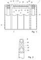
- einen Vertikalschnitt durch einen Flaschenkasten mit einem Boden, vier Seitenwänden und einem Mittelhandgriff, der an seiner Unterseite wellen-förmig gestaltet ist und drei übereinanderliegende wulst- bzw. rippenförmige Abschnitte aufweist,
- Fig.2
- einen Vertikalschnitt durch den in Fig. 1 dargestellten Mittelhandgriff,
- Fig.3
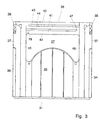
- einen Vertikalschnitt durch einen weiteren Flaschenkasten, bei dem in allen vier Seitenwänden Handgriffe mit darunter liegenden Durchgriffsöffnungen vorgesehen sind, wobei im Handgriff hintereinanderliegende wulstförmige Abschnitte angeordnet sind,
- Fig.4
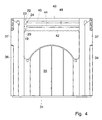
- einen Vertikalschnitt durch einen Flaschenkasten mit Handgriffen in den Seitenwänden wobei die wulstförmigen Abschnitte parallel zueinander angeordnet sind,
- Fig.5
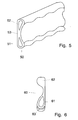
- eine schaubildliche Darstellung eines aufgeschnittenen Handgriffs, bei dem zwei parallel übereinander angeordnete wulstförmige Abschnitte vorgesehen sind, die weitgehend wellenförmig ausgebildet sind,
- Fig.6
- eine Schnittdarstellung eines Handgriffs mit an seiter Unterseite angebrachtem weicheren Material und
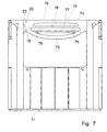
- Fig.7
- ein weiteres Ausführungsbeispiel eines Flaschenkastens mit in den Seitenwänden integrierten Handgriffen, mit einem bogenförmig verlaufenden unteren Abschnitt, wobei zwei horizontal verlaufende rippenförmige Abschnitte vorgesehen sind.
- Fig. 1
- 3 shows a vertical section through a bottle crate with a bottom, four side walls and a central handle, which is wave-shaped on its underside and has three overlapping beaded or rib-shaped sections,
- Fig. 2
- 2 shows a vertical section through the center handle shown in FIG. 1,
- Fig. 3
- 3 shows a vertical section through a further bottle crate, in which handles with underlying through openings are provided in all four side walls, bead-like sections lying one behind the other being arranged in the handle,
- Fig. 4
- a vertical section through a bottle crate with handles in the side walls, the bead-shaped sections being arranged parallel to one another,
- Fig. 5
- 2 shows a diagrammatic representation of a cut-open handle, in which two bead-shaped sections arranged in parallel one above the other are provided, which are largely undulating,
- Fig. 6
- a sectional view of a handle with softer material attached to the underside and
- Fig. 7
- a further embodiment of a bottle crate with handles integrated in the side walls, with an arcuate lower section, two horizontally running rib-shaped sections being provided.
Mit in Fig.1 1 ist ein Flaschenkasten bezeichnet, der einen Boden 2 und vier von
diesem aufragende Seitenwände 3, 4, 5 und 6 aufweist. In der Mitte des Bodens 2 ist
an diesem ein Handgriff 7 angeordnet, der bis in die Höhe des oberen Randes der
Seitenwände reicht. Dieser Handgriff 7 ist an seiner Unterseite wellenförmig
ausgebildet, wobei die Wellenform der Fingeranordnung an der menschlichen Hand
angepaßt ist. Der Handgriff 7 weist drei übereinander liegende Abschnitte 8, 9 und 10
auf, die wulstförmig ausgebildet sind. Dabei ist der obere und der untere Abschnitt 8
und 10 jeweils hohl ausgebildet und mit einem verhältnismäßig großen
Außendurchmesser hergestellt. Beide Abschnitte 8 und 10 weisen sowohl in ihrer
äußeren Form als auch in der Querschnittsform des Hohlraumes eine Tropfenform auf.
Der innere wulstförmige Abschnitt 9 hat dagegen einen etwas kleineren Durchmesser
und ist massiv ausgebildet. Der Kunststoff wird zum Bilden dieses Handgriffs 7 vom
Boden 2 her gleichzeitig durch die senkrechten Holme 11 und 12 in den eigentlichen
Handgriff geleitet, wobei die beiden Kunststoffströme normalerweise in der Mitte des
Handgriffs aufeinandertreffen und sich dort vereinigen. Aufgrund der bereits
eingetretenen teilweisen Abkühlung des Kunststoffes kann die Vereinigung nicht mehr
optimal sein, wodurch hier eine Schwachstelle des Handgriffs vorliegen würde. In den
drei übereinanderliegenden Abschnitten 8, 9 und 10 sind jeweils auf einer Seite
Fließbremsen 13, 14 und 15 in der Spritzform vorgesehen, welche die
Fließgeschwindigkeit des Kunststoffs herabsetzen. Dadurch wird die jeweilige
Zusammentreffstelle 16, 17 und 18 der beiden Kunststoffströme aus der Mitte des
Handgriffs in den Randbereich verschoben. Für die drei Abschnitte 8, 9 und 10 liegen
diese Zusammentreffstellen an jeweils unterschiedlichen Positionen, so daß der
Handgriff trotz eventuell vorliegender Schwachstellen eine optimale Festigkeit erhält.
Am einen Ende des Handgriffs 7 sind darüber hinaus zwei Anschlüsse 19 und 22 für
Druckgas vorgesehen, welches jeweils in den oberen bzw. den unteren Abschnitt 8 und
9 gelangt, wodurch diese beiden Abschnitte hohl ausgebildet werden. Eine weitere
Fließbremse 23 sorgt dafür, daß die beiden Druckgasströme keine gegenseitige
Verbindung eingehen und so gezielt nur in den jeweils zugeordneten Abschnitt
gelangen. Die Druckbeaufschlagung mit diesem Gas erfolgt dabei solange, bis der
Kunststoff abgekühlt ist und kein Schrumpf mehr erfolgen kann. Auch für den Fall,
daß die Spritzform bereits weitgehend mit Kunststoff ausgefüllt ist, wird dieses
Druckgas eingeleitet und der Gasdruck während des Abkühlens des Kunststoffs
aufrechterhalten, wodurch ein Schrumpfen des Kunststoffes beim Abkühlen
unterbunden wird. Hohlräume in den wulstförmigen Abschnitten können dabei
durchaus entstehen, die dann aber nicht über die volle Länge des jeweiligen
Abschnittes reichen.With in Fig.1 1 is a bottle crate, the
Wie besonders aus Fig.2 ersichtlich ist, sind die drei übereinander liegenden
wulstförmigen Abschnitte 8, 9 und 10 mittels zweier Stege 20 und 21 miteinander
verbunden. Der untere wulstförmige Abschnitt 10 ist im wesentlichen tropfenförmig
ausgebildet, wobei seine untere Fläche leicht abgeplattet und in Längsrichtung
wellenförmig ausgebildet ist. Der obere Abschnitt 8 hat eine ähnliche tropfenförmige
Gestalt und ist an seiner oberen Fläche leicht abgeplattet ausgebildet. Beide
wulstförmigen Abschnitte 8 und 10 sind hohl ausgebildet, wobei das hierzu
verwendete Druckgas durch die Öffnung 19 eingeblasen wurde und von dort
gleichzeitig in die beiden Abschnitte 8, 10 einströmt. Die innere Gestalt der beiden
Hohlräume ist dabei ebenfalls tropfenförmig. Infolge des geringeren freien
Querschnittes des Abschnittes 9 und der zusätzlichen Fließbremse 14 gelangt kein Gas
in den mittleren Abschnitt; gleichwohl wirkt der Gasdruck über den Kunststoff auch
auf diesen Abschnitt und verhindert auch dort - wie in den beiden anderen Abschnitten
und den Verbindungswegen - ein Einfallen derAußenflächen während des Abkühlens
des Kunststoffes und des damit einhergehenden Schrumpfens.As can be seen particularly from FIG. 2, the three are one above the other
bead-shaped
Durch die zweite Einström-Öffnung 22, die unmittelbar beim oberen Abschnitt 8
vorgesehen ist, wird ein optimales gleichzeitiges Einströmen des Druckgases in die
beiden Abschnitte 8 und 10 erreicht. Durch eine zwischen diesen beiden Einström-Öffnungen
19 und 22 vorgesehene Dünnstelle 23 wird verhindert, daß sich die beiden
Gasströme vereinigen. Auch an den beiden von den Einström-Öffnungen 19 und 22
abgewandten Enden der drei Abschnitte 8, 9 und 10 ist infolge der Fließbremsen 13
und 15 und der damit verbundenen Engstellen eine Verbindung der Gasströme nicht
möglich.Through the second inflow opening 22, which is located directly at the
Beim Ausführungsbeispiel nach Fig.3 sind in den Seitenwänden 33, 34, 35 und 36 des
Flaschenkastens 31 Durchgriffsöffnungen 37 vorgesehen, die an ihrer oberen Seite mit
einem Handgriff 38 abgeschlossen sind. Jeder dieser Handgriffe 38 enthält drei
übereinander liegende wulst- bzw. rippenförmige Abschnitte 40, 41 und 42, von denen
nur der untere Abschnitt 42 hohl ausgebildet ist. Die drei wulst- bzw. rippenförmigen
Abschnitte 40, 41 und 42 sind über Stege 43 und 44, die einen verhältnismäßig
geringen Querschnitt aufweisen, miteinander verbunden. Der gesamte Handgriff wird
über die beiden senkrechten Holme 45 und 46 mit flüssigem Kunststoff versorgt, der
gleichzeitig in die drei Abschnitte 40, 41, 42 und die beiden Stege 43, 44 gelangt.
Gleichzeitig wird durch die Einström-Öffnung 19 Druckgas in den unteren Abschnitt
42 eingepreßt, das dort einen Hohlraum ausbildet. Am Ende des Abschnittes 42 wirkt
das Druckgas zwar solange sein Druck aufrechterhalten wird auf den Kunststoff in den
weiteren Abschnitten 40 und 41 bzw. den Stegen 43 und 44, kann jedoch dort
aufgrund der geringen Querschnitte bzw. der vorgesehenen Fließbremse 47 keinen
Hohlraum ausbilden. Die Unterseite des Handgriffs 38 ist wieder wellenförmig
ausgebildet.In the embodiment of Figure 3 in the
Beim in Fig.4 dargestellten Ausführungsbeispiel sind im sonst gegenüber Fig.3
gleichen Flaschenkasten 31 drei parallelle wulstförmige Abschnitte 42, 48 und 49
angeordnet, die durch Stege 43 und 44 miteinander verbunden sind. Im Bereich jedes
der Abschnitte 42,48,49 ist eine Einblasöffnung 19, 22, 24 vorgesehen, über welche
Druckgas in die einzelnen Abschnitte gelangt und diese hohl ausbildet. Zwischen
diesen drei Einblasöffnungen sind zwei Fließbremsen 23 vorgesehen, welche ein
Durchbrechen des Druckgases in den jeweils anderen Hohlraum verhindern.In the embodiment shown in Figure 4 are otherwise compared to Figure 3
In Fig.5 ist ein Handgriff 50 dargestellt, der zwei übereinanderliegende wulstförmige
Abschnitte 51 und 52 aufweist. Beide Abschnitte sind im Querschnitt tropfenförmig
ausgebildet und durch einen Steg 53 miteinander verbunden. Im Inneren sind die
beiden wulstförmigen Abschnitte 51, 52 ebenfalls tropfenförmig ausgebildet, wobei
die beiden Hohlräume durch getrenntes Einblasen von Druckgas entstanden sind. Der
untere der beiden Abschnitte ist sowohl an seiner Unterseite als auch an seiner freien
Oberseite wellenförmig ausgebildet. Auch die freie Unterseite des oberen Abschnittes
52 ist wellenförmig gestaltet. Dadurch erfahren die Finger bzw. Fingerspitzen in den
Wellentälern einen sehr guten seitlichen Halt.In Figure 5, a
Beim Ausführungsbeispiel nach Fig.6 ist lediglich der untere wulstförmige Abschnitt
61 des Handgriffs 60 hohl ausgebildet und hat sowohl außen als auch innen eine
tropfenförmige Gestalt. Der obere Abschnitt 62 ist im Querschnitt ebenfalls
tropfenförmig gestaltet; eine Hohlraumausbildung hat hier jedoch nicht stattgefunden.
An der Unterseite des unteren Abschnitte 61 ist eine Lage 63 aus weicherem
Kunststoffmaterial vorgesehen, welche die untere Abschlußfläche bildet. Diese Lage
63 wird durch eine getrennte, nicht dargestellte Einspritzdüse in diesen Bereich
eingespritzt und zwar nach dem Spritzen des eigentlichen Kastens. Es ist jedoch auch
möglich, diese Lage 63 getrennt herzustellen und entweder vor dem Spritzen des
Kastens in die Spritzform einzulegen oder nachträglich am fertigen Kasten
anzubringen.In the exemplary embodiment according to FIG. 6, only the lower bead-shaped section is
61 of the
Beim in Fig.7 dargestellten Ausführungsbeispiel ist die untere Begrenzung des
Handgriffs 70 des Kastens 71 gewölbt ausgebildet. Damit verläuft auch der untere
wulstförmige Abschnitt 72 bogenförmig. Der obere wulstförmige Abschnitt 73 und
zwei dazwischen liegende rippenförmige Abschnitte 74 und 75 verlaufen dagegen
geradlinig. Auch hier sind wieder Stege 76, 77 und 78 zwischen den benachbarten
Abschnitten vorgesehen. Durch die beiden Einström-Öffnungen 19 und 23, die durch
eine Fließbremse 23 von einander abgeschirmt sind, gelangt wieder Druckgas in den
unteren und den oberen wulstförmigen Abschnitt 72 und 73, wodurch diese
unabhängig von einander hohl ausgebildet werden. In den beiden Schmalseitenwänden
des Kastens 71 können auch anstelle der gewölbt ausgebildeten Handgriffe 70 gerade
ausgebildete Handgriffe vorgesehen sein, wie sie beispielsweise in den Fig.3 und 4
dargestellt sind. Es können aber auch hier an der Unterseite bogenförmig ausgebildete
Handgriffe eingesetzt werden.In the embodiment shown in Figure 7, the lower limit of
Claims (15)
- Crate (1), for bottles in particular, that is manufactured from plastic by the injection-moulding process, with a base (2) and at least one handle (7, 38, 50, 60, 70) for carrying the crate (1), this handle (7, 38, 50, 60, 70) being provided at least at the top and at the bottom with a bead-shaped section (8, 10; 40, 42; 49; 51, 52; 61, 62; 72, 73) that extends in the longitudinal direction of the handle, at least one of which is made to be hollow along at least part of its horizontal length by the injection of gas, wherein the bead-shaped section (51) located on the lower edge of the handle (50) is wave-shaped both on its lower edge and its free upper edge, with the waves extending at right angles to the longitudinal direction of the handle and being shaped to correspond to the fingers of the human hand.
- Crate according to claim 1, wherein the bead-shaped section (52) provided on the upper edge of the handle (50) is wave-shaped on its free lower edge.
- Crate according to claim 1 or 2, wherein the cross-section of at least the bead-shaped section (10, 42, 51, 61, 71) located on the lower edge of the handle (7, 38, 50, 60, 70) is at least approximately drop-shaped.
- Crate according to claim 1, 2 or 3, wherein at least one further rib-shaped section (9, 41, 48, 74, 75) is provided between the two bead-shaped sections (8, 10; 40, 42; 42, 49; 71, 72).
- Crate according to one of claims 1 to 4, wherein the bead- and/or rib-shaped sections (8, 9, 10; 40, 41, 42; 42, 48, 49; 61, 62; 72, 73, 74, 75) are connected to each other.
- Crate according to one of the previous claims, wherein at least the upper and lower bead-shaped sections (8, 10; 42, 49; 51, 52; 72, 73) are provided with a hollow cavity by separate gas injection operations so that the cavities are not connected in any way.
- Crate according to one of the previous claims, wherein flow brakes (13, 14, 15, 23, 47) are provided for the flows of plastic in the handle area, which on the one hand reduce the flow speed of the plastic and on the other hand prevent gas penetration.
- Crate according to one of the previous claims, wherein the lower bead-shaped section (72) of the handle (70) extends in a curve and the handle therefore has a convex shape on its lower edge.
- Crate, for bottles in particular, that is manufactured from plastic by the injection-moulding process, with a handle that consists of at least two bead-shaped sections located above each other, particularly according to one of the previous claims, wherein at least the lower outer edge of the lower bead-shaped section (61) is produced from a softer plastic material (layer 63).
- Crate according to claim 9, wherein the softer plastic material (layer 63) is also fed into the mould by the injection-moulding process and is covered on the inside by the plastic material used to produce the rest of the crate.
- Crate according to claim 9, wherein the softer plastic material is produced as a separate component (layer 63) and is loaded in the injection mould before the rest of the crate is injection-moulded.
- Crate according to claim 9, wherein the softer plastic material is produced as a separate component (layer 63) and is attached to the handle (60) subsequently.
- Crate according to claim 10, 11 or 12, wherein the lower outer edge (layer 63) of the handle (60) and the rest of the crate are produced from a related plastic.
- Crate according to claim 10, 11, 12 or 13, wherein not only the lower outer edge (layer 63) of the handle (60) but also the rest of the crate are produced from polyethylene, albeit of different hardness.
- Process for the production of a crate - for bottles in particular - from plastic, that is provided with at least one handle (7, 38, 50, 60, 70) and has a base (2), according to one of the previous claims, the liquid plastic being injected into an injection mould from the base (2) of the crate, the plastic moving into the area of the handle from the base of the crate and flowing into the handle simultaneously from two opposite ends of the handle, with the bead- and/or rib-shaped sections located above each other being flowed into at different flow speeds and with gas being forced into the channels for formation of the bead- and/or rib-shaped sections (8, 9, 10; 40, 41, 42; 42, 48, 49; 51, 52; 61, 62; 72, 73, 74, 75) while the plastic is still liquid and with the gas pressure being maintained until the plastic has cooled off at least to some extent, wherein two different plastics are injected into the area of the handle (60), the plastic that is softer after the end of the solidification process being positioned on the lower outer edge of the handle, while the other plastic fills out the rest of the injection mould.
Priority Applications (3)
| Application Number | Priority Date | Filing Date | Title |
|---|---|---|---|
| AT95116856T ATE188936T1 (en) | 1995-10-26 | 1995-10-26 | BOX, IN PARTICULAR BOTTLE BOX, AND METHOD FOR PRODUCING SUCH A BOX |
| EP95116856A EP0770552B1 (en) | 1995-10-26 | 1995-10-26 | Bottle crates and method for manufacturing such crates |
| DE59507654T DE59507654D1 (en) | 1995-10-26 | 1995-10-26 | Crate, in particular bottle crate and method for producing such a crate |
Applications Claiming Priority (1)
| Application Number | Priority Date | Filing Date | Title |
|---|---|---|---|
| EP95116856A EP0770552B1 (en) | 1995-10-26 | 1995-10-26 | Bottle crates and method for manufacturing such crates |
Publications (2)
| Publication Number | Publication Date |
|---|---|
| EP0770552A1 EP0770552A1 (en) | 1997-05-02 |
| EP0770552B1 true EP0770552B1 (en) | 2000-01-19 |
Family
ID=8219749
Family Applications (1)
| Application Number | Title | Priority Date | Filing Date |
|---|---|---|---|
| EP95116856A Expired - Lifetime EP0770552B1 (en) | 1995-10-26 | 1995-10-26 | Bottle crates and method for manufacturing such crates |
Country Status (3)
| Country | Link |
|---|---|
| EP (1) | EP0770552B1 (en) |
| AT (1) | ATE188936T1 (en) |
| DE (1) | DE59507654D1 (en) |
Families Citing this family (10)
| Publication number | Priority date | Publication date | Assignee | Title |
|---|---|---|---|---|
| IT244854Y1 (en) * | 1998-06-05 | 2002-03-14 | Tontarelli Sergio | PRINTED PLASTIC BOX EQUIPPED WITH A HIGH PERFORMANCE EDGE WITH HIGH RIGIDITY FEATURES |
| NL1010724C2 (en) * | 1998-12-04 | 2000-06-06 | Wavin Trepak B V | Double walled crate for bottles is made from injection molded plastic and has softened handgrips to minimize discomfort for user |
| DE10239319B4 (en) * | 2002-08-27 | 2007-04-19 | Schoeller Wavin Systems Services Gmbh | Two-component plastic container |
| GB2394218A (en) * | 2002-10-17 | 2004-04-21 | D W Plastics Nv | Container having a handle |
| EP1484154A1 (en) * | 2003-06-06 | 2004-12-08 | Plamatec AG | Multimaterial injection molding using the core-back process |
| DE202004018927U1 (en) | 2004-12-07 | 2005-02-24 | Ifco Systems Gmbh | Transport box with hinged side parts made of plastic |
| EP1990174A1 (en) * | 2007-05-11 | 2008-11-12 | D.W. Plastics N.V. | Injection moulded crate |
| KR101156260B1 (en) * | 2007-12-27 | 2012-06-13 | 도카이 고교 가부시키가이샤 | Container having handling hole for transportation and opening and closing member of handling hole and manufacturing process of opening and closing member |
| WO2011015214A1 (en) | 2009-08-05 | 2011-02-10 | Schoeller Arca Systems Gmbh | Bottle crate |
| DE202015106211U1 (en) * | 2015-11-17 | 2017-02-20 | bekuplast Gesellschaft mit beschränkter Haftung | Plastic container |
Family Cites Families (9)
| Publication number | Priority date | Publication date | Assignee | Title |
|---|---|---|---|---|
| DE3940186A1 (en) * | 1989-12-05 | 1991-06-06 | Rudolf Koose | Moulding crates with hollow handles - by injection moulding crate with solid handle, forming an outlet from cavity, and blowing out core of handle while still soft |
| DE4022884A1 (en) * | 1990-07-18 | 1992-01-23 | Schoeller Plast Ag | Plastic bottle crate - has handle core and outer portion with different degrees of hardness |
| DE4035497C2 (en) * | 1990-11-08 | 1994-08-11 | Peguform Werke Gmbh | Device for the production of transport boxes, in particular bottle boxes |
| NL9002485A (en) * | 1990-11-14 | 1992-06-01 | Wavin Bv | PLASTIC CRATE WITH PARTLY HOLLOW HANDLE. |
| FR2674219B1 (en) * | 1991-03-18 | 1993-06-11 | Allibert Sa | LOCKER IN MOLDED PLASTIC MATERIAL AND METHOD FOR STORING SUCH LOCKERS. |
| US5145082A (en) * | 1991-09-10 | 1992-09-08 | Craft Jr Charles W | Handle reinforcement mechanism for laundry basket |
| DK0603531T3 (en) * | 1992-12-23 | 1997-08-11 | Schoeller Plast Ag | Plastic box with a handle |
| DE9418484U1 (en) * | 1994-11-22 | 1995-01-12 | Götz, Wilhelm, 88410 Bad Wurzach | Plastic case |
| EP0687630B1 (en) * | 1994-06-17 | 1999-08-25 | Wilhelm Götz | Plastic part made by injection moulding |
-
1995
- 1995-10-26 DE DE59507654T patent/DE59507654D1/en not_active Expired - Lifetime
- 1995-10-26 AT AT95116856T patent/ATE188936T1/en not_active IP Right Cessation
- 1995-10-26 EP EP95116856A patent/EP0770552B1/en not_active Expired - Lifetime
Also Published As
| Publication number | Publication date |
|---|---|
| EP0770552A1 (en) | 1997-05-02 |
| DE59507654D1 (en) | 2000-02-24 |
| ATE188936T1 (en) | 2000-02-15 |
Similar Documents
| Publication | Publication Date | Title |
|---|---|---|
| EP0528754B1 (en) | Process and apparatus for producing a plastic bottle | |
| EP0770552B1 (en) | Bottle crates and method for manufacturing such crates | |
| DE2918926C2 (en) | Injection mold for the production of injection molded parts consisting of at least two different plastic compounds and having at least two different areas | |
| EP0396728B2 (en) | Plastic bottle-case | |
| DE4226390C2 (en) | Hollow body injection molding process | |
| DE68902446T2 (en) | PLASTIC CHEESE MOLD WITH DRAINAGE GROOVES SHAPED BY INJECTION MOLDING. | |
| DE10252648A1 (en) | Container molding process, particularly for a grip or base area of a bottle crate, involves molding a first section on a container and transfer to a second tool whose slides form cavities for molding second sections | |
| DE69905786T2 (en) | Method and device for producing a cast surface fastener and surface fastener thus produced | |
| EP0687630B1 (en) | Plastic part made by injection moulding | |
| DE4236781A1 (en) | Bottle case with carrying grips - is of plastic with grip openings in side walls and limited upwardly by grip section. | |
| EP0204200B1 (en) | Method and apparatus for blow-moulding hollow articles made from thermoplastic material | |
| DE69628164T2 (en) | Process for the production of injection molded articles, apparatus for carrying out this process and new molded articles | |
| DE1179356B (en) | Device for producing hoses from thermoplastic material, in particular thermoplastic plastics | |
| DE3839087C2 (en) | Plastic bottle crate and method of making the same | |
| EP0189906B1 (en) | Mould for injection-moulding stackable containers | |
| DE8912048U1 (en) | Plastic boxes, especially bottle boxes | |
| DE2116940B1 (en) | METHOD AND DEVICE FOR EXTRUSION OF PROFILE STRIPS FROM A THERMOPLASTIC | |
| DE19932515A1 (en) | Open-sided plastic box particularly suitable for transport and display of fruit and vegetables, has inverted U-shaped bar-handles incorporating gas-injection molded cavity | |
| DE9418484U1 (en) | Plastic case | |
| DE4230782C2 (en) | Method and device for injection molding a molded body with a plastic cavity | |
| EP2633968B1 (en) | Method for producing a plastic container and plastic container | |
| EP0484763B1 (en) | Method and apparatus for making transport crates, in particular crates for bottles | |
| EP1636101B1 (en) | Plastic container comprising an insert | |
| DE10016973A1 (en) | Molding of a carrying handle, used for plastic crates for bottles, uses an injection of a gas medium into the mold to form hollow zones in the handle sections which contract on cooling | |
| DE2815802C3 (en) | Method and device for the production of plastic parts |
Legal Events
| Date | Code | Title | Description |
|---|---|---|---|
| PUAI | Public reference made under article 153(3) epc to a published international application that has entered the european phase |
Free format text: ORIGINAL CODE: 0009012 |
|
| AK | Designated contracting states |
Kind code of ref document: A1 Designated state(s): AT BE CH DE DK ES FR GR IT LI LU NL SE |
|
| AX | Request for extension of the european patent |
Free format text: SI PAYMENT 951115 |
|
| 17P | Request for examination filed |
Effective date: 19970917 |
|
| 17Q | First examination report despatched |
Effective date: 19980406 |
|
| GRAG | Despatch of communication of intention to grant |
Free format text: ORIGINAL CODE: EPIDOS AGRA |
|
| GRAG | Despatch of communication of intention to grant |
Free format text: ORIGINAL CODE: EPIDOS AGRA |
|
| GRAH | Despatch of communication of intention to grant a patent |
Free format text: ORIGINAL CODE: EPIDOS IGRA |
|
| GRAH | Despatch of communication of intention to grant a patent |
Free format text: ORIGINAL CODE: EPIDOS IGRA |
|
| GRAA | (expected) grant |
Free format text: ORIGINAL CODE: 0009210 |
|
| AK | Designated contracting states |
Kind code of ref document: B1 Designated state(s): AT BE CH DE DK ES FR GR IT LI LU NL SE |
|
| AX | Request for extension of the european patent |
Free format text: SI PAYMENT 19951115 |
|
| PG25 | Lapsed in a contracting state [announced via postgrant information from national office to epo] |
Ref country code: SE Free format text: THE PATENT HAS BEEN ANNULLED BY A DECISION OF A NATIONAL AUTHORITY Effective date: 20000119 Ref country code: NL Free format text: LAPSE BECAUSE OF FAILURE TO SUBMIT A TRANSLATION OF THE DESCRIPTION OR TO PAY THE FEE WITHIN THE PRESCRIBED TIME-LIMIT Effective date: 20000119 Ref country code: IT Free format text: LAPSE BECAUSE OF FAILURE TO SUBMIT A TRANSLATION OF THE DESCRIPTION OR TO PAY THE FEE WITHIN THE PRE;WARNING: LAPSES OF ITALIAN PATENTS WITH EFFECTIVE DATE BEFORE 2007 MAY HAVE OCCURRED AT ANY TIME BEFORE 2007. THE CORRECT EFFECTIVE DATE MAY BE DIFFERENT FROM THE ONE RECORDED.SCRIBED TIME-LIMIT Effective date: 20000119 Ref country code: GR Free format text: LAPSE BECAUSE OF NON-PAYMENT OF DUE FEES Effective date: 20000119 Ref country code: FR Free format text: LAPSE BECAUSE OF FAILURE TO SUBMIT A TRANSLATION OF THE DESCRIPTION OR TO PAY THE FEE WITHIN THE PRESCRIBED TIME-LIMIT Effective date: 20000119 Ref country code: ES Free format text: THE PATENT HAS BEEN ANNULLED BY A DECISION OF A NATIONAL AUTHORITY Effective date: 20000119 |
|
| REF | Corresponds to: |
Ref document number: 188936 Country of ref document: AT Date of ref document: 20000215 Kind code of ref document: T |
|
| REG | Reference to a national code |
Ref country code: CH Ref legal event code: EP |
|
| REF | Corresponds to: |
Ref document number: 59507654 Country of ref document: DE Date of ref document: 20000224 |
|
| PG25 | Lapsed in a contracting state [announced via postgrant information from national office to epo] |
Ref country code: DK Free format text: LAPSE BECAUSE OF FAILURE TO SUBMIT A TRANSLATION OF THE DESCRIPTION OR TO PAY THE FEE WITHIN THE PRESCRIBED TIME-LIMIT Effective date: 20000419 |
|
| EN | Fr: translation not filed | ||
| NLV1 | Nl: lapsed or annulled due to failure to fulfill the requirements of art. 29p and 29m of the patents act | ||
| PG25 | Lapsed in a contracting state [announced via postgrant information from national office to epo] |
Ref country code: LU Free format text: LAPSE BECAUSE OF NON-PAYMENT OF DUE FEES Effective date: 20001026 Ref country code: AT Free format text: LAPSE BECAUSE OF NON-PAYMENT OF DUE FEES Effective date: 20001026 |
|
| PG25 | Lapsed in a contracting state [announced via postgrant information from national office to epo] |
Ref country code: LI Free format text: LAPSE BECAUSE OF NON-PAYMENT OF DUE FEES Effective date: 20001031 Ref country code: CH Free format text: LAPSE BECAUSE OF NON-PAYMENT OF DUE FEES Effective date: 20001031 Ref country code: BE Free format text: LAPSE BECAUSE OF NON-PAYMENT OF DUE FEES Effective date: 20001031 |
|
| PLBE | No opposition filed within time limit |
Free format text: ORIGINAL CODE: 0009261 |
|
| STAA | Information on the status of an ep patent application or granted ep patent |
Free format text: STATUS: NO OPPOSITION FILED WITHIN TIME LIMIT |
|
| 26N | No opposition filed | ||
| BERE | Be: lapsed |
Owner name: GOTZ WILHELM Effective date: 20001031 |
|
| REG | Reference to a national code |
Ref country code: CH Ref legal event code: PL |
|
| PGFP | Annual fee paid to national office [announced via postgrant information from national office to epo] |
Ref country code: DE Payment date: 20150323 Year of fee payment: 20 |
|
| REG | Reference to a national code |
Ref country code: DE Ref legal event code: R071 Ref document number: 59507654 Country of ref document: DE |