EP0396728B2 - Plastic bottle-case - Google Patents
Plastic bottle-case Download PDFInfo
- Publication number
- EP0396728B2 EP0396728B2 EP89913218A EP89913218A EP0396728B2 EP 0396728 B2 EP0396728 B2 EP 0396728B2 EP 89913218 A EP89913218 A EP 89913218A EP 89913218 A EP89913218 A EP 89913218A EP 0396728 B2 EP0396728 B2 EP 0396728B2
- Authority
- EP
- European Patent Office
- Prior art keywords
- crate
- handle
- gas
- bottle
- hollow
- Prior art date
- Legal status (The legal status is an assumption and is not a legal conclusion. Google has not performed a legal analysis and makes no representation as to the accuracy of the status listed.)
- Expired - Lifetime
Links
Images
Classifications
-
- B—PERFORMING OPERATIONS; TRANSPORTING
- B29—WORKING OF PLASTICS; WORKING OF SUBSTANCES IN A PLASTIC STATE IN GENERAL
- B29C—SHAPING OR JOINING OF PLASTICS; SHAPING OF MATERIAL IN A PLASTIC STATE, NOT OTHERWISE PROVIDED FOR; AFTER-TREATMENT OF THE SHAPED PRODUCTS, e.g. REPAIRING
- B29C45/00—Injection moulding, i.e. forcing the required volume of moulding material through a nozzle into a closed mould; Apparatus therefor
- B29C45/17—Component parts, details or accessories; Auxiliary operations
- B29C45/1703—Introducing an auxiliary fluid into the mould
- B29C45/1704—Introducing an auxiliary fluid into the mould the fluid being introduced into the interior of the injected material which is still in a molten state, e.g. for producing hollow articles
-
- B—PERFORMING OPERATIONS; TRANSPORTING
- B65—CONVEYING; PACKING; STORING; HANDLING THIN OR FILAMENTARY MATERIAL
- B65D—CONTAINERS FOR STORAGE OR TRANSPORT OF ARTICLES OR MATERIALS, e.g. BAGS, BARRELS, BOTTLES, BOXES, CANS, CARTONS, CRATES, DRUMS, JARS, TANKS, HOPPERS, FORWARDING CONTAINERS; ACCESSORIES, CLOSURES, OR FITTINGS THEREFOR; PACKAGING ELEMENTS; PACKAGES
- B65D1/00—Containers having bodies formed in one piece, e.g. by casting metallic material, by moulding plastics, by blowing vitreous material, by throwing ceramic material, by moulding pulped fibrous material, by deep-drawing operations performed on sheet material
- B65D1/22—Boxes or like containers with side walls of substantial depth for enclosing contents
- B65D1/24—Boxes or like containers with side walls of substantial depth for enclosing contents with moulded compartments or partitions
- B65D1/243—Crates for bottles or like containers
-
- B—PERFORMING OPERATIONS; TRANSPORTING
- B29—WORKING OF PLASTICS; WORKING OF SUBSTANCES IN A PLASTIC STATE IN GENERAL
- B29L—INDEXING SCHEME ASSOCIATED WITH SUBCLASS B29C, RELATING TO PARTICULAR ARTICLES
- B29L2031/00—Other particular articles
- B29L2031/712—Containers; Packaging elements or accessories, Packages
- B29L2031/7134—Crates, e.g. for bottles
-
- B—PERFORMING OPERATIONS; TRANSPORTING
- B65—CONVEYING; PACKING; STORING; HANDLING THIN OR FILAMENTARY MATERIAL
- B65D—CONTAINERS FOR STORAGE OR TRANSPORT OF ARTICLES OR MATERIALS, e.g. BAGS, BARRELS, BOTTLES, BOXES, CANS, CARTONS, CRATES, DRUMS, JARS, TANKS, HOPPERS, FORWARDING CONTAINERS; ACCESSORIES, CLOSURES, OR FITTINGS THEREFOR; PACKAGING ELEMENTS; PACKAGES
- B65D2501/00—Containers having bodies formed in one piece
- B65D2501/24—Boxes or like containers with moulded compartments or partitions
- B65D2501/24006—Details relating to bottle crates
- B65D2501/24012—Materials
- B65D2501/24019—Mainly plastics
-
- B—PERFORMING OPERATIONS; TRANSPORTING
- B65—CONVEYING; PACKING; STORING; HANDLING THIN OR FILAMENTARY MATERIAL
- B65D—CONTAINERS FOR STORAGE OR TRANSPORT OF ARTICLES OR MATERIALS, e.g. BAGS, BARRELS, BOTTLES, BOXES, CANS, CARTONS, CRATES, DRUMS, JARS, TANKS, HOPPERS, FORWARDING CONTAINERS; ACCESSORIES, CLOSURES, OR FITTINGS THEREFOR; PACKAGING ELEMENTS; PACKAGES
- B65D2501/00—Containers having bodies formed in one piece
- B65D2501/24—Boxes or like containers with moulded compartments or partitions
- B65D2501/24006—Details relating to bottle crates
- B65D2501/24363—Handles
- B65D2501/24509—Integral handles
- B65D2501/24528—Integral handles centrally located in open container
-
- B—PERFORMING OPERATIONS; TRANSPORTING
- B65—CONVEYING; PACKING; STORING; HANDLING THIN OR FILAMENTARY MATERIAL
- B65D—CONTAINERS FOR STORAGE OR TRANSPORT OF ARTICLES OR MATERIALS, e.g. BAGS, BARRELS, BOTTLES, BOXES, CANS, CARTONS, CRATES, DRUMS, JARS, TANKS, HOPPERS, FORWARDING CONTAINERS; ACCESSORIES, CLOSURES, OR FITTINGS THEREFOR; PACKAGING ELEMENTS; PACKAGES
- B65D2501/00—Containers having bodies formed in one piece
- B65D2501/24—Boxes or like containers with moulded compartments or partitions
- B65D2501/24006—Details relating to bottle crates
- B65D2501/24363—Handles
- B65D2501/24509—Integral handles
- B65D2501/24535—Integral handles formed in the walls, e.g. roughnings, cavities or projections
-
- B—PERFORMING OPERATIONS; TRANSPORTING
- B65—CONVEYING; PACKING; STORING; HANDLING THIN OR FILAMENTARY MATERIAL
- B65D—CONTAINERS FOR STORAGE OR TRANSPORT OF ARTICLES OR MATERIALS, e.g. BAGS, BARRELS, BOTTLES, BOXES, CANS, CARTONS, CRATES, DRUMS, JARS, TANKS, HOPPERS, FORWARDING CONTAINERS; ACCESSORIES, CLOSURES, OR FITTINGS THEREFOR; PACKAGING ELEMENTS; PACKAGES
- B65D2501/00—Containers having bodies formed in one piece
- B65D2501/24—Boxes or like containers with moulded compartments or partitions
- B65D2501/24006—Details relating to bottle crates
- B65D2501/24363—Handles
- B65D2501/24541—Hand holes
-
- B—PERFORMING OPERATIONS; TRANSPORTING
- B65—CONVEYING; PACKING; STORING; HANDLING THIN OR FILAMENTARY MATERIAL
- B65D—CONTAINERS FOR STORAGE OR TRANSPORT OF ARTICLES OR MATERIALS, e.g. BAGS, BARRELS, BOTTLES, BOXES, CANS, CARTONS, CRATES, DRUMS, JARS, TANKS, HOPPERS, FORWARDING CONTAINERS; ACCESSORIES, CLOSURES, OR FITTINGS THEREFOR; PACKAGING ELEMENTS; PACKAGES
- B65D2501/00—Containers having bodies formed in one piece
- B65D2501/24—Boxes or like containers with moulded compartments or partitions
- B65D2501/24006—Details relating to bottle crates
- B65D2501/24764—Reinforcements
- B65D2501/24789—Means used for reinforcing
- B65D2501/24802—Hollow integral ribs
-
- B—PERFORMING OPERATIONS; TRANSPORTING
- B65—CONVEYING; PACKING; STORING; HANDLING THIN OR FILAMENTARY MATERIAL
- B65D—CONTAINERS FOR STORAGE OR TRANSPORT OF ARTICLES OR MATERIALS, e.g. BAGS, BARRELS, BOTTLES, BOXES, CANS, CARTONS, CRATES, DRUMS, JARS, TANKS, HOPPERS, FORWARDING CONTAINERS; ACCESSORIES, CLOSURES, OR FITTINGS THEREFOR; PACKAGING ELEMENTS; PACKAGES
- B65D2501/00—Containers having bodies formed in one piece
- B65D2501/24—Boxes or like containers with moulded compartments or partitions
- B65D2501/24006—Details relating to bottle crates
- B65D2501/24866—Other details
- B65D2501/24872—Information, identification or detection means
- B65D2501/24898—Matter printed directly on the crate
Definitions
- the invention relates to a bottle crate made of plastic according to the preambles of claims 1 and 2 and methods for producing such bottle crates.
- Bottle crates made of plastic usually consist of two narrow and two long side walls and an open-structured box bottom, with a compartment division, possibly consisting of compartment walls preferably arranged crosswise, being arranged inside the box.
- bottle crates of this type usually have handles which are formed by simple through openings in the bottle crate. Between the upper box edge and the upper edge of the opening, a horizontally extending web is delimited, which serves as a horizontal handle.
- Such horizontal handles are usually produced in the manner of U, C or L cross-sectional profiles.
- the breaking stability of such carrying handles leaves something to be desired. Carrying handles can be torn out, particularly if boxes filled with full bottles are handled frequently.
- a bottle crate made of plastic with four side walls is already known, which has a crate bottom and at least one handle.
- stiffening channels are provided in the bottle crate at least in regions over the circumference, carrying handles can nevertheless be torn out.
- a bottle crate is also known from EP-A-0 258 549, which has a central handle for handling the crate.
- the center handle extends in the area of the center of the box from the box bottom or from the compartment walls of the compartments upwards in the form of an upside-down U made of two support legs and a crossbar serving as a handle that connects the support legs.
- a bottle crate with double-walled side walls and a double-walled base is known from US-A-3506 154
- the object of the invention is to produce a bottle crate made of plastic, which is characterized by a very high torsional rigidity. This torsional stiffness is to be achieved above all in the area of the handles, in particular in the area of the handles, and an increase in the breaking stability is also to be achieved in order to prevent the handles from tearing out even under heavy loads.
- Bottle crates are also to be produced which, with good torsional rigidity, have smooth outer surfaces which are easy to print on. Finally, the comfort of such bottle crates should be increased
- the open profile shape is deviated and, when the bottle case is produced, a cavity is formed within the material of the bottle case by specifically blowing gas under pressure into the still molten material stream to form the bottle case, so that the claim 1 closed hollow stiffening channels are formed at least in the web forming the handle of the bottle crate.
- the stiffening channels are closed to the outside.
- such a stiffening channel or cavity which is enclosed over the circumference by the material of the box wall, makes an extremely torsion-resistant design of a handle that can be realized in a box-shaped and thus as a closed profile, which increases the comfort and also a dirt accumulation largely prevented and, conversely, allows a good cleaning of the bottle crate.
- the rigidity of the crate can be increased accordingly in a known manner by targeted injection of hollow channels into critical areas of the bottle crate.
- largely smooth outer surfaces can be guaranteed, which simplify the cleaning of the bottle crates, simplify the handling of the crates and also increase the wearing comfort in the case of smooth grip surfaces.
- Side walls of the bottle crate can also advantageously be formed with closed hollow chambers, which are achieved by blowing gas into the still molten plastic during the molding process.
- the air can be blown in from the side edges, i.e. from the corner areas, or from the bottom of the box.
- the box can also be injection molded in reverse, which is particularly advantageous for the formation of horizontal handles with closed cavities.
- cavities can be achieved in a targeted manner on bottle crates by simultaneous or time-delayed injection of gas into the melt, the cavities not being visible from the outside.
- the gas is injected into the plastic melt through very narrow nozzles.
- the cavity formation can be influenced in a targeted manner by appropriate arrangement of the nozzles and alignment of the nozzles.
- the nozzles are expediently arranged in such a way that they are more or less stationary with the tool and the finished bottle crate is lifted off the nozzles during removal from the mold.
- the nozzles are arranged to be movable and are introduced for blowing in the gas, so that they extend into the melt flow. At the end of the flow process, the nozzles are withdrawn so that these small injection openings close automatically. In this way, closed hollow channels can be realized in a simple manner at the ends.
- the nozzles are preferably arranged as close as possible to the desired cavity.
- the measures according to the invention can be used to specifically achieve cavities which, according to the invention, contribute to increasing the torsional rigidity and the breaking strength in the area of the carrying handle.
- the handle there is no need to design the handle as U, C or L or other profiles for the purpose of optimizing the strength, which are rather unfavorable in terms of comfort.
- a self-contained box profile in a compact design can be realized in the area of the handle, which enables the handle to be gripped comfortably by hand.
- Another advantage of this targeted cavity formation in the handle area is that the cavities can be extended into the remaining wall of the bottle crate, so that the strength continues in the rest of the crate, which results in an increased breaking strength for the handle.
- the gas injection also leads to material savings in the manufacture of bottle crates.
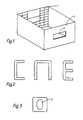
- Fig. 1 shows a purely schematic representation of a bottle crate with through openings 2 formed in the side walls, the cross bar remaining above the through openings 2, which also forms the upper edge of the crate, represents the actual handle 3 of the bottle crate. Furthermore, purely schematically in Fig. 1 on an inner wall of the bottle crate vertically and horizontally extending ribs 1 are shown, which serve to increase the torsional rigidity of the bottle crate.
- Fig. 2 shows conventional profile shapes of handles, whereas Fig. 3 shows a section through a handle 3, from which the shape of the hollow channel 6 is clearly shown. As Fig. 3 shows, the cross-sectional shape of the hollow channel is preferably oval, but depending on the embodiment also circular .
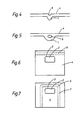
- FIG. 4 shows a conventional rib formation in a side wall 4, wherein a sink mark 5 can be seen quite clearly, which occurs due to the different mass accumulation in the rib area when the shaped bottle crate cools.
- 5 shows a rib design 1, in which a stiffening is achieved by a channel 6 produced by gas injection.
- the hollow channel 6 extends essentially over the entire length of the rib 1.
- FIG. 6 shows a side view of a bottle crate with a handle 3 above a penetration opening 2, a hollow channel 6 produced by gas injection being formed over the entire length of the side wall 4 at the upper edge.
- the hollow channel 6 is shown by dashed lines.
- the hollow channel 6 extends through the handle 3, so that there is a handle design according to FIG. 3.
- the gas is blown in from the bottom of the box, the gas flow being U-shaped and thus forming a U-shaped hollow channel 6, which results in a hollow design of the handle 3 and in stiffening of the side wall 4 of the box the hollow U-leg 7 of the hollow channel 6 leads.
- a very tear-resistant handle construction is realized.
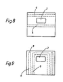
- two hollow channels 6 are formed on both sides of the access opening, which leads to a very high torsional rigidity of the bottle crate, in particular in the handle area.
- Such an embodiment is also particularly suitable for bottle crates with comparatively large openings in the side wall, which serve as display surfaces for the bottles accommodated in the crate. It is expedient here to align the hollow channels 6 along the edges of the window-like openings.
- a U-shaped hollow channel 6 is formed.
- the corner areas of the bottle crate are stiffened by vertically extending hollow channels 6, these hollow channels being closed at 8 at the top but being open at the bottom.
- the two lower ends which open into the floor are preferably closed, which also applies to the ends of the hollow channel 6, which is shown in FIGS. 6, 7 and 8.
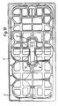
- FIG. 10 shows a bottle crate with a central handle 11, of which only the crossbar 12 serving as a carrying handle is shown in FIG. 10.
- the center handle extends either from the box bottom or from the compartment walls in the form of two opposite support legs 13, which open into the essentially horizontal crossbar 12 and are otherwise integrally formed with this as well as with the rest of the box.
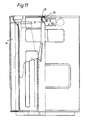
- this center handle 11 is formed over its entire length, i.e. over the length of the two support legs 13 and the length of the crossbar connecting the two support legs, as a closed hollow profile, as can be seen in particular from the section of the crossbar 12 in FIG. 11.
- the hollow profile of the center handle, designated 15, can either be closed or else open.
- the hollow profile is produced by blowing gas into the melt during the formation of the bottle crate, the gas flowing in the plastic core of the molded part to form the center handle without mixing with the material, and a cavity within the center handle as a result of the blown-in gas cushion.
- This cavity 15 is closed at both ends of the center handle 11, i.e. in the region of the junction with the box bottom and in the box walls, either by pulling off the nozzle before the material melt solidifies or the molding box from the nozzle before solidifying the material melt, i.e. is subtracted from the tool as a whole.
- the cavity can also be closed by other suitable measures.
- the hollow channel 15 in certain areas, in particular to form a cavity in the crosspiece 12, this cavity being able to extend to a certain extent into the edge region of the adjacent vertical support strips 13. It is also expedient to form a cavity in the substantial region of the vertical support legs 13, the cavity also advantageously being drawn slightly into the adjoining region of the crosspiece 12.
- gas can be blown in from both sides of the center handle. In a suitable embodiment, the gas was blown in at a pressure in the range of 200 bar.
- hollow profiles can also be provided in the area of the box walls by gas injection, for example in the box corners or in the support profiles designated 14 in the drawings, which extend vertically and one of which is shown in longitudinal section in FIG. 2.
- the invention relates to a bottle crate made of plastic according to the preambles of claims 1 and 2 and methods for producing such bottle crates.
- Bottle crates made of plastic usually consist of two narrow and two long side walls and an open-structured box bottom, with a compartment division, possibly consisting of compartment walls preferably arranged crosswise, being arranged inside the box.
- bottle crates of this type usually have handles which are formed by simple through openings in the bottle crate. Between the upper box edge and the upper edge of the opening, a horizontally extending web is delimited, which serves as a horizontal handle.
- Such horizontal handles are usually produced in the manner of U, C or L cross-sectional profiles. Apart from the fact that these grip profiles are still does not allow comfortable carrying behavior, the breaking stability of such handles leaves something to be desired. Carrying handles can be torn out, particularly if boxes filled with full bottles are handled frequently.
- a plastic bottle crate with four side walls is already known, which has a crate bottom and at least one handle. Although closed stiffening channels are provided in the bottle crate at least in some areas, carrying handles can still be torn out.
- a bottle crate is known from EP-A-0 258 549, which has a central handle for handling the crate.
- the center handle extends in the area of the center of the box from the box bottom or from the compartment walls of the compartments upwards in the form of an upside-down U made of two support legs and a crossbar serving as a handle that connects the support legs
- a bottle crate with double-walled side walls and a double-walled base is known from US-A-3 506 154
- document DE-A 38 23 650 is a republished national document.
- This document discloses a box, one embodiment of which box contains a cavity formed by gas injection during the spraying process. This cavity forms a hollow stiffening channel, which is obviously open at its ends, as is not to be expected otherwise with a gas injection.
- the open design of these stiffening channels in accordance with the above-mentioned document has considerable disadvantages.
- the object of the invention is to produce a bottle crate made of plastic, which is characterized by a very high torsional rigidity.
- This torsional stiffness is to be achieved above all in the area of the handles, in particular in the area of horizontal handles, and an increase in the breaking stability is also to be achieved in order to prevent the handles from tearing out even under heavy loads.
- bottle crates are to be produced which, with good torsional rigidity, have smooth outer surfaces which can be printed well. Finally, the wearing comfort of such bottle crates is to be increased.
- the open profile shape is deviated and, when the bottle case is produced, a cavity is formed within the material of the bottle case by specifically blowing gas under pressure into the still molten material stream to form the bottle case, so that the claim 1 closed hollow stiffening channels are formed at least in the web forming the handle of the bottle crate.
- the stiffening channels are closed to the outside.
- such a stiffening channel or cavity which is enclosed over the circumference by the material of the box wall, makes an extremely torsion-resistant design of a handle that can be realized in a box-shaped and thus as a closed profile, which increases the comfort and also a dirt accumulation largely prevented and, conversely, a good cleaning of the bottle crate allowed.
- the rigidity of the crate can be increased accordingly in a known manner by targeted injection of hollow channels into critical areas of the bottle crate. For example, it is advisable to make the corner profiles of the bottle crates hollow or vertically formed on the side walls make the supporting profiles hollow. Due to this design, rib structures can be avoided, which simplifies the cleaning of the bottle crates. As a result of the omission of the rib structures, largely smooth outer surfaces can be guaranteed, which simplify the cleaning of the bottle crates, simplify the handling of the crates and also increase the wearing comfort in the case of smooth grip surfaces.
- Side walls of the bottle crate can also advantageously be formed with closed hollow chambers, which are achieved by blowing gas into the still molten plastic during the molding process.
- the air can be blown in from the side walls, i.e. from the corner areas, or from the bottom of the box.
- the box can also be injection molded in reverse, which is particularly advantageous for the formation of horizontal handles with closed cavities.
- cavities can be achieved in a targeted manner on bottle crates by simultaneous or time-delayed injection of gas into the melt, the cavities not from the outside are evident.
- the gas is injected into the plastic melt through very narrow nozzles.
- the cavity formation can be influenced in a targeted manner by appropriate arrangement of the nozzles and alignment of the nozzles.
- the nozzles are expediently arranged in such a way that they are more or less stationary with the tool and the finished bottle crate is lifted off the nozzles during removal from the mold.
- the nozzles are arranged to be movable and are introduced for blowing in the gas, so that they extend into the melt flow. At the end of the flow process, the nozzles are withdrawn so that these small injection openings close automatically. In this way, closed hollow channels can be realized in a simple manner at the ends.
- the nozzles are preferably arranged as close as possible to the desired cavity.
- the measures according to the invention can be used to specifically achieve cavities which, according to the invention, contribute to increasing the torsional rigidity and the breaking strength in the area of the carrying handle.
- the handle there is no need to design the handle as U, C or L or other profiles for the purpose of optimizing the strength, which are rather unfavorable in terms of comfort. Rather, a self-contained box profile in a compact design can be realized in the area of the handle, which enables the handle to be gripped comfortably by hand.
- Another advantage of this targeted cavity formation in the handle area is that the cavities can be extended into the remaining wall of the bottle crate, so that the strength continues in the rest of the crate, which results in increased resistance to breakage for the handle Gas for material savings in the manufacture of bottle crates.
- Fig. 1 shows a purely schematic representation of a bottle crate with through openings 2 formed in the set walls, the transverse web remaining above the through openings 2, which also forms the upper edge of the crate, representing the actual handle 3 of the bottle crate. Furthermore, purely schematically in Fig. 1 on an inner wall of the bottle crate vertically and horizontally extending ribs 1 are shown, which serve to increase the torsional rigidity of the bottle crate.
- Fig. 2 shows conventional profile shapes of carrying handles, whereas Fig. 3 shows a section through a carrying handle 3, from which the shape of the hollow channel 6 is clearly shown. As shown in FIG. 3, the cross-sectional shape of the hollow channel is preferably oval, but, depending on the embodiment, also circular.
- Fig. 4 shows a conventional rib formation in a side wall 4, wherein a sink mark 5 can be seen quite clearly, which occurs due to the different mass accumulation in the rib area when the shaped bottle crate cools.
- Fig. 5 shows a rib formation 1, in which a stiffening by a Gas injection generated channel 6 is reached.
- the hollow channel 6 extends essentially over the entire length of the rib 1.
- Flg. 6 shows a side view of a bottle crate with a handle 3 above a passage opening 2, a hollow channel 6 produced by gas injection being formed over the entire length of the side wall 4 at the upper edge.
- the hollow channel 6 is shown by dashed lines.
- the hollow channel 6 extends through the handle 3, so that there is a handle design according to FIG. 3.
- the gas inlet is Solution from the box bottom, the gas flow is U-shaped and thus forms a U-shaped hollow channel 6, which leads to a hollow design of the handle 3 and a stiffening of the box side wall 4 due to the hollow U-legs 7 of the hollow channel 6 clearly a very tear-resistant handle construction is realized.
- FIG. 7 the embodiment according to FIG. 7
- two hollow channels 6 are formed on both sides of the access opening, which leads to a very high torsional rigidity of the bottle crate, in particular in the handle area.
- Such an embodiment is also particularly suitable for bottle crates with comparatively large openings in the side wall, which serve as display areas for the bottles accommodated in the crate. It is expedient here to align the hollow channels 6 along the edges of the window-like openings.
- a U-shaped hollow channel 6 is formed.
- the corner areas of the bottle crate are stiffened by vertically extending hollow channels 6, these hollow channels being closed at 8 at the top but being open at the bottom.
- the two lower ends which open into the floor are preferably closed, which also applies to the ends of the hollow channel 6, which is shown in FIGS. 6, 7 and 8.
- FIG. 10 shows a bottle crate with a central handle 11, of which only the crossbar 12 serving as a carrying handle is shown in FIG. 10.
- the center handle extends either from the box bottom or from the compartment walls in the form of two opposite support legs 13, which open into the essentially horizontal crossbar 12 and are otherwise integrally formed with this as well as with the rest of the box.
- this center handle 11 is formed over its entire length, i.e. over the length of the two support legs 13 and the length of the crossbar connecting the two support legs, as a closed hollow profile, as can be seen in particular from the section of the crossbar 12 in FIG. 11.
- the hollow profile of the center handle, designated 15, can either be closed or else open.
- the hollow profile is produced by blowing gas into the melt during the formation of the bottle crate, the gas flowing in the plastic core of the molded part to form the center handle without mixing with the material, and a cavity within the center handle as a result of the blown-in gas cushion.
- This cavity 15 is closed at both ends of the middle handle 11, i.e. in the region of the junction with the box bottom and in the box walls, either by pulling off the nozzle before the material melt solidifies or the molding box from the nozzle before solidifying the material melt, i.e. is subtracted from the tool as a whole.
- the cavity can also be closed by other suitable measures.
- the hollow channel 15 in certain areas, in particular to form a cavity in the crosspiece 12, this cavity being able to extend to a certain extent into the edge region of the adjacent vertical support strips 13. It is also expedient to form a cavity in the substantial region of the vertical support legs 13, the cavity also advantageously being drawn slightly into the adjoining region of the crosspiece 12.
- gas can be blown in from both sides of the center handle. In a suitable embodiment, the gas was blown in at a pressure in the range of 200 bar.
- hollow profiles can also be provided in the area of the box walls by gas injection, for example in the box corners or in the support profiles designated 14 in the drawings, which extend vertically and one of which is shown in longitudinal section in FIG. 2
Abstract
Description
Die Erfindung betrifft einen Flaschenkasten aus Kunststoff gemäß den Oberbegriffen der Patentansprüche 1 und 2 sowie Verfahren zur Herstellung solcher Flaschenkästen.The invention relates to a bottle crate made of plastic according to the preambles of
Flaschenkästen aus Kunststoff bestehen üblicherweise aus zwei schmalen und zwei langen Seitenwänden und einem offen strukturierten Kastenboden, wobei gegebenenfalls im Kasteninneren eine Facheinteilung, bestehend aus vorzugsweise über Kreuz angeordneten Fachwänden, angeordnet ist. Zum Tragen weisen derartige Flaschenkästen zumeist Handgriffe auf, die durch einfache Durchgriffsöffnungen des Flaschenkastens gebildet sind. Zwischen oberem Kastenrand und dem oberen Rand der Öffnung wird ein horizontal verlaufender Steg begrenzt, der als Horizontaler Tragegriff dient.Bottle crates made of plastic usually consist of two narrow and two long side walls and an open-structured box bottom, with a compartment division, possibly consisting of compartment walls preferably arranged crosswise, being arranged inside the box. For carrying, bottle crates of this type usually have handles which are formed by simple through openings in the bottle crate. Between the upper box edge and the upper edge of the opening, a horizontally extending web is delimited, which serves as a horizontal handle.
Üblicherweise werden derartige horizontale Tragegriffe in Art von U-, C- oder L-Querschnittsprofilen hergestellt. Abgesehen davon, daß diese Griffprofile noch kein komfortables Trageverhalten ermöglichen, läßt die Bruchstabilität solcher Tragegriffe zu wünschen übrig. Insbesondere bei häufiger Handhabung von mit vollen Flaschen gefüllten Kästen kann es zu einem Ausreißen von Tragegriffen kommen.Such horizontal handles are usually produced in the manner of U, C or L cross-sectional profiles. In addition to the fact that these grip profiles do not yet allow comfortable carrying behavior, the breaking stability of such carrying handles leaves something to be desired. Carrying handles can be torn out, particularly if boxes filled with full bottles are handled frequently.
Aus der FR-A- 2 223 248 ist bereits ein Flaschenkasten aus Kunststoff mit vier Seitenwänden bekannt, der einen Kastenboden und mindestens einen Handgriff aufweist Obwohl im Flaschenkasten zumindest bereichsweise über den Umfang geschlossene Versteifungskanäle vorgesehen sind, kann es dennoch zum Ausreißen von Traggriffen kommen.From FR-A-2 223 248 a bottle crate made of plastic with four side walls is already known, which has a crate bottom and at least one handle. Although stiffening channels are provided in the bottle crate at least in regions over the circumference, carrying handles can nevertheless be torn out.
Des weiteren ist aus der EP-A- 0 289 230 bzw. der GB-A- 2 158 002 bereits bekannt, beim Spritzen von Kunststoffteilen Hohlräume durch das Einblasen von Inertgas herzustellen.Furthermore, it is already known from EP-A-0 289 230 and GB-A-2 158 002, respectively, to produce cavities by injecting inert gas when molding plastic parts.
Außerdem ist aus der EP-A- 0 258 549 ein Flaschenkasten bekannt, der einen Mittelhandgriff zur Handhabung des Kastens aufweist. Der Mittelhandgriff erstreckt sich im Bereich der Kastenmitte vom Kastenboden oder von den Fachwänden der Facheinteilungen aus nach oben in Form eines auf dem Kopf stehenden U aus zwei Stützschenkeln und einem als Tragegriff dienenden, die Stützschenkel verbindenden Quersteg.A bottle crate is also known from EP-A-0 258 549, which has a central handle for handling the crate. The center handle extends in the area of the center of the box from the box bottom or from the compartment walls of the compartments upwards in the form of an upside-down U made of two support legs and a crossbar serving as a handle that connects the support legs.
AusderUS-A-3506 154 ist ein Flaschenkasten mit doppelwanding ausgebildeten Seitenwänden und einem doppelwandigen Boden bekanntA bottle crate with double-walled side walls and a double-walled base is known from US-A-3506 154
Aufgabe der Erfindung ist es, einen Flaschenkasten aus Kunststoff herzustellen, der sich durch ein sehr hohe Verwindungssteifigkeit auszeichnet. Diese Verwindungssteifigkeit soll vor allem im Bereich der Tragegriffe, und zwar insbesondere im Bereich der Tragegriffe verwirklicht werden, wobei auch eine Erhöhung der Bruchstabilität erreicht werden soll, um ein Ausreißen der Tragegriffe auch unter schweren Lasten zu verhindem. Ferner sollen Flaschenkästen hergestellt werden, die bei gleichzeitig guter Verwindungssteifigkeit glatte Außenflächen aufweisen, die sich gut bedrucken lassen. Schließlich soll der Tragekomfort solcher Flaschenkästen erhöht werdenThe object of the invention is to produce a bottle crate made of plastic, which is characterized by a very high torsional rigidity. This torsional stiffness is to be achieved above all in the area of the handles, in particular in the area of the handles, and an increase in the breaking stability is also to be achieved in order to prevent the handles from tearing out even under heavy loads. Bottle crates are also to be produced which, with good torsional rigidity, have smooth outer surfaces which are easy to print on. Finally, the comfort of such bottle crates should be increased
Diese Aufgabe wird erfindungsgemäß durch die jeweils im kennzeichnenden Teil der Ansprüche 1 und 2 enthaltenen Merkmale gelöst, wobei zweckmäßige Weiterbildungen der Erfindung durch die in den Unteransprüchen enthaltenen Merkmale gekennzeichnet sind.This object is achieved according to the invention by the features contained in the characterizing part of
Einfache Herstellverfahren ergiben sich aus den Merkmalen der Verfahrensansprüche.Simple manufacturing processes result from the features of the process claims.
Nach Maßgabe der Erfindung wird in Abweichung vom Stand der Technick von der offenen Profilform abgewichen und wird mit Herstellung des Flaschenkastens durch gezielte Einblasung von Gas unter Druck in den noch schmelzflüssigen Materialstrom zur Formung des Flaschenkastens eine Hohlraumbildung innerhalb des Materials des Flaschenkastens erreicht, so daß gemäß dem Anspruch 1 mindestens in dem den Handgriff bildenden Steg des Flaschenkastens geschlossene, hohle Versteifungskanäle ausgebildet sind.According to the invention, in deviation from the state of the art, the open profile shape is deviated and, when the bottle case is produced, a cavity is formed within the material of the bottle case by specifically blowing gas under pressure into the still molten material stream to form the bottle case, so that the
Erfindungsgemäß sind die versteifungskanäle nach außen hin geschlossen.According to the invention, the stiffening channels are closed to the outside.
Im Bereich der Tragegriffe ermöglicht ein solcher Versteifungskanal bzw. Hohlraum, der über dem Umfang vom Material des Kastenwand umschlossen ist, eine außerordentlich verwindungssteife Ausbildung eines Tragegriffes, der sich kastenförmig und damit als geschlossenes Profil verwirklichen läßt, was den Tragekomfort wesentlich erhöht und auch eine Schmutzansammlung weitgehend verhindert sowie umgekehrt eine gute Reinigung des Flaschenkastens erlaubt. Ferner läßt sich in bekannter Weise durch gezielte Einblasung von Hohlkanälen in kritische Bereiche des Flaschenkastens die Steifigkeit des Kastens entsprechend erhöhen. Beispielsweise ist es zweckmäßig, die Eckprofile der Flaschenkästen hohl auszubilden bzw. an den Seitenwänden angeformte vertikal verlaufende Stützprofile entsprechend hohl auszubilden. Aufgrund dieser Ausbildung lassen sich Rippenstrukturen vermeiden, wodurch sich die Reinigung der Flaschenkästen vereinfacht Infolge des Wegfalls der Rippenstrukturen können weitgehend glatte Außenflächen gewährleistet werden, die das Reinigen der Flaschenkästen vereinfachen, die Handhabung der Kästen erleichtern und auch im Falle von glatten Grifflächen den Tragekomfort erhöhen.In the area of the handles, such a stiffening channel or cavity, which is enclosed over the circumference by the material of the box wall, makes an extremely torsion-resistant design of a handle that can be realized in a box-shaped and thus as a closed profile, which increases the comfort and also a dirt accumulation largely prevented and, conversely, allows a good cleaning of the bottle crate. Furthermore, the rigidity of the crate can be increased accordingly in a known manner by targeted injection of hollow channels into critical areas of the bottle crate. For example, it is expedient to make the corner profiles of the bottle crates hollow, or to form vertically extending support profiles integrally molded on the side walls. Due to this design, rib structures can be avoided, which simplifies the cleaning of the bottle crates. As a result of the omission of the rib structures, largely smooth outer surfaces can be guaranteed, which simplify the cleaning of the bottle crates, simplify the handling of the crates and also increase the wearing comfort in the case of smooth grip surfaces.
Vorteilhaft können auch Seitenwände des Flaschenkastens jeweils mit geschlossenen Hohlkammern ausgebildet werden, die durch Einblasen von Gas in den noch schmelzflüssigen Kunststoff während der Formgebung erzielt werden. Das Einblasen der Luft kann von den Seitenrändern, also von den Eckbereichen her erfolgen oder von Kastenunterseite her. Zweckmäßigeweise kann aber auch der Kasten umgekehrt angespritzt werden, was Insbesondere für die Ausbildung von horizontalen Tragegriffen mit geschlossenen Hohlräumen von Vorteil ist.Side walls of the bottle crate can also advantageously be formed with closed hollow chambers, which are achieved by blowing gas into the still molten plastic during the molding process. The air can be blown in from the side edges, i.e. from the corner areas, or from the bottom of the box. Conveniently, however, the box can also be injection molded in reverse, which is particularly advantageous for the formation of horizontal handles with closed cavities.
Nach Maßgabe der Erfindung lassen sich an Flaschenkästen gezielt Hohlräume durch gleichzeitiges oder zeitverzögertes Einspritzen von Gas in die Schmelze erzielen, wobei die Hohlräume von außen her nicht ersichtlich sind. Das Gas wird hierbei durch sehr schmale Düsen in die Kunststoffschmelze eingespritzt. Durch entsprechende Anordnung der Düsen und Ausrichtung der Düsen läßt sich die Hohlraumbildung gezielt beeinflussen.According to the invention, cavities can be achieved in a targeted manner on bottle crates by simultaneous or time-delayed injection of gas into the melt, the cavities not being visible from the outside. The gas is injected into the plastic melt through very narrow nozzles. The cavity formation can be influenced in a targeted manner by appropriate arrangement of the nozzles and alignment of the nozzles.
Um ein Aufblasen der an der Kastenwand ausgebildeten Hohlräume zu verhindern, kann es zweckmäßig sein, an entsprechenden Stellen Entlüftungsöffnungen vorzusehen, die für einen kontrollierten Abbau des Gasüberdrucks sorgen.In order to prevent the cavities formed on the box wall from being inflated, it can be expedient to provide ventilation openings at corresponding points, which ensure a controlled reduction of the excess gas pressure.
Zweckmäßigerweise werden die Düsen so angeordnet, daß sie mehr oder weniger stationär mit dem Werkzeug sind und der fertiggestellte Flaschenkasten bei der Entformung aus dem Werkzeug von den Düsen abgehoben wird. In einer weiteren zweckmäßigen Alternative sind allerdings die Düsen beweglich angeordnet und werden für das Einblasen des Gases vorgestellt, so daß sie sich in den Schmelzfluß erstrecken. Am Ende des Fließvorganges werden die Düsen zurückgezogen, so daß sich selbsttätig diese kleinen Einspritzöffnungen verschließen. Dadurch lassen sich in einfacher Weise an den Enden geschlossene Hohlkanäle verwirklichen. Bevorzugt werden die Düsen möglichst dicht an dem gewünschten Hohlraum angeordnet.The nozzles are expediently arranged in such a way that they are more or less stationary with the tool and the finished bottle crate is lifted off the nozzles during removal from the mold. In a further expedient alternative, however, the nozzles are arranged to be movable and are introduced for blowing in the gas, so that they extend into the melt flow. At the end of the flow process, the nozzles are withdrawn so that these small injection openings close automatically. In this way, closed hollow channels can be realized in a simple manner at the ends. The nozzles are preferably arranged as close as possible to the desired cavity.
Insgesamt lassen sich durch die erfindungsgemäßen Maßnahmen gezielt Hohlräume erreichen, die erfindungsgemäß im Traggriffbereich zu einer Erhöhung der Verwindungssteifigkeit und der Bruchfestigkeit beitragen. Zugleich entfällt hierbei das Erfordernis, den Tragegriff zwecks Optimierung der Festigkeit als U-, C-oder L- oder sonstige Profile auszubilden, die hinsichtlich des Tragekomforts eher ungünstig sind. Vielmehr läßt sich im Bereich des Tragegriffes ein in sich geschlossenes Kastenprofil in kompakter Ausführung verwirklichen, das ein bequemes Erfassen des Griffes durch die Hand ermöglicht. Ein weiter Vorteil dieser gezielten Hohlraumausbildung im Traggriffbereich besteht darin, daß die Hohlräume in die übrige Wand des Flaschenkastens hineinverlängert werden können, so daß die Festigkeit sich in die übrige Kastenwand fortsetzt, was eine erhöhte Bruchfestigkeit für den Tragegriff mit sich bringt. Auch führt die Einblasung von Gas zu einer Materialeinsparung bei der Herstellung von Flaschenkästen.Overall, the measures according to the invention can be used to specifically achieve cavities which, according to the invention, contribute to increasing the torsional rigidity and the breaking strength in the area of the carrying handle. At the same time, there is no need to design the handle as U, C or L or other profiles for the purpose of optimizing the strength, which are rather unfavorable in terms of comfort. Rather, a self-contained box profile in a compact design can be realized in the area of the handle, which enables the handle to be gripped comfortably by hand. Another advantage of this targeted cavity formation in the handle area is that the cavities can be extended into the remaining wall of the bottle crate, so that the strength continues in the rest of the crate, which results in an increased breaking strength for the handle. The gas injection also leads to material savings in the manufacture of bottle crates.
Nachfolgend werden bevorzugte Ausführungsbeispiele der Erfindung anhand der Zeichnung beschrieben. Darin zeigen in rein schematischer Darstellung
- Fig. 1: eine Perspektivansicht des Flaschenkastens mit horizontalen Tragegriffen in den Kastenseitenwänden und Verstärkungsrinnen an der Kasteninnenwand,
- Fig. 2: verschiedene Schnittansichten von konventionellen Tragegriffen gemäß Fig. 1,
- Fig. 3: einen entsprechenden Querschnitt einer erfindungsgemäßen Ausführungsform eines Tragegriffes,
- Fig. 4: eine konventionell angeformte Versteifungsrippe in einer Kastenseitenwand im Schnitt,
- Fig. 5: die Ausführungsform einer Rippe nach der Erfindung im Schnitt,
- Fig. 6: eine bevorzugte Richtung einer Gaseinblasung zur Bildung eines Hohlraums in einem Tragegriff,
- Fig. 7: die Ansicht einer Kastenseitenwand mit einem U-förmig verlaufenden Hohlkanal,
- Fig. 8 und 9: weitere Ausführungsformen von Hohlraumausbildungen in Flaschenkästen.
- Fig. 10 und 11: eine weitere Ausführungsform, wobei Fig. 10 eine Draufsicht und Fig. 11 einen Schnitt von Fig. 10 zeigt.
- 1: a perspective view of the bottle crate with horizontal carrying handles in the crate side walls and reinforcement channels on the crate inner wall,
- 2: different sectional views of conventional handles according to FIG. 1,
- 3: a corresponding cross section of an embodiment of a handle according to the invention,
- 4: a conventionally molded stiffening rib in a box side wall in section,
- 5: the embodiment of a rib according to the invention in section,
- 6: a preferred direction of gas injection to form a cavity in a handle,
- 7: the view of a box side wall with a U-shaped hollow channel,
- 8 and 9: further embodiments of cavity designs in bottle crates.
- 10 and 11: a further embodiment, FIG. 10 showing a plan view and FIG. 11 a section of FIG. 10.
Fig. 1 zeigt in rein schematischer Darstellung einen Flaschenkasten mit in den Seitenwänden ausgebildeten Durchgriffsöffnungen 2, wobei der oberhalb der Durchgriffsöffnungen 2 verbleibende Quersteg, der zugleich den oberen Kastenrand bildet, den eigentlichen Tragegriff 3 des Flaschenkastens darstellt. Ferner sind rein schematisch in Fig. 1 an einer Innenwand des Flaschenkastens vertikal und horizontal verlaufende Rippen 1 dargestellt, die zur Erhöhung der Verwindungssteifigkeit des Flaschenkastens dienen. Fig. 2 zeigt konventionelle Profilformen von Tragegriffen, wohingegen Fig. 3 einen Schnitt durch einen Tragegriff 3 darstellt, aus dem die Form des Hohlkanals 6 anschaulich hervorgeht Wie Fig. 3 zeigt, ist die Querschnittsform des Hohlkanals bevorzugt oval, aber je nach Ausführungsform auch kreisrund.Fig. 1 shows a purely schematic representation of a bottle crate with through
Fig. 4 zeigt eine konventionelle Rippenausbildung in einer Seitenwand 4, wobei recht deutlich eine Einfallstelle 5 ersichtlich ist, die sich aufgrund der unterschiedlichen Massenansammlung im Rippenbereich beim Abkühlen des geformten Flaschenkastens einstellt. Fig. 5 zeigt eine Rippenausbildung 1, bei der eine Versteifung durch einen durch Gaseinblasung erzeugten Kanal 6 erreicht ist Der Hohlkanal 6 erstreckt sich hierbei im wesentlichen über die gesamte Länge der Rippe 1. Fig. 6 zeigt eine Seitenansicht eines Flaschenkastens mit einem Tragegriff 3 oberhalb einer Durchgriffsöffnung 2, wobei über die gesamte Länge der Seitenwand 4 am oberen Rand ein durch Gaseinblasung erzeugter Hohlkanal 6 ausgebildet ist Der Hohlkanal 6 ist durch strichlierte Linien dargestellt. Er erstreckt sich von einem Ende der Seitenwand zum anderen und ist durch seitliches Einblasen von Gas während der Formung des Flaschenkastens hergestellt worden. Im besonderen erstreckt sich der Hohlkanal 6 durch den Tragegriff 3, so daß sich eine Tragegriffausbildung gemäß Fig. 3 ergibt. Bei der Ausführungsform nach Fig. 7 ist die Gaseinblasung vom Kastenboden her erfolgt, wobei der Gasstrom U-förmig gelenkt ist und sich somit ein U-förmiger Hohlkanal 6 ausbildet, der zu einer hohlen Ausbildung des Tragegriffes 3 und zu einer Versteifung der Kastenseitenwand 4 infolge der hohlen U-Schenkel 7 des Hohlkanals 6 führt Ersichtlich wird hierdurch eine sehr ausreißfeste Traggriffkonstruktion realisiert. In der Ausführungsform nach Fig. 8 sind beidseits der Durchgriffsöffnung zwei Hohlkanäle 6 ausgebildet, was zu einer sehr großen Verwindungssteifigkeit des Flaschenkastens, insbesondere im Griffbereich, führt. Eine solche Ausführungsform eignet sich insbesondere auch für Flaschenkästen mit vergleichsweise großen Öffnungen in der Seitenwand, die als Schauflächen für die im Kasten aufgenommenen Flaschen dienen Hierbei ist es zweckmäßig, die Hohlkanäle 6 längs der Ränder der fensterartigen Öffnungen auszurichten. Bei der Ausführungsform nach Fig. 9 ist ein U-förmiger Hohlkanal 6 ausgebildet. Die Eckbereiche des Flaschenkastens sind durch sich vertikale erstreckende Hohlkanäle 6 versteift, wobei diese Hohlkanäle oben bei 8 geschlossen, unten jedoch offen sein können. Beim U-förmigen Hohlkanal 6 sind jedoch bevorzugt die beiden unteren Enden, die im Boden ausmünden, geschlossen, was ebenso für die Enden des Hohlkanals 6 zutrifft, der in den Figuren 6, 7 und 8 gezeigt ist.Fig. 4 shows a conventional rib formation in a side wall 4, wherein a
Fig. 10 zeigt einen Flaschenkasten mit einem Mittelhandgriff 11, von dem nur der als Tragegriff dienende Quersteg 12 in Fig. 10 dargestellt ist. Der Mittelhandgriff erstreckt sich entweder vom Kastenboden oder von den Fachwänden her in Form zweier gegenüberliegender Stützschenkel 13 nach oben, die in dem im wesentlichen horizontal verlaufenden Quersteg 12 einmünden und im übrigen mit diesem ebenso wie mit dem übrigen Kasten einstückig ausgeformt sind.FIG. 10 shows a bottle crate with a central handle 11, of which only the
Im dargestellten Ausführungsbeispiel ist dieser Mittelhandgriff 11 über seine gesamte Länge, also über die Länge der beiden Stützschenkel 13 und die Länge des die beiden Stützschenkel verbindenden Querstegs als geschlossenes Hohlprofil ausgebildet, wie sich insbesondere aus dem Schnitt des Querstegs 12 in Fig. 11 ergibt. An seinen Enden, also im Bereich der Einmündung des Mittelhandgriffes in den Kastenboden oder in die Fachwände kann das mit 15 bezeichnete Hohlprofil des Mittelhandgriffs entweder geschlossen oder aber auch offen ausgebildet sein.In the illustrated embodiment, this center handle 11 is formed over its entire length, i.e. over the length of the two
Die Herstellung des Hohlprofils erfolgt dadurch, daß bei der Formung des Flaschenkastens in die Schmelze Gas eingeblasen wird, wobei das Gas in der plastischen Seele des Formteiles zur Bildung des Mittelhandgriffs strömt, ohne sich mit dem Material zu vermischen, und innerhalb des Mittelhandgriffes einen Hohlraum infolge des eingeblasenen Gaspolsters ausbildet.The hollow profile is produced by blowing gas into the melt during the formation of the bottle crate, the gas flowing in the plastic core of the molded part to form the center handle without mixing with the material, and a cavity within the center handle as a result of the blown-in gas cushion.
Das Schließen dieses Hohlraumes 15 an beiden Enden des Mittelhandgriffes 11, also im Bereich der Einmündung in den Kastenboden und in den Kastenwänden erfolgt dadurch, daß entweder die Düse vor Verfestigung der Materialschmelze abgezogen oder der Formkasten vor Verfestigung der Materialschmelze von der Düse, d.h. vom Werkzeug insgesamt abgezogen wird. Das Verschließen des Hohlraumes kann auch durch andere geeignete Maßnahmen erfolgen.This
Zweckmäßig ist auch eine bereichsweise Ausbildung des Hohlkanals 15, insbesondere die Ausbildung eines Hohlraums im Quersteg 12, wobei sich dieser Hohlraum noch ein gewisses Maß in den Randbereich der benachbarten vertikalen Stützleisten 13 erstrecken kann. Zweckmäßig ist auch eine Ausbildung eines Hohlraums im wesentlichen Bereich der vertikalen Stützschenkel 13, wobei in vorteilhafter Weise der Hohlraum auch geringfügig in den anschließenden Bereich des Querstegs 12 herübergezogen ist. Im Falle einer Hohlraumausbildung in beiden Stützprofilen 13, kann das Einblasen von Gas von beiden Seiten des Mittelhandgriffs her erfolgen. In einer geeigneten Ausführungsform wurde mit einem Druck im Bereich von 200 bar das Gas eingeblasen.It is also expedient to form the
In Ergänzung zum hohlraumausgebildeten Mittelhandgriff können auch im Bereich der Kastenwände Hohlprofile durch Gaseinblasung vorgesehen sein, etwa in den Kastenecken oder in den mit 14 in den Zeichnungen bezeichneten Stützprofilen, die sich vertikal erstrecken und von denen eines in Fig. 2 im Längsschnitt dargestellt ist.In addition to the cavity-shaped central handle, hollow profiles can also be provided in the area of the box walls by gas injection, for example in the box corners or in the support profiles designated 14 in the drawings, which extend vertically and one of which is shown in longitudinal section in FIG. 2.
Durch die Ausbildung von insbesondere allseitig und auch an den Enden geschlossener Hohlprofile ergibt sich nicht nur eine Materialersparnis bei der Herstellungvon Flaschenkästen, sondern auchfürdieTraggriffe eine erhöhte Bruchfestigkeit gegen Ausreißen des Griffes.The formation of hollow profiles, which are closed on all sides and also at the ends, not only results in a material saving in the manufacture of bottle crates, but also an increased resistance to tearing of the handle for the carrying handles.
Die Erfindung betrifft einen Flaschenkasten aus Kunststoff gemäß den Oberbegriffen der Patentansprüche 1 und 2 sowie Verfahren zur Herstellung solcher Flaschenkästen.The invention relates to a bottle crate made of plastic according to the preambles of
Flaschenkästen aus Kunststoff bestehen üblicherweise aus zwei schmalen und zwei langen Seitenwänden und einem offen strukturierten Kastenboden, wobei gegebenenfalls im Kasteninneren eine Facheinteilung, bestehend aus vorzugsweise über Kreuz angeordneten Fachwänden, angeordnet ist. Zum Tragen weisen derartige Flaschenkästen zumeist Handgriffe auf, die durch einfache Durchgriffsöffnungen des Flaschenkastens gebildet sind. Zwischen oberem Kastenrand und dem oberen Rand der Öffnung wird ein horizontal verlaufender Steg begrenzt, der als Horizontaler Tragegriff dient.Bottle crates made of plastic usually consist of two narrow and two long side walls and an open-structured box bottom, with a compartment division, possibly consisting of compartment walls preferably arranged crosswise, being arranged inside the box. For carrying, bottle crates of this type usually have handles which are formed by simple through openings in the bottle crate. Between the upper box edge and the upper edge of the opening, a horizontally extending web is delimited, which serves as a horizontal handle.
Üblicherweise werden derartige horizontale Tragegriffe in Art von U-, C- oder L-Querschnittsprofilen hergestellt. Abgesehen davon, daß diese Griffprofile noch kein komfortables Trageverhalten ermöglichen, läßt die Bruchstabilität solcher Tragegriffe zu wünschen übrig. Insbesondere bei häufiger Handhabung von mit vollen Flaschen gefüllten Kästen kann es zu einem Ausreißen von Tragegriffen kommen.Such horizontal handles are usually produced in the manner of U, C or L cross-sectional profiles. Apart from the fact that these grip profiles are still does not allow comfortable carrying behavior, the breaking stability of such handles leaves something to be desired. Carrying handles can be torn out, particularly if boxes filled with full bottles are handled frequently.
Aus der FR-A-2 223 248 ist bereits ein Flaschenkasten aus Kunststoff mit vier Seitenwänden bekannt, der einen Kastenboden und mindestens einen Handgriff aufweist. Obwohl im Flaschenkasten zumindest bereichsweise über den Umfang geschlossene Versteifungskanäle vorgesehen sind, kann es dennoch zum Ausreißen von Traggriffen kommen.From FR-A-2 223 248 a plastic bottle crate with four side walls is already known, which has a crate bottom and at least one handle. Although closed stiffening channels are provided in the bottle crate at least in some areas, carrying handles can still be torn out.
Des weiteren ist aus der EP-A-0 289 230 bzw der GB-A-2 158 002 bereits bekannt, beim Spritzen von Kunststoffteilen Hohlräume durch das Einblasen von Inertgas herzustellen.Furthermore, it is already known from EP-A-0 289 230 and GB-A-2 158 002, respectively, to produce cavities by injecting inert gas when molding plastic parts.
Außerdem ist aus der EP-A-0 258 549 ein Flaschenkasten bekannt, der einen Mittelhandgriff zur Handhabung des Kastens aufweist. Der Mittelhandgriff erstreckt sich im Bereich der Kastenmitte vom Kastenboden oder von den Fachwänden der Facheinteilungen aus nach oben in Form eines auf dem Kopf stehenden U aus zwei Stützschenkeln und einem als Tragegriff dienenden, die Stützschenkel verbindenden QuerstegIn addition, a bottle crate is known from EP-A-0 258 549, which has a central handle for handling the crate. The center handle extends in the area of the center of the box from the box bottom or from the compartment walls of the compartments upwards in the form of an upside-down U made of two support legs and a crossbar serving as a handle that connects the support legs
Aus der US-A-3 506 154 ist ein Flaschenkasten mit doppelwandig ausgebildeten Seitenwänden und einem doppelwandigen Boden bekanntA bottle crate with double-walled side walls and a double-walled base is known from US-A-3 506 154
Weiterhin ist das Dokument DE-U-78 19 399 bekannt, in dem ein Flaschenkasten aus Kunststoff offenbart ist, der einen einstückig angeformten Mittelhandgriff enthält, wobei Bereiche des Flaschenkastens hohl ausgebildet sind. Die Handgriffe in der in diesem Dokument offenbarten Struktur werden nach unten durch horizontal verlaufende Versteifungsstege begrenzt.Furthermore, document DE-U-78 19 399 is known, in which a bottle crate made of plastic is disclosed, which contains an integrally molded central handle, areas of the bottle crate being hollow. The handles in the structure disclosed in this document are limited at the bottom by horizontally extending stiffening webs.
Bezüglich der Bundesrepublik Deutschland ist das Dokument DE-A 38 23 650 ein nachveröffentlichtes nationales Dokument. Dieses Dokument offenbart einen Kasten, wobei eine Ausführungsform dieses Kastens einen durch Gasinjektion während des Spritzvorganges gebildeten Hohlraum enthält. Dieser Hohlraum bildet einen hohlen versteifungskanal, der an seinen Enden offensichtlicherweise geöffnet ist, wie das bei einer Gaseinspritzung nicht anders zu erwarten ist. Die offene Ausbildung dieser Versteifungskanäle gemäß der oben genannten Entgegenhaltung birgt jedoch erhebliche Nachteile.With regard to the Federal Republic of Germany, document DE-A 38 23 650 is a republished national document. This document discloses a box, one embodiment of which box contains a cavity formed by gas injection during the spraying process. This cavity forms a hollow stiffening channel, which is obviously open at its ends, as is not to be expected otherwise with a gas injection. However, the open design of these stiffening channels in accordance with the above-mentioned document has considerable disadvantages.
Aufgabe der Erfindung ist es, einen Flaschenkasten aus Kunststoff herzustellen, der sich durch eine sehr hohe Verwindungssteifigkeit auszeichnet. Diese Verwindungssteifigkeit soll vor allem im Bereich der Tragegriffe, und zwar insbesondere im Bereich horizontaler Tragegriffe verwirklicht werden, wobei auch eine Erhöhung der Bruchstabilität erreicht werden soll, um ein Ausreißen der Tragegriffe auch unter schweren Lasten zu verhindern. Ferner sollen Flaschenkästen hergestellt werden, die bei gleichzeitig guter Verwindungssteifigkeit glatte Außenflächen aufweisen, die sich gut bedrucken lassen Schließlich soll der Tragekomfort solcher Flaschenkästen erhöht werden.The object of the invention is to produce a bottle crate made of plastic, which is characterized by a very high torsional rigidity. This torsional stiffness is to be achieved above all in the area of the handles, in particular in the area of horizontal handles, and an increase in the breaking stability is also to be achieved in order to prevent the handles from tearing out even under heavy loads. Furthermore, bottle crates are to be produced which, with good torsional rigidity, have smooth outer surfaces which can be printed well. Finally, the wearing comfort of such bottle crates is to be increased.
Diese Aufgabe wird erfindungsgemäß durch die jeweils im kennzeichnenden Teil der Ansprüche 1 und 2 enthaltenen Merkmale gelöst, wobei zweckmäßige Weiterbildungen der Erfindung durch die in den Unteransprüchen enthaltenen Merkmale gekennzeichnet sind.This object is achieved according to the invention by the features contained in the characterizing part of
Einfache Herstellverfahren ergiben sich aus den Merkmalen der Verfahrensansprüche.Simple manufacturing processes result from the features of the process claims.
Nach Maßgabe der Erfindung wird in Abweichung vom Stand der Technick von der offenen Profilform abgewichen und wird mit Herstellung des Flaschenkastens durch gezielte Einblasung von Gas unter Druck in den noch schmelzflüssigen Materialstrom zur Formung des Flaschenkastens eine Hohlraumbildung innerhalb des Materials des Flaschenkastens erreicht, so daß gemäß dem Anspruch 1 mindestens in dem den Handgriff bildenden Steg des Flaschenkastens geschlossene, hohle Versteifungskanäle ausgebildet sind.According to the invention, in deviation from the state of the art, the open profile shape is deviated and, when the bottle case is produced, a cavity is formed within the material of the bottle case by specifically blowing gas under pressure into the still molten material stream to form the bottle case, so that the
Erfindungsgemäß sind die versteifungskanäle nach außen hin geschlossen.According to the invention, the stiffening channels are closed to the outside.
Im Bereich der Tragegriffe ermöglicht ein solcher Versteifungskanal bzw. Hohlraum, der über dem Umfang vom Material des Kastenwand umschlossen ist, eine außerordentlich verwindungssteife Ausbildung eines Tragegriffes, der sich kastenförmig und damit als geschlossenes Profil verwirklichen läßt, was den Tragekomfort wesentlich erhöht und auch eine Schmutzansammlung weitgehend verhindert sowie umgekehrt eine gute Reinigung des Flaschenkastens erlaubt Ferner läßt sich in bekannter Weise durch gezielte Einblasung von Hohlkanälen in kritische Bereiche des Flaschenkastens die Steifigkeit des Kastens entsprechend erhöhen Beispielsweise ist es zweckmäßig, die Eckprofile der Flaschenkästen hohl auszubilden bzw. an den Seitenwänden angeformte vertikal verlaufende Stützprofile entsprechend hohl auszubilden. Aufgrund dieser Ausbildung lassen sich Rippenstrukturen vermeiden, wodurch sich die Reinigung der Flaschenkästen vereinfacht Infolge des Wegfalls der Rippenstrukturen können weitgehend glatte Außenflächen gewährleistet werden, die das Reinigen der Flaschenkästen vereinfachen, die Handhabung der Kästen erleichtern und auch im Falle von glatten Grifflächen den Tragekomfort erhöhen.In the area of the handles, such a stiffening channel or cavity, which is enclosed over the circumference by the material of the box wall, makes an extremely torsion-resistant design of a handle that can be realized in a box-shaped and thus as a closed profile, which increases the comfort and also a dirt accumulation largely prevented and, conversely, a good cleaning of the bottle crate allowed. Furthermore, the rigidity of the crate can be increased accordingly in a known manner by targeted injection of hollow channels into critical areas of the bottle crate. For example, it is advisable to make the corner profiles of the bottle crates hollow or vertically formed on the side walls make the supporting profiles hollow. Due to this design, rib structures can be avoided, which simplifies the cleaning of the bottle crates. As a result of the omission of the rib structures, largely smooth outer surfaces can be guaranteed, which simplify the cleaning of the bottle crates, simplify the handling of the crates and also increase the wearing comfort in the case of smooth grip surfaces.
Vorteilhaft können auch Seitenwände des Flaschenkastens jeweils mit geschlossenen Hohlkammern ausgebildet werden, die durch Einblasen von Gas In den noch schmelzflüssigen Kunststoff während der Formgebung erzielt werden. Das Einblassen der Luft kann von den Seitenwändern, also von den Eckbereichen her erfolgen oder von Kastenunterseite her. Zweckmäßigeweise kann aber auch der Kasten umgekehrt angespritzt werden, was insbesondere für die Ausbidung von horizontalen Tragegriffen mit geschlossenen Hohlräumen von Vorteil ist.Side walls of the bottle crate can also advantageously be formed with closed hollow chambers, which are achieved by blowing gas into the still molten plastic during the molding process. The air can be blown in from the side walls, i.e. from the corner areas, or from the bottom of the box. Conveniently, however, the box can also be injection molded in reverse, which is particularly advantageous for the formation of horizontal handles with closed cavities.
Nach Maßgabe der Erfindung lassen sich an Flaschenkästen gezielt Hohlräume durch gleichzeitiges oder zeitverzögertes Einspritzen von Gas in die Schmelze erzielen, wobei die Hohlräume von außen her nicht ersichtlich sind. Das Gas wird hierbei durch sehr schmale Düsen in die Kunststoffschmelze eingespritzt. Durch entsprechende Anordnung der Düsen und Ausrichtung der Düsen läßt sich die Hohlraumbildung gezielt beeinflussen.In accordance with the invention, cavities can be achieved in a targeted manner on bottle crates by simultaneous or time-delayed injection of gas into the melt, the cavities not from the outside are evident. The gas is injected into the plastic melt through very narrow nozzles. The cavity formation can be influenced in a targeted manner by appropriate arrangement of the nozzles and alignment of the nozzles.
Um ein Aufblasen der an der Kastenwand ausgebildeten Hohlräume zu verhindern, kann es zweckmäßig sein, an entsprechenden Stellen Entlüftungsöffnungen vorzusehen, die für einen kontrollierten Abbau des Gasüberdrucks sorgen.In order to prevent the cavities formed on the box wall from being inflated, it can be expedient to provide ventilation openings at corresponding points, which ensure a controlled reduction of the excess gas pressure.
Zweckmäßigerweise werden die Düsen so angeordnet, daß sie mehr oder weniger stationär mit dem Werkzeug sind und der fertiggestellte Flaschenkasten bei der Entformung aus dem Werkzeug von den Düsen abgehoben wird. In einer weiteren zweckmäßigen Alternative sind allerdings die Düsen beweglich angeordnet und werden für das Einblasen des Gases vorgestellt, so daß sie sich in den Schmelzfluß erstrecken. Am Ende des Fließvorganges werden die Düsen zurückgezogen, so daß sich selbsttätig diese kleinen Einspritzöffnungen verschließen. Dadurch lassen sich in einfacher Weise an den Enden geschlossene Hohlkanäle verwirklichen. Bevorzugt werden die Düsen möglichst dicht an dem gewünschten Hohlraum angeordnet.The nozzles are expediently arranged in such a way that they are more or less stationary with the tool and the finished bottle crate is lifted off the nozzles during removal from the mold. In a further expedient alternative, however, the nozzles are arranged to be movable and are introduced for blowing in the gas, so that they extend into the melt flow. At the end of the flow process, the nozzles are withdrawn so that these small injection openings close automatically. In this way, closed hollow channels can be realized in a simple manner at the ends. The nozzles are preferably arranged as close as possible to the desired cavity.
Insgesamt lassen sich durch die erfindungsgemäßen Maßnahmen gezielt Hohlräume erreichen, die erfindungsgemäß im Traggriffbereich zu einer Erhöhung der Verwindungssteifigkeit und der Bruchfestigkeit beitragen. Zugleich entfällt hierbei das Erfordernis, den Tragegriff zwecks Optimierung der Festigkeit als U-, C-oder L- oder sonstige Profile auszubilden, die hinsichtlich des Tragekomforts eher ungünstig sind. Vielmehr läßt sich im Bereich des Tragegriffes ein in sich geschlossenes Kastenprofil in kompakter Ausführung verwirklichen, das ein bequemes Erfassen des Griffes durch die Hand ermöglicht. Ein weiter Vorteil dieser gezielten Hohlraumausbildung im Traggriffbereich besteht darin, daß die Hohlräume in die übrige Wand des Flaschenkastens hineinverlängert werden können, so daß die Festigkeit sich in die übrige Kastenwand fortsetzt, was eine erhöhte Bruchfestigkeit für den Tragegriff mit sich bringt Auch führt die Einblasung von Gas zu einer Materialeinsparung bei der Herstellung von Flaschenkästen.Overall, the measures according to the invention can be used to specifically achieve cavities which, according to the invention, contribute to increasing the torsional rigidity and the breaking strength in the area of the carrying handle. At the same time, there is no need to design the handle as U, C or L or other profiles for the purpose of optimizing the strength, which are rather unfavorable in terms of comfort. Rather, a self-contained box profile in a compact design can be realized in the area of the handle, which enables the handle to be gripped comfortably by hand. Another advantage of this targeted cavity formation in the handle area is that the cavities can be extended into the remaining wall of the bottle crate, so that the strength continues in the rest of the crate, which results in increased resistance to breakage for the handle Gas for material savings in the manufacture of bottle crates.
Nachfolgend werden bevorzugte Ausführungsbeispiele der Erfindung anhand der Zeichnung beschrieben. Darin zeigen in rein schematischer Darstellung
- Fig. 1: eine Perspektivansicht des Flaschenkastens mit horizontalen Tragegriffen in den Kastenseitenwänden und Verstärkungsrinnen an der Kasteninnenwand,
- Fig. 2: verschiedene Schnittansichten von konventionellen Tragegriffen gemäß Fig. 1,
- Fig. 3: einen entsprechenden Querschnitt einer erfindungsgemäßen Ausführungsform eines Tragegriffes,
- Fig. 4: eine konventionell angeformte Versteifungsrippe in einer Kastenseitenwand im Schnitt,
- Fig. 5: die Ausführungsform einer Rippe nach der Erfindung im Schnitt,
- Fig. 6: eine bevorzugte Richtung einer Gaseinblasung zur Bildung eines Hohlraums in einem Tragegriff,
- Fig. 7: die Ansicht einer Kastenseitenwand mit einem U-förmig verlaufenden Hohlkanal,
- Fig. 8 und 9: weitere Ausführungsformen von Hohlraumausbildungen in Flaschenkästen.
- Fig. 10 und 11: eine weitere Ausführungsform, wobei Fig. 10 eine Draufsicht und Fig. 11 einen Schnitt von Fig. 10 zeigt
- 1: a perspective view of the bottle crate with horizontal carrying handles in the crate side walls and reinforcement channels on the crate inner wall,
- 2: different sectional views of conventional handles according to FIG. 1,
- 3: a corresponding cross section of an embodiment of a handle according to the invention,
- 4: a conventionally molded stiffening rib in a box side wall in section,
- 5: the embodiment of a rib according to the invention in section,
- 6: a preferred direction of gas injection to form a cavity in a handle,
- 7: the view of a box side wall with a U-shaped hollow channel,
- 8 and 9: further embodiments of cavity designs in bottle crates.
- 10 and 11: a further embodiment, FIG. 10 showing a plan view and FIG. 11 a section of FIG. 10
Fig. 1 zeigt in rein schematischer Darstellung einen Flaschenkasten mit in den Setenwänden ausgebildeten Durchgriffsöffnungen 2, wobei der oberhalb der Durchgriffsöffnungen 2 verbleibende Quersteg, der zugleich den oberen Kastenrand bildet, den eigentlichen Tragegriff 3 des Flaschenkastens darstellt. Ferner sind rein schematisch in Fig. 1 an einer Innenwand des Flaschenkastens vertikal und horizontal verlaufende Rippen 1 dargestellt, die zur Erhöhung der Verwindungssteifigkeit des Flaschenkastens dienen. Fig. 2 zeigt konventionelle Profilformen von Tragegriffen, wohingegen Fig. 3 einen Schnitt durch einen Tragegriff 3 darstellt, aus dem die Form des Hohlkanals 6 anschaulich hervorgeht. Wie Fig. 3 zeigt, ist die Querschnittsform des Hohlkanals bevorzugt oval, aber je nach Ausführungsform auch kreisrund.Fig. 1 shows a purely schematic representation of a bottle crate with through
Fig. 4 zeigt eine konventionelle Rippenausbildung in einer Seitenwand 4, wobei recht deutlich eine Einfallstelle 5 ersichtlich ist, die sich aufgrund der unterschiedlichen Massenansammlung im Rippenbereich beim Abkühlen des geformten Flaschenkastens einstellt Fig. 5 zeigt eine Rippenausbildung 1, bei der eine Versteifung durch einen durch Gaseinblasung erzeugten Kanal 6 erreicht ist. Der Hohlkanal 6 erstreckt sich hierbei im wesentlichen über die gesamte Länge der Rippe 1. Flg. 6 zeigt eine Seitenansicht eines Flaschenkastens mit einem Tragegriff 3 oberhalb einer Durchgriffsöffnung 2, wobei über die gesamte Länge der Seitenwand 4 am oberen Rand ein durch Gaseinblasung erzeugter Hohlkanal 6 ausgebildet ist. Der Hohlkanal 6 ist durch strichlierte Linien dargestellt. Er erstreckt sich von einem Ende der Seitenwand zum anderen und ist durch seitliches Einblasen von Gas während der Formung des Flaschenkastens hergestellt worden. Im besonderen erstreckt sich der Hohlkanal 6 durch den Tragegriff 3, so daß sich eine Tragegriffausbildung gemäß Fig. 3 ergibt. Bei der Ausführungsform nach Fig. 7 ist die Gaseinblasung vom Kastenboden her erfolgt, wobei der Gasstrom U-förmig gelenkt ist und sich somit ein U-förmiger Hohlkanal 6 ausbildet, der zu einer hohlen Ausbildung des Tragegriffes 3 und zu einer Versteifung der Kastenseitenwand 4 infolge der hohlen U-Schenkel 7 des Hohlkanals 6 führt Ersichtlich wird hierdurch eine sehr ausreißfeste Traggriffkonstruktion realisiert. In der Ausführungsform nach Fig. 8 sind beidseits der Durchgriffsöffnung zwei Hohlkanäle 6 ausgebildet, was zu einer sehr großen Verwindungssteifigkeit des Flaschenkastens, insbesondere im Griffbereich, führt. Eine solche Ausführungsform eignet sich insbesondere auch für Flaschenkästen mit vergleichsweise großen Öffnungen in der Seitenwand, die als Schauflächen für die im Kasten aufgenommenen Flaschen dienen. Hierbei ist es zweckmäßig, die Hohlkanäle 6 längs der Ränder der fensterartigen Öffnungen auszurichten. Bei der Ausführungsform nach Fig. 9 ist ein U-förmiger Hohlkanal 6 ausgebildet. Die Eckbereiche des Flaschenkastens sind durch sich vertikale erstreckende Hohlkanäle 6 versteift, wobei diese Hohlkanäle oben bei 8 geschlossen, unten jedoch offen sein können. Beim U-förmigen Hohlkanal 6 sind jedoch bevorzugt die beiden unteren Enden, die im Boden ausmünden, geschlossen, was ebenso für die Enden des Hohlkanals 6 zutrifft, der in den Figuren 6, 7 und 8 gezeigt ist.Fig. 4 shows a conventional rib formation in a side wall 4, wherein a
Fig. 10 zeigt einen Flaschenkasten mit einem Mittelhandgriff 11, von dem nur der als Tragegriff dienende Quersteg 12 in Fig. 10 dargestellt ist. Der Mittelhandgriff erstreckt sich entweder vom Kastenboden oder von den Fachwänden her in Form zweier gegenüberliegender Stützschenkel 13 nach oben, die in dem im wesentlichen horizontal verlaufenden Quersteg 12 einmünden und im übrigen mit diesem ebenso wie mit dem übrigen Kasten einstückig ausgeformt sind.FIG. 10 shows a bottle crate with a central handle 11, of which only the
Im dargestellten Ausführungsbeispiel ist dieser Mittelhandgriff 11 über seine gesamte Länge, also über die Länge der beiden Stützschenkel 13 und die Länge des die beiden Stützschenkel verbindenden Querstegs als geschlossenes Hohlprofil ausgebildet, wie sich insbesondere aus dem Schnitt des Querstegs 12 in Fig. 11 ergibt. An seinen Enden, also im Bereich der Einmündung des Mittelhandgriffes in den Kastenboden oder in die Fachwände kann das mit 15 bezeichnete Hohlprofil des Mittelhandgriffs entweder geschlossen oder aber auch offen ausgebildet sein.In the illustrated embodiment, this center handle 11 is formed over its entire length, i.e. over the length of the two
Die Herstellung des Hohlprofils erfolgt dadurch, daß bei der Formung des Flaschenkastens in die Schmelze Gas eingeblasen wird, wobei das Gas in der plastischen Seele des Formteiles zur Bildung des Mittelhandgriffs strömt, ohne sich mit dem Material zu vermischen, und innerhalb des Mittelhandgriffes einen Hohlraum infolge des eingeblasenen Gaspolsters ausbildet.The hollow profile is produced by blowing gas into the melt during the formation of the bottle crate, the gas flowing in the plastic core of the molded part to form the center handle without mixing with the material, and a cavity within the center handle as a result of the blown-in gas cushion.
Das Schließen dieses Hohlraumes 15 an beiden Enden des Mittelhandgriffes 11, also im Bereich der Einmündung in den Kastenboden und in den Kastenwänden erfolgt dadurch, daß entweder die Düse vor Verfestigung der Materialschmelze abgezogen oder der Formkasten vor Verfestigung der Materialschmelze von der Düse, d.h. vom Werkzeug insgesamt abgezogen wird. Das Verschließen des Hohlraumes kann auch durch andere geeignete Maßnahmen erfolgen.This
Zweckmäßig ist auch eine bereichsweise Ausbildung des Hohlkanals 15, insbesondere die Ausbildung eines Hohlraums im Quersteg 12, wobei sich dieser Hohlraum noch ein gewisses Maß in den Randbereich der benachbarten vertikalen Stützleisten 13 erstrecken kann. Zweckmäßig ist auch eine Ausbildung eines Hohlraums im wesentlichen Bereich der vertikalen Stützschenkel 13, wobei in vorteilhafter Weise der Hohlraum auch geringfügig in den anschließenden Bereich des Querstegs 12 herübergezogen ist. Im Falle einer Hohlraumausbildung in beiden Stützprofilen 13, kann das Einblasen von Gas von beiden Seiten des Mittelhandgriffs her erfolgen. In einer geeigneten Ausführungsform wurde mit einem Druck im Bereich von 200 bar das Gas eingeblasen.It is also expedient to form the
In Ergänzung zum hohlraumausgebildeten Mittelhandgriff können auch im Bereich der Kastenwände Hohlprofile durch Gaseinblasung vorgesehen sein, etwa in den Kastenecken oder in den mit 14 in den Zeichnungen bezeichneten Stützprofilen, die sich vertikal erstrecken und von denen eines in Fig. 2 im Längsschnitt dargestellt istIn addition to the cavity-shaped central handle, hollow profiles can also be provided in the area of the box walls by gas injection, for example in the box corners or in the support profiles designated 14 in the drawings, which extend vertically and one of which is shown in longitudinal section in FIG. 2
Durch die Ausbildung von insbesondere allseitig und auch an den Enden geschlossener Hohlprofile ergibt sich nicht nur eine Materialersparnis bei der Herstellungvon Flaschenkästen, sondern auchfürdieTraggriffe eine erhöhte Bruchfestigkeit gegen Ausreißen des Griffes.The formation of hollow profiles, which are closed on all sides and also at the ends, not only results in a material saving in the manufacture of bottle crates, but also an increased resistance to tearing of the handle for the carrying handles.
Claims (7)
Priority Applications (1)
| Application Number | Priority Date | Filing Date | Title |
|---|---|---|---|
| AT89913218T ATE93195T1 (en) | 1988-11-08 | 1989-11-08 | PLASTIC BOTTLE CASE. |
Applications Claiming Priority (5)
| Application Number | Priority Date | Filing Date | Title |
|---|---|---|---|
| DE3837894 | 1988-11-08 | ||
| DE3837894 | 1988-11-08 | ||
| DE3839087 | 1988-11-18 | ||
| DE3839087A DE3839087C2 (en) | 1988-11-08 | 1988-11-18 | Plastic bottle crate and method of making the same |
| PCT/EP1989/001335 WO1990005676A2 (en) | 1988-11-08 | 1989-11-08 | Plastic bottle-case |
Publications (3)
| Publication Number | Publication Date |
|---|---|
| EP0396728A1 EP0396728A1 (en) | 1990-11-14 |
| EP0396728B1 EP0396728B1 (en) | 1993-08-18 |
| EP0396728B2 true EP0396728B2 (en) | 1996-10-16 |
Family
ID=25874038
Family Applications (1)
| Application Number | Title | Priority Date | Filing Date |
|---|---|---|---|
| EP89913218A Expired - Lifetime EP0396728B2 (en) | 1988-11-08 | 1989-11-08 | Plastic bottle-case |
Country Status (6)
| Country | Link |
|---|---|
| EP (1) | EP0396728B2 (en) |
| JP (2) | JP3032872B2 (en) |
| AU (1) | AU4640489A (en) |
| BR (1) | BR8907162A (en) |
| DE (1) | DE8915831U1 (en) |
| WO (1) | WO1990005676A2 (en) |
Cited By (2)
| Publication number | Priority date | Publication date | Assignee | Title |
|---|---|---|---|---|
| DE102005023196B4 (en) * | 2005-05-14 | 2008-08-07 | Linpac Materials Handling (Germany) Gmbh | Plastic transport box, molds and process for its production |
| DE102009030857A1 (en) * | 2009-06-26 | 2011-05-19 | Kabelschlepp Gmbh | Element of a chain link of an energy guide chain, which is produced by a fluid-internal pressure injection molding process |
Families Citing this family (8)
| Publication number | Priority date | Publication date | Assignee | Title |
|---|---|---|---|---|
| DE4035497C2 (en) * | 1990-11-08 | 1994-08-11 | Peguform Werke Gmbh | Device for the production of transport boxes, in particular bottle boxes |
| NL9002485A (en) * | 1990-11-14 | 1992-06-01 | Wavin Bv | PLASTIC CRATE WITH PARTLY HOLLOW HANDLE. |
| JPH0510221U (en) * | 1991-07-16 | 1993-02-09 | アイリスオーヤマ株式会社 | Synthetic resin container |
| CH683332A5 (en) * | 1991-08-13 | 1994-02-28 | Schoeller Plast Ag | Crate for storing and transporting bottles |
| JPH0679755A (en) * | 1992-09-02 | 1994-03-22 | Tenshiyou Denki Kogyo Kk | Method of molding synthetic resin |
| DE202004018927U1 (en) | 2004-12-07 | 2005-02-24 | Ifco Systems Gmbh | Transport box with hinged side parts made of plastic |
| DE102008006696B4 (en) * | 2008-01-30 | 2015-11-12 | Schoeller Arca Systems Gmbh | Thermo-containers with thermal insulation of goods for transport and storage |
| DE102010013704A1 (en) * | 2010-04-01 | 2011-10-06 | Schoeller Arca Systems Gmbh | Plastic container, in particular bottle crate with a hollow handle and method for producing |
Family Cites Families (6)
| Publication number | Priority date | Publication date | Assignee | Title |
|---|---|---|---|---|
| US3506154A (en) * | 1968-07-08 | 1970-04-14 | Laidlaw Corp | Plastic case for milk bottles |
| FR2223248A1 (en) * | 1973-03-29 | 1974-10-25 | Allibert Exploitation | Plastic crate for stacking in piles - sides are strengthened by hollow pillars to allow stacking at right angles |
| JPS5165551A (en) * | 1974-12-04 | 1976-06-07 | Matsushita Electric Ind Co Ltd | DENSHITEKISUITSUCHI |
| GB2158002B (en) * | 1984-05-04 | 1987-06-17 | Peerless Foam Moulding Co | Injection moulding |
| ES2040225T5 (en) * | 1986-09-05 | 1996-06-16 | Schoeller Plast Ag | STACKABLE BOTTLE BOX. |
| JPH0788025B2 (en) * | 1987-04-28 | 1995-09-27 | 三菱瓦斯化学株式会社 | Manufacturing method of synthetic resin molded product having uneven wall reinforcement structure |
-
1989
- 1989-11-08 AU AU46404/89A patent/AU4640489A/en not_active Withdrawn
- 1989-11-08 WO PCT/EP1989/001335 patent/WO1990005676A2/en active IP Right Grant
- 1989-11-08 JP JP2500159A patent/JP3032872B2/en not_active Expired - Lifetime
- 1989-11-08 EP EP89913218A patent/EP0396728B2/en not_active Expired - Lifetime
- 1989-11-08 DE DE8915831U patent/DE8915831U1/de not_active Expired - Lifetime
- 1989-11-08 BR BR898907162A patent/BR8907162A/en not_active IP Right Cessation
-
1998
- 1998-08-27 JP JP24127998A patent/JP3030318B2/en not_active Expired - Lifetime
Cited By (3)
| Publication number | Priority date | Publication date | Assignee | Title |
|---|---|---|---|---|
| DE102005023196B4 (en) * | 2005-05-14 | 2008-08-07 | Linpac Materials Handling (Germany) Gmbh | Plastic transport box, molds and process for its production |
| DE102009030857A1 (en) * | 2009-06-26 | 2011-05-19 | Kabelschlepp Gmbh | Element of a chain link of an energy guide chain, which is produced by a fluid-internal pressure injection molding process |
| DE102009030857B4 (en) * | 2009-06-26 | 2018-10-31 | Tsubaki Kabelschlepp GmbH | Element of a chain link of an energy guide chain, which is produced by a fluid-internal pressure injection molding process |
Also Published As
| Publication number | Publication date |
|---|---|
| JPH03502192A (en) | 1991-05-23 |
| BR8907162A (en) | 1991-02-26 |
| JPH11130038A (en) | 1999-05-18 |
| JP3032872B2 (en) | 2000-04-17 |
| EP0396728A1 (en) | 1990-11-14 |
| WO1990005676A3 (en) | 1990-06-28 |
| EP0396728B1 (en) | 1993-08-18 |
| AU4640489A (en) | 1990-06-12 |
| DE8915831U1 (en) | 1991-09-26 |
| WO1990005676A2 (en) | 1990-05-31 |
| JP3030318B2 (en) | 2000-04-10 |
Similar Documents
| Publication | Publication Date | Title |
|---|---|---|
| DE60114202T2 (en) | PLASTIC TANK WITH ROUND SHOULDERS | |
| DE1586815C3 (en) | Bottle carrier | |
| EP0396728B2 (en) | Plastic bottle-case | |
| CH621742A5 (en) | ||
| DE20313077U1 (en) | Method for reinforcing the handgrips in a plastic box by including a pressure injected hollow chamber through the support rib structure over the handgrips | |
| EP1396329B1 (en) | Method and apparatus for producing a section of a box-shaped container | |
| EP0770552B1 (en) | Bottle crates and method for manufacturing such crates | |
| EP0374774A2 (en) | Crates with horizontal gripping elements | |
| US5395010A (en) | Plastic bottle case | |
| DE3839087C2 (en) | Plastic bottle crate and method of making the same | |
| EP0687630B1 (en) | Plastic part made by injection moulding | |
| EP0572946B1 (en) | Plastic pallet | |
| EP2112076B1 (en) | Method of making an Integrated plastic transport box | |
| EP0603531B1 (en) | Plastic bottle crate with handle | |
| EP0738661A1 (en) | Pallet made of plastic material, process and device for its manufacturing | |
| DE4236781A1 (en) | Bottle case with carrying grips - is of plastic with grip openings in side walls and limited upwardly by grip section. | |
| WO2011015214A1 (en) | Bottle crate | |
| DE202006016007U1 (en) | Plastic pallet comprises two U-profile central sections with hollow feet which are welded together, cover plates with rectangular apertures fitting on to blocks on outer feet to seal them | |
| DE4035497C2 (en) | Device for the production of transport boxes, in particular bottle boxes | |
| WO2016131523A1 (en) | Plastic crate, in particular bottle crate | |
| DE102006017484A1 (en) | Plastic pallet with foamed cover plate | |
| DE4330998A1 (en) | Transport box made of plastic | |
| EP2103533B1 (en) | Integrated plastic bottle crate and forming tool for the production thereof | |
| EP0275919A2 (en) | Crate, particularly one made of plastic material, for the receipt of containers, especially bottles | |
| DE7819399U1 (en) | 10 mini box |
Legal Events
| Date | Code | Title | Description |
|---|---|---|---|
| PUAI | Public reference made under article 153(3) epc to a published international application that has entered the european phase |
Free format text: ORIGINAL CODE: 0009012 |
|
| 17P | Request for examination filed |
Effective date: 19900906 |
|
| AK | Designated contracting states |
Kind code of ref document: A1 Designated state(s): AT BE CH DE FR GB IT LI LU NL SE |
|
| 17Q | First examination report despatched |
Effective date: 19920723 |
|
| GRAA | (expected) grant |
Free format text: ORIGINAL CODE: 0009210 |
|
| AK | Designated contracting states |
Kind code of ref document: B1 Designated state(s): AT BE CH DE FR GB IT LI LU NL SE |
|
| REF | Corresponds to: |
Ref document number: 93195 Country of ref document: AT Date of ref document: 19930915 Kind code of ref document: T |
|
| GBT | Gb: translation of ep patent filed (gb section 77(6)(a)/1977) |
Effective date: 19930817 |
|
| REF | Corresponds to: |
Ref document number: 58905327 Country of ref document: DE Date of ref document: 19930923 |
|
| ET | Fr: translation filed | ||
| PLBI | Opposition filed |
Free format text: ORIGINAL CODE: 0009260 |
|
| ITF | It: translation for a ep patent filed |
Owner name: MODIANO & ASSOCIATI S.R |
|
| 26 | Opposition filed |
Opponent name: OBERLAND PLASTIC GMBH Effective date: 19930924 |
|
| EPTA | Lu: last paid annual fee | ||
| NLR1 | Nl: opposition has been filed with the epo |
Opponent name: OBERLAND PLASTIC GMBH. |
|
| EAL | Se: european patent in force in sweden |
Ref document number: 89913218.7 |
|
| PGFP | Annual fee paid to national office [announced via postgrant information from national office to epo] |
Ref country code: LU Payment date: 19960101 Year of fee payment: 7 |
|
| PLAW | Interlocutory decision in opposition |
Free format text: ORIGINAL CODE: EPIDOS IDOP |
|
| PLAW | Interlocutory decision in opposition |
Free format text: ORIGINAL CODE: EPIDOS IDOP |
|
| PUAH | Patent maintained in amended form |
Free format text: ORIGINAL CODE: 0009272 |
|
| STAA | Information on the status of an ep patent application or granted ep patent |
Free format text: STATUS: PATENT MAINTAINED AS AMENDED |
|
| 27A | Patent maintained in amended form |
Effective date: 19961016 |
|
| AK | Designated contracting states |
Kind code of ref document: B2 Designated state(s): AT BE CH DE FR GB IT LI LU NL SE |
|
| REG | Reference to a national code |
Ref country code: CH Ref legal event code: AEN Free format text: AUFRECHTERHALTUNG DES PATENTES IN GEAENDERTER FORM |
|
| PG25 | Lapsed in a contracting state [announced via postgrant information from national office to epo] |
Ref country code: LU Free format text: LAPSE BECAUSE OF NON-PAYMENT OF DUE FEES Effective date: 19961108 |
|
| NLR2 | Nl: decision of opposition | ||
| EN | Fr: translation not filed | ||
| EN | Fr: translation not filed |
Free format text: CORRECTIONS |
|
| EN | Fr: translation not filed |
Free format text: BO 97/11 PAGES 225, LA MENTION DE LA DELIVRANCE APRES OPPOSITION AINSI QUE LA MENTION DE LA NON REMISE DE CETE TRADUCTION APRES OPPOSITION |
|
| REG | Reference to a national code |
Ref country code: GB Ref legal event code: IF02 |
|
| PGFP | Annual fee paid to national office [announced via postgrant information from national office to epo] |
Ref country code: GB Payment date: 20061123 Year of fee payment: 18 Ref country code: SE Payment date: 20061123 Year of fee payment: 18 |
|
| PGFP | Annual fee paid to national office [announced via postgrant information from national office to epo] |
Ref country code: IT Payment date: 20061130 Year of fee payment: 18 |
|
| EUG | Se: european patent has lapsed | ||
| GBPC | Gb: european patent ceased through non-payment of renewal fee |
Effective date: 20071108 |
|
| PG25 | Lapsed in a contracting state [announced via postgrant information from national office to epo] |
Ref country code: SE Free format text: LAPSE BECAUSE OF NON-PAYMENT OF DUE FEES Effective date: 20071109 |
|
| PG25 | Lapsed in a contracting state [announced via postgrant information from national office to epo] |
Ref country code: GB Free format text: LAPSE BECAUSE OF NON-PAYMENT OF DUE FEES Effective date: 20071108 |
|
| PGFP | Annual fee paid to national office [announced via postgrant information from national office to epo] |
Ref country code: NL Payment date: 20081120 Year of fee payment: 20 Ref country code: CH Payment date: 20081124 Year of fee payment: 20 |
|
| PGFP | Annual fee paid to national office [announced via postgrant information from national office to epo] |
Ref country code: AT Payment date: 20081120 Year of fee payment: 20 |
|
| PGFP | Annual fee paid to national office [announced via postgrant information from national office to epo] |
Ref country code: BE Payment date: 20081203 Year of fee payment: 20 |
|
| PGFP | Annual fee paid to national office [announced via postgrant information from national office to epo] |
Ref country code: FR Payment date: 20081118 Year of fee payment: 20 |
|
| PGFP | Annual fee paid to national office [announced via postgrant information from national office to epo] |
Ref country code: DE Payment date: 20090126 Year of fee payment: 20 |
|
| PG25 | Lapsed in a contracting state [announced via postgrant information from national office to epo] |
Ref country code: IT Free format text: LAPSE BECAUSE OF NON-PAYMENT OF DUE FEES Effective date: 20071108 |
|
| REG | Reference to a national code |
Ref country code: CH Ref legal event code: PL |
|
| BE20 | Be: patent expired |
Owner name: *SCHOELLER INTERNATIONAL ENGINEERING K.G. Effective date: 20091108 |
|
| NLV7 | Nl: ceased due to reaching the maximum lifetime of a patent |
Effective date: 20091108 |
|
| PG25 | Lapsed in a contracting state [announced via postgrant information from national office to epo] |
Ref country code: NL Free format text: LAPSE BECAUSE OF EXPIRATION OF PROTECTION Effective date: 20091108 |